TECHNICAL INSTRUCTIONS FOR INSTALATION AND REGULATION
Important:
The manufacturer does not provide warranty for defects caused by improper use, failure to instructions
contained in the attached instructions for use and mistreatment of the appliances.
Installation, adjustment and repair of appliances for kitchens, as well as their removal because of possible
damage to the gas can be carried out only under a maintenance contract, this contract may be signed with an
authorized dealer, and must be complied with regulations and technical standards and regulations regarding
the installation, power supply, gas connection and health & safety system.
These instructions are intended for the qualifi ed technician who must perform the installation, put it into
operation and test the appliance.
Any activity as settings, placement, rebalancing etc, must be made only when is device disconnected from
electricity. If it is necessary to have the device connected to the electricity you must keep the highest attention
to avoid any injuries.
DEVICE INSTALATION
Instalation, setting, rebuilding for another gas type, putting into operation must be done by qualifi ed person
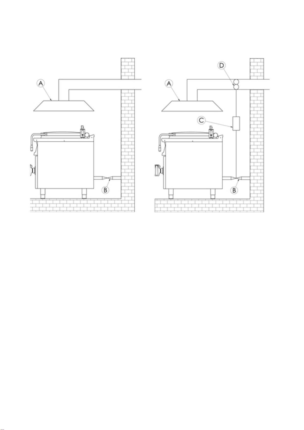
whois competent for this and according to the valid standards. The device can be instalated in good ventilated
room. When it is possible place the device under the fumehood to suck off the products of combustion. Air
needy to the burning is 2m/3/h/kW ot the performance of the instaled device. The device can be instalated
separately or in a set with devices of our production. Min. distance 10 cm from other subjects must be kept.It
is also necessary to prevent our product from contact with combustible materials. In this case you must make
corresponding changes to secure heat izolation of combustible parts (for example:place between the device
and combustible material azbestos plate).
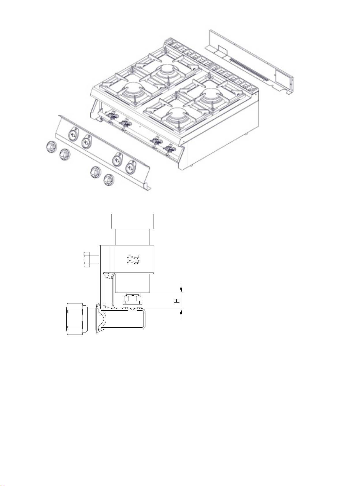
PIPE FOR GAS CONNECTION
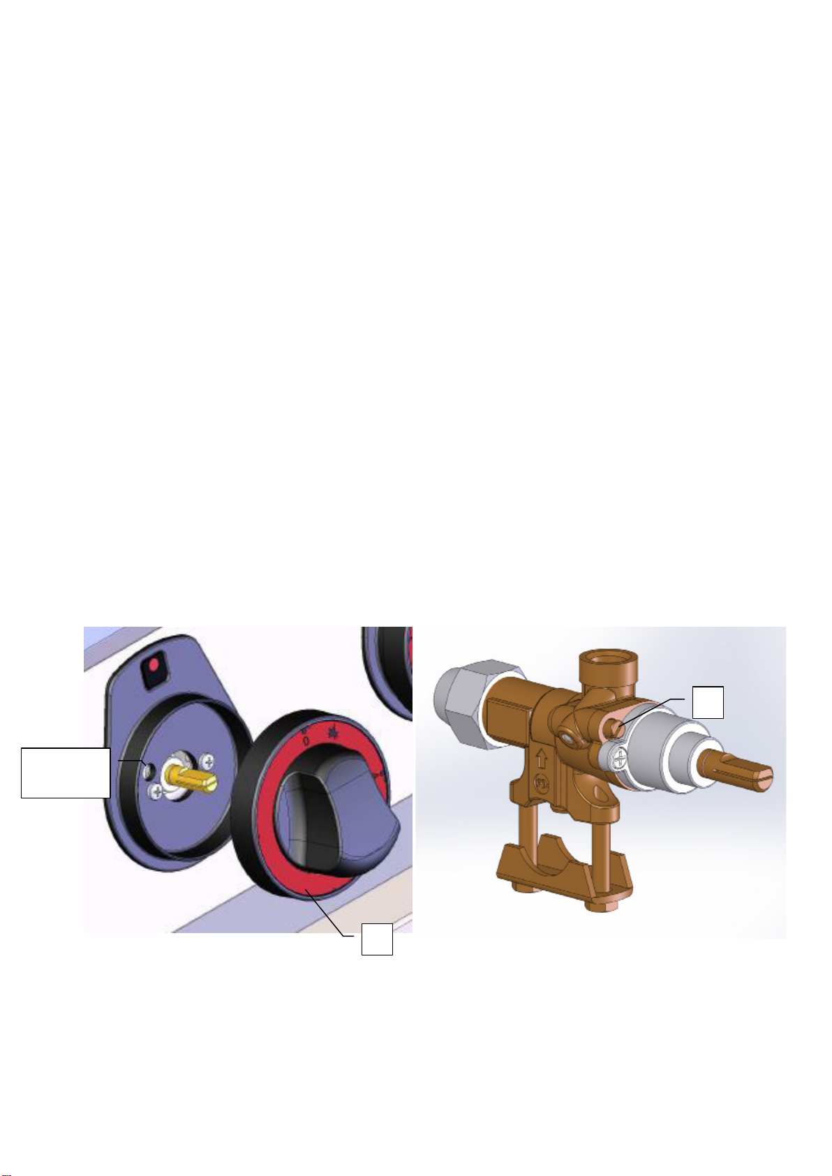
It must fi rst determine if the appliance is made for the same type of gas that will be used and thus conforms
to the indications on the label the type of gas to be used.
The conversion of gas pan to another type of gas you need to check if it corresponds to the type of gas
bearing, which is recommended in this guide.
Connecting the appliance to the gas distribution must be towable to a steel or copper tube complying with
applicable national requirements. This must be controlled on regular basis and changed if needed. Every
appliance must be equipped with shut-off valve and quick shut-off valve. Quick shut-off valve must be freely
accessible and within reach of the device. After installation, is necessary to check whether there is a gas leak.
To fi nd a gas leak you can use soapy water or spray for gas leak detection.
Do not use corrosive substances!! All our appliances are carefully controlled. Gas type, pressure and of the
categories listed named on the technical information plate.
Liquid gas connection:
Pressure for liquid gas connection must be 28 or 30 mbar for propane/butane and 37 mbar for propane. It
is necessary to check the technical label ,gauge the pressure and check the parameters of the nozzle is
installed with the required parameters of the nozzle according to the manufacturer‘s. If the pressure is lower
than 25mbar or higher than 37 mbar, THE APPLIANCE SHALL NOT TO BE CONNECTED.
Gas Connection:
Pressure for methane connection must be 18 or 20 mbar. It is necessary to check the technical label ,gauge
the pressure and check the parameters of the nozzle is installed with the required parameters of the nozzle
according to the manufacturer‘s. If the gas pressure is lower than 15mbar or higher than 22,5 mbar, THE
APPLIANCE SHALL NOT TO BE CONNECTED.
PIPE FOR GAS CONNECTION
It must fi rst determine if the appliance is made for the same type of gas that will be used and thus conforms
to the indications on the label the type of gas to be used.
The conversion of gas pan to another type of gas you need to check if it corresponds to the type of gas
bearing, which is recommended in this guide.
Connecting the appliance to the gas distribution must be towable to a steel or copper tube complying with
applicable national requirements. This must be controlled on regular basis and changed if needed. Every
appliance must be equipped with shut-off valve and quick shut-off valve. Quick shut-off valve must be freely
accessible and within reach of the device. After installation, is necessary to check whether there is a gas leak.
To fi nd a gas leak you can use soapy water or spray for gas leak detection.
Do not use corrosive substances!! All our appliances are carefully controlled. Gas type, pressure and of the
categories listed named on the technical information plate.
Liquid gas connection:
Pressure for liquid gas connection must be 28 or 30 mbar for propane/butane and 37 mbar for propane. It
is necessary to check the technical label ,gauge the pressure and check the parameters of the nozzle is
installed with the required parameters of the nozzle according to the manufacturer‘s. If the pressure is lower
than 25mbar or higher than 37 mbar, THE APPLIANCE SHALL NOT TO BE CONNECTED.
Gas Connection:
Pressure for methane connection must be 18 or 20 mbar. It is necessary to check the technical label ,gauge
the pressure and check the parameters of the nozzle is installed with the required parameters of the nozzle
according to the manufacturer‘s. If the gas pressure is lower than 15mbar or higher than 22,5 mbar, THE
APPLIANCE SHALL NOT TO BE CONNECTED.
6