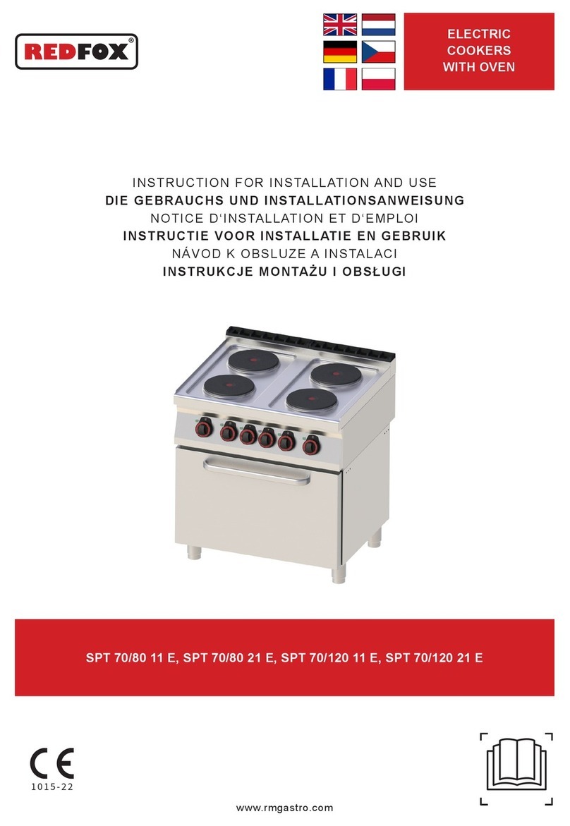
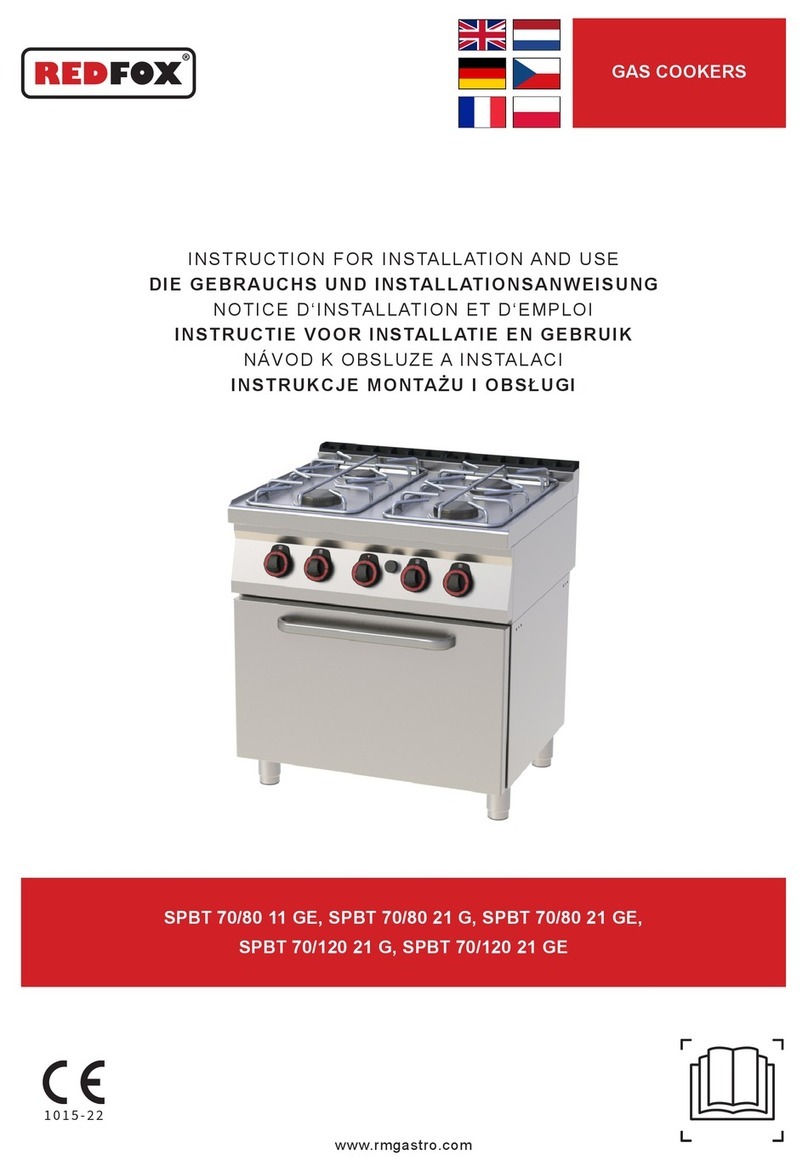
Redfox STP 70/08 G User manual

GAS COOKERS
1015-22
STP 70/08 G, STP 70/012 G, STP 70/80 G, STP 70/120 G, STPT 70/80 21 G,
STPT 70/80 21 GE, STPT 70/120 21 G, STPT 70/120 21 GE
www.rmgastro.com
INSTRUCTION FOR INSTALLATION AND USE
DIE GEBRAUCHS UND INSTALLATIONSANWEISUNG
NOTICE D‘INSTALLATION ET D‘EMPLOI
NÁVOD K OBSLUZE A INSTALACI

2023-03-13
CONTENT
Declaration of a standards conformity
Instruction for use
Cleaning and maintenance
3
16
18
INHALT
Die Normenübereinstimmungsdeklaration
Gebrauchsanweisung
Die Reinigung und instandshaltung
19
32
34
CONTENU
Déclaration de conformité
Mode d‘emploi
Nettoyage et entretien
35
48
50
OBSAH
Prohlášení o souladu s normami
Návod k použití
Čistění a údržba
57
71
74

DECLARATION OF A STANDARDS CONFORMITY
The producer confi rms that the devices agree with 2016/426/EU, 2014/35/EU, 2014/30/EU standards, rule
nr. 22/1997 sb., 258/2000 sb, 38/2001 sb, 118/2016 sb., 117/2016 sb. and with relevant goverment orders.
Instalation must be done with respect to valid standards. Attention, the producer refuses any responsibility
in case of direct or indirect damages which are caused due to wrong instalation, incorrect intervention or
modifi cation, insuffi cient maintenance, incorrect use and also possibly caused by other reasons presented by
items in sale conditions. This appliance is set only for skilled use and must be operated by qualifi ed persons
only. Parts set and secured by the producer or accredited person must not be rebuilt by user.
TECHNICAL DATA
Label with technical data is placed on the back side of the device. Study the electrical diagram of connection
and all following information before instalation.
MODEL Voltage
(V/HZ)
Total power
(kW)
Power E -
oven
(kW)
Power G
(kW)
Oven
(kW)
Dimension
(mm)
STP 70/08 G - 19,1 0 19,1 x 800x713x330
STP 70/80 G - 19,1 0 19,1 x 800x713x908
STP 70/012 G - 36,1 0 36,1 x 1200x713x330
STP 70/120 G - 36,1 0 36,1 x 1200x713x908
STPT 70/80 21 G - 25,4 0 25,4 6,3 (gas) 800x736x908
STPT 70/80 21 GE 400/3N/50 25,4 6,3 19,1 6,3 (electic) 800x736x908
STPT 70/120 21 G - 42,4 0 42,4 6,3 (gas) 1200x736x908
STPT 70/120 21 GE 400/3N/50 42,4 6,3 36,1 6,3 (electric) 1200x736x908
Recomended size of pots
4 kW - min. 14 cm; max. 38 cm
8,5 kW - min. 14 cm; max. 50 cm
Parts that have been set by the manufacturer or service technician during installation must not be
re-set by the operator.
Bod 123456
T (°C) 430 390 360 320 260 360
Temperature of the melt plate
3

Burner 8,5kW ; 404000161
nominal power input 8,5 kW ; reduced input power 2,5 kW
plyn tryska č.2 ø
[0,01mm]
kód spotřeba 1 hořák "nastavení prim.
vzduchu
litinový rošt (na obr
jako X) [mm]"
G30 30 mbar 145 404547084 0,27 kg/h open
G30 37 mbar 140 404547140 0,278 kg/h open
G30 50 mbar 130 404547083 0,266 kg/h open
G31 37 mbar 145 404547084 0,342 kg/h open
G20 20 mbar 215 404547097 0,928 m3/h 5
G20 25 mbar 205 404547096 0,924 m3/h 5
G25 20 mbar 240 404547240 1,034 m3/h 5
G25 25 mbar 215 404547097 1,006 m3/h 5
G25.1 25 mbar 235 404547254 1,002 m3/h 5
G27 20 mbar 250 404547102 1,119 m3/h 5
PILOT 0,23kW ; 404000310
plyn tryska č.10
ø [0,01mm]
kód spotřeba
G30 30 mbar 24 404547024 0,0149 kg/h
G30 37 mbar 24 404547024 0,0168 kg/h
G30 50 mbar 24 404547024 0,0166 kg/h
G31 37 mbar 24 404547024 0,016 kg/h
G20 20 mbar 24 404547024 0,023 m3/h
G20 25 mbar 24 404547024 0,024 m3/h
G25 20 mbar 24 404547024 0,027 m3/h
G25 25 mbar 24 404547024 0,028 m3/h
G25.1 25 mbar 24 404547024 0,029 m3/h
G27 20 mbar 24 404547024 0,03 m3/h
Nozzle table
4

HOŘÁK 4kW ; 404000160
nominal power input 4 kW ; reduced input power 2,5 kW
plyn tryska č.2 ø
[0,01mm]
kód spotřeba 1 hořák "nastavení prim.
Vzduchu
litinový rošt (na obr
označeno jako H)
[mm]"
G30 30 mbar 100 404547101 0,128 kg/h open
G30 37 mbar 95 404547078 0,125 kg/h open
G30 50 mbar 90 404547090 0,13 kg/h open
G31 37 mbar 100 404547101 0,163 kg/h open
G20 20 mbar 145 404547084 0,437 m3/h close
G20 25 mbar 135 404557135 0,417 m3/h close
G25 20 mbar 165 404547088 0,494 m3/h close
G25 25 mbar 145 404547084 0,417 m3/h close
G25.1 25 mbar 150 404547152 0,489 m3/h close
G27 20 mbar 165 404547088 0,491 m3/h close
Nozzle table
PILOT 0,23kW ; 404000310
plyn tryska č.10
ø [0,01mm]
kód spotřeba
G30 30 mbar 24 404547024 0,0149 kg/h
G30 37 mbar 24 404547024 0,0168 kg/h
G30 50 mbar 24 404547024 0,0166 kg/h
G31 37 mbar 24 404547024 0,016 kg/h
G20 20 mbar 24 404547024 0,023 m3/h
G20 25 mbar 24 404547024 0,024 m3/h
G25 20 mbar 24 404547024 0,027 m3/h
G25 25 mbar 24 404547024 0,028 m3/h
G25.1 25 mbar 24 404547024 0,029 m3/h
G27 20 mbar 24 404547024 0,03 m3/h
5

Nozzle table
HOŘÁK 6,6 kW ; 404000172
nominal power input 6,6 kW ; reduced input power 2,5 kW
plyn tryska č.11
ø [0,01mm]
kód spotřeba 1 hořák
G30 30 mbar 125 404000256 0,214 kg/h
G30 37 mbar 120 404547197 0,216 kg/h
G30 50 mbar 110 404000240 0,218 kg/h
G31 37 mbar 125 404000256 0,272 kg/h
G20 20 mbar 190 404000237 0,715 m3/h
G20 25 mbar 175 404000198 0,703 m3/h
G25 20 mbar 210 404000258 0,83 m3/h
G25 25 mbar 190 404000237 0,788 m3/h
G25.1 25 mbar 200 404000199 0,821 m3/h
G27 20 mbar 210 404000258 0,831 m3/h
PILOT 0,13kW
plyn tryska č.10
ø [0,01mm]
kód spotřeba
G30 30 mbar 19 404000241 0,004 kg/h
G30 37 mbar 19 404000241 0,004 kg/h
G30 50 mbar 19 404000241 0,004 kg/h
G31 37 mbar 19 404000241 0,004 kg/h
G20 20 mbar 27 404547031 0,13 m3/h
G20 25 mbar 27 404547031 0,014 m3/h
G25 20 mbar 27 404547031 0,014 m3/h
G25 25 mbar 27 404547031 0,014 m3/h
G25.1 25 mbar 27 404547031 0,014 m3/h
G27 20 mbar 27 404547031 0,016 m3/h
Oven burner 6kW - 404000169
plyn tryska č.2 ø
[0,01mm]
kód spotřeba nastavení prim.
Vzduchu(H)
G30 30 mbar 125 404547082 0,4487 kg/h 40,30
G30 37 mbar 120 404457121 0,4784 kg/h 40,30
G30 50 mbar 110 404547108 0,4789 kg/h 41,30
G31 37 mbar 120 404457121 0,469 kg/h 32,5
G20 20 mbar 180 404547092 0,618 m3/h 20
G20 25 mbar 175 404547089 0,652 m3/h 20
G25 25 mbar 195 404547195 0,719 m3/h 20
G25.1 25 mbar 260 404547103 0,704 m3/h 20
G27 20 mbar 205 404547096 0,737 m3/h 20
G27 20 mbar 27 404547031 0,016 m3/h - -
6

Oven pilot - 404000003 - 0,23 kW
plyn tryska č.10
ø [0,01mm]
kód spotřeba nastavení prim.
vzduchu
G30 30 mbar 19 404000241 0,0123 kg/h
G30 37 mbar 19 404000241 0,0146 kg/h
G30 50 mbar 19 404000241 0,0167 kg/h
G31 37 mbar 19 404000241 0,0157 kg/h
G20 20 mbar 36 404000221 0,024 m3/h
G20 25 mbar 36 404000221 0,021 m3/h
G25 25 mbar 36 404000221 0,025 m3/h
G25.1 25 mbar 36 404000221 0,024 m3/h
G27 20 mbar 36 404000221 0,024 m3/h
G27 20 mbar 27 404547031 0,016 m3/h - -
Nozzle table
The maximum and reduced rated heat input in kW is related to the Hi of the gas used.
If the product is connected to LPG, the gas cylinder must be in a suiciently ventilated room.
AL,AT,BG,CY,HR,DK,EE,FI,GR,LV
LT,MK,NO,RO,SK,SI,SE,CH,TR
Cat.
Cat.
Cat.
Cat.
Pn
Cat.
Pn
Pn
Pn
Pn
II2H3B/P
II2H3+
20, 30, 50
20, 28-30/37
LU
I2E
20
AL,CY,GR,IE,IT,LT,MK,PT,GB,CZ,SK
SI,ES,CH,TR
NL, RO
II2L3B/P
25,30
BE, FR
II2E+3+
20/25, 28-30/37
DE
II2ELL3B/P
20,50
I3B/P
30
RO
II2E3B/P
20,30
HU
II2HS3B/P
30,25
PL
II2ELwLs3B/P
20,13,37
IS, MT
Table of gases for which the product is intended
7

PACKING AND DEVICE CHECK
The device leaves our stocks properly packed with appropriate symbols and labels. There are also appropriate
instructions for use. In case the packing shows bad handling or damage, it must be reclaimed at transporter
immediately by writing and signing of a damage protocol.
Important notice:
-This product is only intended for use inside.
Never use the appliance if it has a damaged supply cable or plug, if it is not working correctly, has fallen to
the ground and been damaged or fallen into water. In such cases take the appliance to a professional service
in order to verify that it is safe and works correctly.
• only for proffesional use
• this instructing guide must be read properly and carefully because it contains important information about
safety elements, installation, use
• these recommendations refer to this product
• this product corresponds with valid standards
• this guide must be properly deposited for future use
• keep the children away from manipulation with the product
• when selling or moving the product to another place it is necessary top make yourself sure that the staff
or the professional service has got acquainted with control and installation instructions from enclosed guide
• only authorised person can operate the product
• it can not be switched on without supervision
• we recommend to have the product checked by professional service min. once a year
• only original spare parts can be used for repairs
• the product can not be cleaned by the water jet or pressure shower
• by damage or break down disconnect all the feeders (water, gas, electricity) and call professional service
• producer refuses any responsibility in case of damages caused by wrong installation, by disobserving of
above mentioned recommendations or by other use etc.
8

TECHNICAL INSTRUCTIONS FOR INSTALATION AND REGULATION
Important:
The manufacturer does not provide warranty for defects caused by improper use, failure to instructions
contained in the attached instructions for use and mistreatment of the appliances.
Installation, adjustment and repair of appliances for kitchens, as well as their removal because of possible
damage to the gas can be carried out only under a maintenance contract, this contract may be signed with an
authorized dealer, and must be complied with regulations and technical standards and regulations regarding
the installation, power supply, gas connection and health & safety system.
These instructions are intended for the qualifi ed technician who must perform the installation, put it into
operation and test the appliance.
Any activity as settings, placement, rebalancing etc, must be made only when is device disconnected from
electricity. If it is necessary to have the device connected to the electricity you must keep the highest attention
to avoid any injuries.
DEVICE INSTALATION
Instalation, setting, rebuilding for another gas type, putting into operation must be done by qualifi ed person
whois competent for this and according to the valid standards. The device can be instalated in good ventilated
room. When it is possible place the device under the fumehood to suck off the products of combustion. Air
needy to the burning is 2m/3/h/kW ot the performance of the instaled device. The device can be instalated
separately or in a set with devices of our production. Min. distance 10 cm from other subjects must be kept.It
is also necessary to prevent our product from contact with combustible materials. In this case you must make
corresponding changes to secure heat izolation of combustible parts (for example:place between the device
and combustible material azbestos plate).
Data Type of gas
Burner 8,5 kW G30
28-30 mbar
G30
37 mbar
G30
50 mbar
G20
20 mbar
G25
25 mbar
G25
20 mbar
G20
25 mbar
Main burner diameter
1/100mm 145 140 130 215 225 245 205
Air kontrol _settings (mm) open open open 3,5 3,5 3,5 3,5
Gas Consumption 0,670 kg/h 0,670 kg/h 0,670 kg/h 0,899 m3/h 1,046 m3/h 1,046 m3/h 0,899 m3/h
Burner 4 kW
Main burner diameter
1/100mm 95 90 85 150 155 165 140
Air kontrol _settings (mm) open open open closed closed closed closed
Gas Consumption 0,355 kg/h 0,355 kg/h 0,355 kg/h 0,476 m3/h 0,554 m3/h 0,554 m3/h 0,476 m3/h
Pilot burner
diameter 1/100mm 24 24 24 adjusted adjusted adjusted adjusted
Data Type of gas
Burner 8,5 kW G25.1
25 mbar
G2.350
13 mbar
G27
20 mbar
G31
30-37 mbar
G31
37 mbar
G31
50 mbar
Main burner diameter
1/100mm 240 315 250 145 140 130
Air kontrol _settings (mm) 3,5 open 3,5 open open open
Gas Consumption 1,044 m3/h 1,249 m3/h 1,097 m3/h 0,660 kg/h 0,660 kg/h 0,660 kg/h
Burner 4 kW
Main burner diameter
1/100mm 160 205 170 95 90 85
Air kontrol _settings (mm) closed closed closed open open open
Gas Consumption 0,553 m3/h 0,661 m3/h 0,581 m3/h 0,350 kg/h 0,350 kg/h 0,350 kg/h
Pilot burner
diameter 1/100mm adjusted adjusted adjusted 24 24 24
PIPE FOR GAS CONNECTION
It must fi rst determine if the appliance is made for the same type of gas that will be used and thus conforms
to the indications on the label the type of gas to be used.
The conversion of gas pan to another type of gas you need to check if it corresponds to the type of gas
bearing, which is recommended in this guide.
Connecting the appliance to the gas distribution must be towable to a steel or copper tube complying with
applicable national requirements. This must be controlled on regular basis and changed if needed. Every
appliance must be equipped with shut-off valve and quick shut-off valve. Quick shut-off valve must be freely
accessible and within reach of the device. After installation, is necessary to check whether there is a gas leak.
To fi nd a gas leak you can use soapy water or spray for gas leak detection.
Do not use corrosive substances!! All our appliances are carefully controlled. Gas type, pressure and of the
categories listed named on the technical information plate.
Liquid gas connection:
Pressure for liquid gas connection must be 28 or 30 mbar for propane/butane and 37 mbar for propane. It
is necessary to check the technical label ,gauge the pressure and check the parameters of the nozzle is
installed with the required parameters of the nozzle according to the manufacturer‘s. If the pressure is lower
than 25mbar or higher than 37 mbar, THE APPLIANCE SHALL NOT TO BE CONNECTED.
Gas Connection:
Pressure for methane connection must be 18 or 20 mbar. It is necessary to check the technical label ,gauge
the pressure and check the parameters of the nozzle is installed with the required parameters of the nozzle
according to the manufacturer‘s. If the gas pressure is lower than 15mbar or higher than 22,5 mbar, THE
APPLIANCE SHALL NOT TO BE CONNECTED.
PACKING AND DEVICE CHECK
The device leaves our stocks properly packed with appropriate symbols and labels. There are also appropriate
instructions for use. In case the packing shows bad handling or damage, it must be reclaimed at transporter
immediately by writing and signing of a damage protocol.
Important notice:
-This product is only intended for use inside.
Never use the appliance if it has a damaged supply cable or plug, if it is not working correctly, has fallen to
the ground and been damaged or fallen into water. In such cases take the appliance to a professional service
in order to verify that it is safe and works correctly.
• only for proffesional use
• this instructing guide must be read properly and carefully because it contains important information about
safety elements, installation, use
• these recommendations refer to this product
• this product corresponds with valid standards
• this guide must be properly deposited for future use
• keep the children away from manipulation with the product
• when selling or moving the product to another place it is necessary top make yourself sure that the staff
or the professional service has got acquainted with control and installation instructions from enclosed guide
• only authorised person can operate the product
• it can not be switched on without supervision
• we recommend to have the product checked by professional service min. once a year
• only original spare parts can be used for repairs
• the product can not be cleaned by the water jet or pressure shower
• by damage or break down disconnect all the feeders (water, gas, electricity) and call professional service
• producer refuses any responsibility in case of damages caused by wrong installation, by disobserving of
above mentioned recommendations or by other use etc.
9
SAFETY MEASURES FROM THE STANDPOINT OF THE FIRE
PROTECTION ACCORDING TO EN 061008 ČL. 21
• only adults can operate the device
• device must be safely used in common surroundings according to EN 332000-4-462; EN 332000-4-42. You
must switch the gas device off under the circumstances leading: to the danger of the temporary rise of the
combustion gas or steam or during works when there is a big possibilityof rise ot the temporary fi re danger
or explosion (for example: to stick linoleum, PVC etc.).
• before you start to instal the device you must get the licence for connection to the gas feeder from the
gasworks
• device must be placed so as to stand or hang on the noncombustible surface which is on each side 10
cm larger than the device. No subjects from combustible materials can be placed directly on the device
or in distance which is shorter than safety distance (the shortestdistance is 50 cm in the direction of the
heat emission and 10 cm in other directions).- safety distances from various materials of different degree of
combustion and information about the degree of comb. of common building materials - see chart:
Chart:
Combustion degree of building materials classifi ed according to the combustion degree of materials and
products (EN 730823)
A noncombustible granit, sandstone, concretes,bricks, ceramic wallfacing tiles, plaster
B uneasily combustible akumine, heraklite, lihnos, itavere
C1 hardly combustible leafy wood, plywood, sirkoklit, rare paper formica
C2 middle combustible fi breboards, solodure, cork boards, rubber,fl oor-coverings
C3 easily combustible wood-fi breboards, polystyrene,polyurethane, PVC
Devices must be instalated in a safe way. When instaling you must respect corresponding project, safety and
hygienic orders according to:
• EN 061008 fi re protection of local devices and sources of heat
• EN 332000 (33 2000-4-482; 33 2000-4-42) surrounding for electric devices ČSN EN 1775 Gas supplying
• Gas fi ttings in the buildings - the highest operational pressure < 5 bar - operation demands
• § 10 law nr. 185/2001 Sb. about waste
10

Outlet hood with natural extraction (A). Flue gas provides a natural chimney draft.
Outlet hood without natural extraction. Flue gas is secured by a fan (D) (forced extraction). In this
case, it is necessary to secure the connection with a gas feeder (B) to turn off the gas supply in case
of failure.
NATURAL EXTRACTION FORCED EXTRACTION
CHIMNEY DESIGN FOR AN APPLIANCE –TYPE A
SAFETY MEASURES FROM THE STANDPOINT OF THE FIRE
PROTECTION ACCORDING TO EN 061008 ČL. 21
• only adults can operate the device
• device must be safely used in common surroundings according to EN 332000-4-462; EN 332000-4-42. You
must switch the gas device off under the circumstances leading: to the danger of the temporary rise of the
combustion gas or steam or during works when there is a big possibilityof rise ot the temporary fi re danger
or explosion (for example: to stick linoleum, PVC etc.).
• before you start to instal the device you must get the licence for connection to the gas feeder from the
gasworks
• device must be placed so as to stand or hang on the noncombustible surface which is on each side 10
cm larger than the device. No subjects from combustible materials can be placed directly on the device
or in distance which is shorter than safety distance (the shortestdistance is 50 cm in the direction of the
heat emission and 10 cm in other directions).- safety distances from various materials of different degree of
combustion and information about the degree of comb. of common building materials - see chart:
Chart:
Combustion degree of building materials classifi ed according to the combustion degree of materials and
products (EN 730823)
A noncombustible granit, sandstone, concretes,bricks, ceramic wallfacing tiles, plaster
B uneasily combustible akumine, heraklite, lihnos, itavere
C1 hardly combustible leafy wood, plywood, sirkoklit, rare paper formica
C2 middle combustible fi breboards, solodure, cork boards, rubber,fl oor-coverings
C3 easily combustible wood-fi breboards, polystyrene,polyurethane, PVC
Devices must be instalated in a safe way. When instaling you must respect corresponding project, safety and
hygienic orders according to:
• EN 061008 fi re protection of local devices and sources of heat
• EN 332000 (33 2000-4-482; 33 2000-4-42) surrounding for electric devices ČSN EN 1775 Gas supplying
• Gas fi ttings in the buildings - the highest operational pressure < 5 bar - operation demands
• § 10 law nr. 185/2001 Sb. about waste
11

CHECK THE GAS TYPE THE DEVICE IS ADJUSTED FOR
Our appliances are certifi ed and regulated the natural gas (see technical plate). Conversion or adaptation to
a different type of gas must be performed by authorized personnel. Nozzles for different types of gas are in a
bag provided with the gas cooker and are marked in hundredths of mm (table of technical data pipes).
Nozzle replacement and pressure adjustment (Fig. 1, 2, 3)
It should proceed as follows:
Remove grid from top part of cooker, whole top part of the burner and GN (note 1, 2, 3, 4, fi g. 1)
Unscrew nozzle (note 5, fi g. 2, 3) with wrench and replace it for another by the desired type of gas.
Perform the assembly in reverse order. Make sure that different parts fi t closely to each other. Air control (fi g.
3, note 8) is always fully open.
Pilot burner can be adjust so, that is need untie safety nut (note 6, fi g. 3) with wrench. Then with wrench
number, tie or untie nozzle (note 7, fi g. 3) and adjust the fl ame into desired size.
Important:
After what was done adjusting the appliance to another type of gas, it is necessary to change the gas
indicated on the technical plate located in a visible location on the back of the device.
Adjusting fl ame at reduced performance „SAVING“
Flame at reduced performance „SAVING“, can be set with screw placed in the valve body (note. 1, fi g. 5)
positioned next to valve shaft
For adjusting proceed as follows:
- Remove the control knob (note. 1, fi g. 4) pulling towards you
- Adjust the fl ame through hole with fl at screwdriver
Otvor pro
seřízení
1
1
4 5
HOLE FOR FLAME
ADJUSTING
12

13

CHECK THE GAS TYPE THE DEVICE IS ADJUSTED FOR
Our appliances are certifi ed and regulated the natural gas (see technical plate). Conversion or adaptation to
a different type of gas must be performed by authorized personnel. Nozzles for different types of gas are in a
bag provided with the gas cooker and are marked in hundredths of mm (table of technical data pipes).
Nozzle replacement and pressure adjustment (Fig. 1, 2, 3)
It should proceed as follows:
Remove grid from top part of cooker, whole top part of the burner and GN (note 1, 2, 3, 4, fi g. 1)
Unscrew nozzle (note 5, fi g. 2, 3) with wrench and replace it for another by the desired type of gas.
Perform the assembly in reverse order. Make sure that different parts fi t closely to each other. Air control (fi g.
3, note 8) is always fully open.
Pilot burner can be adjust so, that is need untie safety nut (note 6, fi g. 3) with wrench. Then with wrench, tie
or untie nozzle (note 7, fi g. 3) and adjust the fl ame into desired size.
Important:
After what was done adjusting the appliance to another type of gas, it is necessary to change the gas
indicated on the technical plate located in a visible location on the back of the device.
Adjusting fl ame at reduced performance „SAVING“
Flame at reduced performance „SAVING“, can be set with screw placed in the valve body (note. 1, fi g. 5)
positioned next to valve shaft
For adjusting proceed as follows:
- Remove the control knob (note. 1, fi g. 4) pulling towards you
- Adjust the fl ame through hole with fl at screwdriver
3
6
4
5
3) Nozzle of main burner
4) Unscrew nut
5) Unmount gas supply copper
pipe from pilot nozzle.
6) Replace pilot nozzle for another
by the desired diameter
14

CHECK THE GAS TYPE THE DEVICE IS ADJUSTED FOR (oven)
Our appliances are certifi ed and regulated the natural gas (see technical plate). Conversion or
adaptation to a different type of gas must be performed by authorized personnel. Nozzles for diffe-
rent types of gas are in a bag provided with the gas cooker and are marked in hundredths of mm
(table of technical data pipes).
Instructions:
Main burner
1) Open the oven door and take out the cover sheet. (false bottom of oven).
2) Dismount the cover of main burner (fi g. 2)
3) According to picture (fi g. 3) unscrew the nozzle from the main burner and replace with nozzles
according to table „TECHNICAL DATA“
4) Adjust the air intake for the relevant gas according to table „TECHNICAL DATA“
Pilot burner
1) Unscrew the nut according to pic. 5, pos. 1
2) Disassemble the copper supply pipe from the pilot burner.
3) unscrew the nozzle from the main burner according to pic. 5, pos. 2 and replace with nozzles
according to the “BURNER TECHNICAL DATA” table.
4) Reinstall the copper pipe to the pilot burner and attach using the nut according to pic. 5, pos. 1.
1
3
2
4
5
pos. 1
pos. 2
NOZZLE
15

INSTRUCTIONS FOR USE
gnition of the burner and regulation of the performance
Turn the regulation knob of the competent burner (1) into position „ignition of the main burner“ and then
press it down and hold it. Ignite the burner with piezzo lighter (2). After ignition of the burner hold the knob (1)
pressed several seconds till the thermofuse gets hot. Then release the button. If the fl ame goes out repeat
the whole process once more.
Lower performance sporo:
By turning the knob (A) into position „sporo“ you set the burning of the burner for sporo (lower performance)
How to switch the burner off:
Turn the knob (A) into position“0“.
1
BURNER KONTROL KNOB
PIEZZO LIGHTER
1
Switched off
ignition of the main burner
Full power
Lowered power
1
2
2
The possibility of a visual inspection of the pilot burner fl ame, remove the center plate by hook which are
included.
INSTRUCTIONS FOR USE
gnition of the burner and regulation of the performance
Turn the regulation knob of the competent burner (A) into position „ignition of the main burner“ and then press
it down and hold it. Ignite the burner with lighter or matches. After ignition of the burner hold the knob (A)
pressed several seconds till the thermofuse gets hot. Then release the button. If the fl ame goes out repeat
the whole process once more.
Lower performance sporo:
By turning the knob (A) into position „sporo“ you set the burning of the burner for sporo (lower performance)
How to switch the burner off:
Turn the knob (A) into position“0“.
1
BURNER KONTROL KNOB
1
Switched off
ignition of the main burner
Full power
Lowered power
16

INSTRUCTIONS FOR USE
gnition of the burner and regulation of the performance
Turn the regulation knob of the competent burner (1) into position „ignition of the main burner“ and then
press it down and hold it. Ignite the burner with piezzo lighter (2). After ignition of the burner hold the knob (1)
pressed several seconds till the thermofuse gets hot. Then release the button. If the fl ame goes out repeat
the whole process once more.
Lower performance sporo:
By turning the knob (A) into position „sporo“ you set the burning of the burner for sporo (lower performance)
How to switch the burner off:
Turn the knob (A) into position“0“.
1
BURNER KONTROL KNOB
PIEZZO LIGHTER
1
Switched off
ignition of the main burner
Full power
Lowered power
1
2
2
The possibility of a visual inspection of the pilot burner fl ame, remove the center plate by hook which are
included.
e hotplate is used for cooking with pots, which are moved on its surface. e hotplate is not used, for
example, for frying eggs, grilling meat, frying pancakes, etc.
CAUTION - e hotplate is extremely hot when heated and operated.
17

CLEANING AND MAINTENANCE
It is recommended to have the device checked by the professional service min. once a year. All interventions
must be done by qualifi ed person who is competent for this.
ATTENTION!
The device cannot be cleaned by direct or pressure water. Clean it daily. Daily maintenance keeps longer
useful life and effi ciency of the device. Before cleaning make sure to have disconnected the device from
electricity. Always switch off the main feeder to the device. Stain-less parts wash with moist cleaning cloth
and detergent without groove parts than wash it with clean water and dry it by the cloth. Do not use abrasive
and corrosive detergents.
WHAT TO DO IN CASE OF BREAK-DOWN
Switch off the electric feeder and call seller´s proffesional service.
INDICATION:
Guarentee does not cover all consumption parts succumable to common wear (rubber seals, bulbs, glas and
plastic parts etc.). The guarantee does not refer to the devices which were not instaled in correspondance with
instructions - by qualifi ed worker, in confi rmity with standards and when somebody handled incompetently the
device (interventions into inner equipment) or the device was operated by nonqualifi ed staff or at variance
with instructions for use. Guarantee does not also cover the damages caused due to infl uance of nature or
other outer intervention.
Point for cleaning steel-alloy plate:
• Heat up the device
• Turn of the device
• The plate pull off with scraper
• Apply water to chemistry (RM gril) and clean the plate from residual dirt and sediment
• Apply pure water (The solution is with vinegar or lemon)
• Pull off the water and than to dry the plate with rag
• Turn on the device up to 70 °C and from the plate let evaporate residual humidity
• To smear the grill areas with vegetable oil
Point for cleaning chrome plate:
• Heat up the device
• Turn of the device
• The plate pull off with plastic scraper
• Apply water with a saponate and clean the plate with a sponge
• Apply pure water
• Pull off the water and than to dry the plate with rag
• Turn on the device up to 70 °C and from the plate let evaporate residual humidity
18

DIE NORMENÜBEREINSTIMMUNGSDEKLARATION
Der Produzent erklärt, daß die Geräte in einer Übereinstimmung mit den Vorschriften der
2016/426/EU, 2014/35/EU, 2014/30/EU dem Gesetz Nr. 22/1997 sb., nr. 258/2000 sb., nr. 38/2001 sb. der
Sammlung und zugehörigen Regierungsverordnungen stehen. Die Installation muss mit der Absicht auf
geltende Normen durchgeführt werden. Vorsicht, im Falle einer direkten oder indirekten Beschädigung,
die sich auf falsche Installation, unrichtigen Eingriff oder Anpassungen, ungenügende Instandshaltung,
unrichtige Verwendung beziehen, und welche eventuell durch andere Ursachen, als in Punkten der
Verkaufsbedingungen angeführt ist, so verzichtet der Importeur auf jegliche Verantwortung. Dieses Gerät ist
nur für fachliche Verwendung bestimmt und muß durch qualifi zierte Person bedient werden. Teile, die nach
der Einstellung durch den Hersteller oder durch befugte Person gesichert wurden, dürfen vom Benutzer
keineswegs umgestellt werden.
DIE TECHNISCHEN DATEN
Das Schild mit technischen Angaben ist auf der Rückseite des Gerätes angebracht. Studieren sie vor der
Installation das elektrische Schema der Einschließung und alle folgende Informationen durch.
MODEL Spannung
(V/HZ)
Leistungsauf-
nahme
insgesamt
(kW)
Leistungsauf-
nahme E -
Backofen
(kW)
Leistungsaufna-
hme G
(kW)
Backofen
(kW)
Abmessungen
(mm)
STP 70/08 G - 19,1 0 19,1 x 800x713x330
STP 70/80 G - 19,1 0 19,1 x 800x713x908
STP 70/012 G - 36,1 0 36,1 x 1200x713x330
STP 70/120 G - 36,1 0 36,1 x 1200x713x908
STPT 70/80 21 G - 25,4 0 25,4 6,3 (plynová) 800x736x908
STPT 70/80 21 GE 400/3N/50 25,4 6,3 19,1 6,3 (elektrická) 800x736x908
STPT 70/120 21 G - 42,4 0 42,4 6,3 (plynová) 1200x736x908
STPT 70/120 21 GE 400/3N/50 42,4 6,3 36,1 6,3 (elektrická) 1200x736x908
Topfdurchmesser
4 kW - min. 14 cm; max. 38 cm
8,5 kW - min. 14 cm; max. 50 cm
Teile, die vom Hersteller oder Servicetechniker bei der Installation eingestellt wurden, dürfen vom
Bediener nicht neu eingestellt werden.
Bod 123456
T (°C) 430 390 360 320 260 360
Temperatur der Schmelzplatte
19

Düsentisch
Brenner 8,5kW ; 404000161
Nennleistung 8,5 kW ; reduzierte Leistung 2,5 kW
plyn tryska č.2 ø
[0,01mm]
kód spotřeba 1 hořák "nastavení prim.
vzduchu
litinový rošt (na obr
jako X) [mm]"
G30 30 mbar 145 404547084 0,27 kg/h open
G30 37 mbar 140 404547140 0,278 kg/h open
G30 50 mbar 130 404547083 0,266 kg/h open
G31 37 mbar 145 404547084 0,342 kg/h open
G20 20 mbar 215 404547097 0,928 m3/h 5
G20 25 mbar 205 404547096 0,924 m3/h 5
G25 20 mbar 240 404547240 1,034 m3/h 5
G25 25 mbar 215 404547097 1,006 m3/h 5
G25.1 25 mbar 235 404547254 1,002 m3/h 5
G27 20 mbar 250 404547102 1,119 m3/h 5
PILOT 0,23kW ; 404000310
plyn tryska č.10
ø [0,01mm]
kód spotřeba
G30 30 mbar 24 404547024 0,0149 kg/h
G30 37 mbar 24 404547024 0,0168 kg/h
G30 50 mbar 24 404547024 0,0166 kg/h
G31 37 mbar 24 404547024 0,016 kg/h
G20 20 mbar 24 404547024 0,023 m3/h
G20 25 mbar 24 404547024 0,024 m3/h
G25 20 mbar 24 404547024 0,027 m3/h
G25 25 mbar 24 404547024 0,028 m3/h
G25.1 25 mbar 24 404547024 0,029 m3/h
G27 20 mbar 24 404547024 0,03 m3/h
20
This manual suits for next models
7
Table of contents
Languages:
Other Redfox Cooker manuals

Redfox
Redfox SPT 70/80 11 GE User manual

Redfox
Redfox SPT 90/80-11 GE User manual

Redfox
Redfox SPBT 70/80 11 GE User manual

Redfox
Redfox SP 70/04 E User manual

Redfox
Redfox SPB 70/04 G Quick start guide

Redfox
Redfox SPT 70/80 11 E User manual

Redfox
Redfox SP 70/04 G User manual

Redfox
Redfox SPL 70/04 E User manual
Popular Cooker manuals by other brands

Zanussi
Zanussi ZCG63260XE user manual

Cook's Companion
Cook's Companion CCPC46L Instruction manual & recipes

Zanussi
Zanussi ZCG 7701X Instruction booklet

Parkinson Cowan
Parkinson Cowan Country Cottage 55 Operating and installation instructions

Zanussi Electrolux
Zanussi Electrolux U30356 ZKC6010 user manual

Creda
Creda HB49127 Instruction and recipe book