10
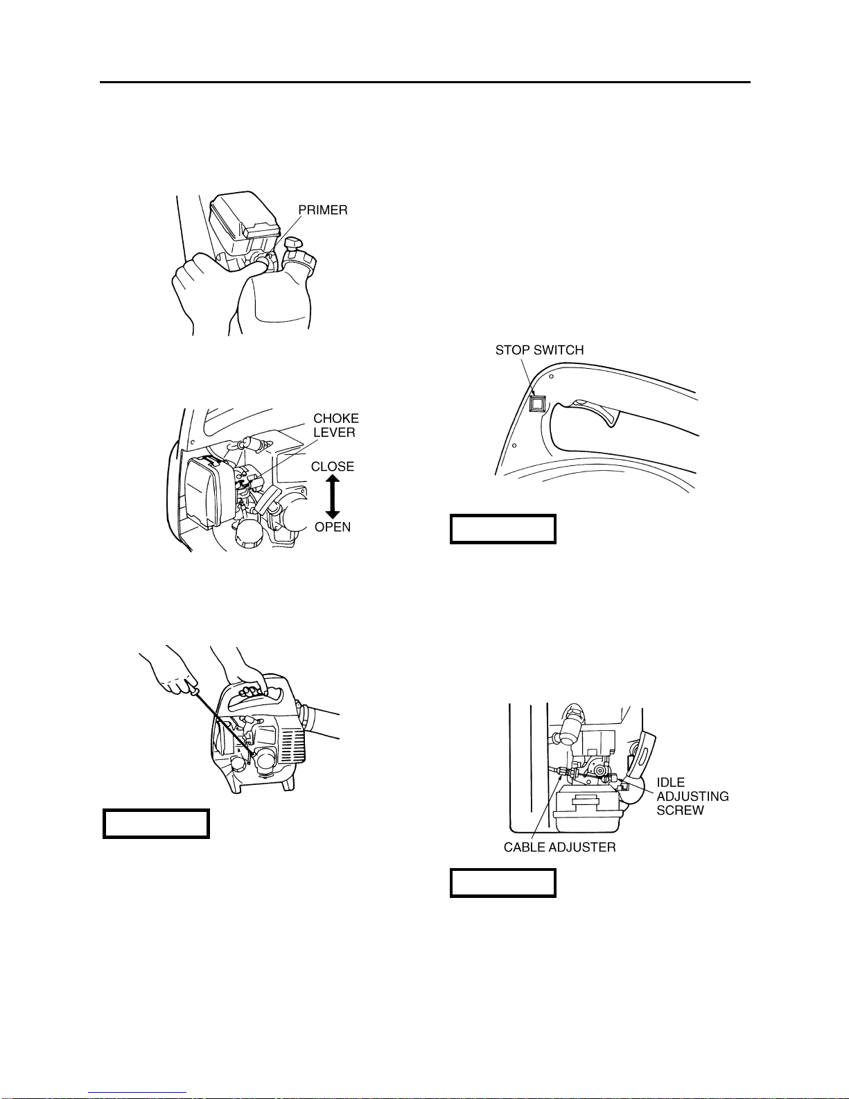
■FUEL FILTER
•A clogged fuel filter may cause poor
acceleration of the engine. Check
periodically to see if the filter is clogged
with dirt. The filter can be taken out of the
fueling port using a small wire hook.
Disconnect the filter assembly from the fuel
pipe and unhook the retainer to
disassemble it. Clean the components with
gasoline.
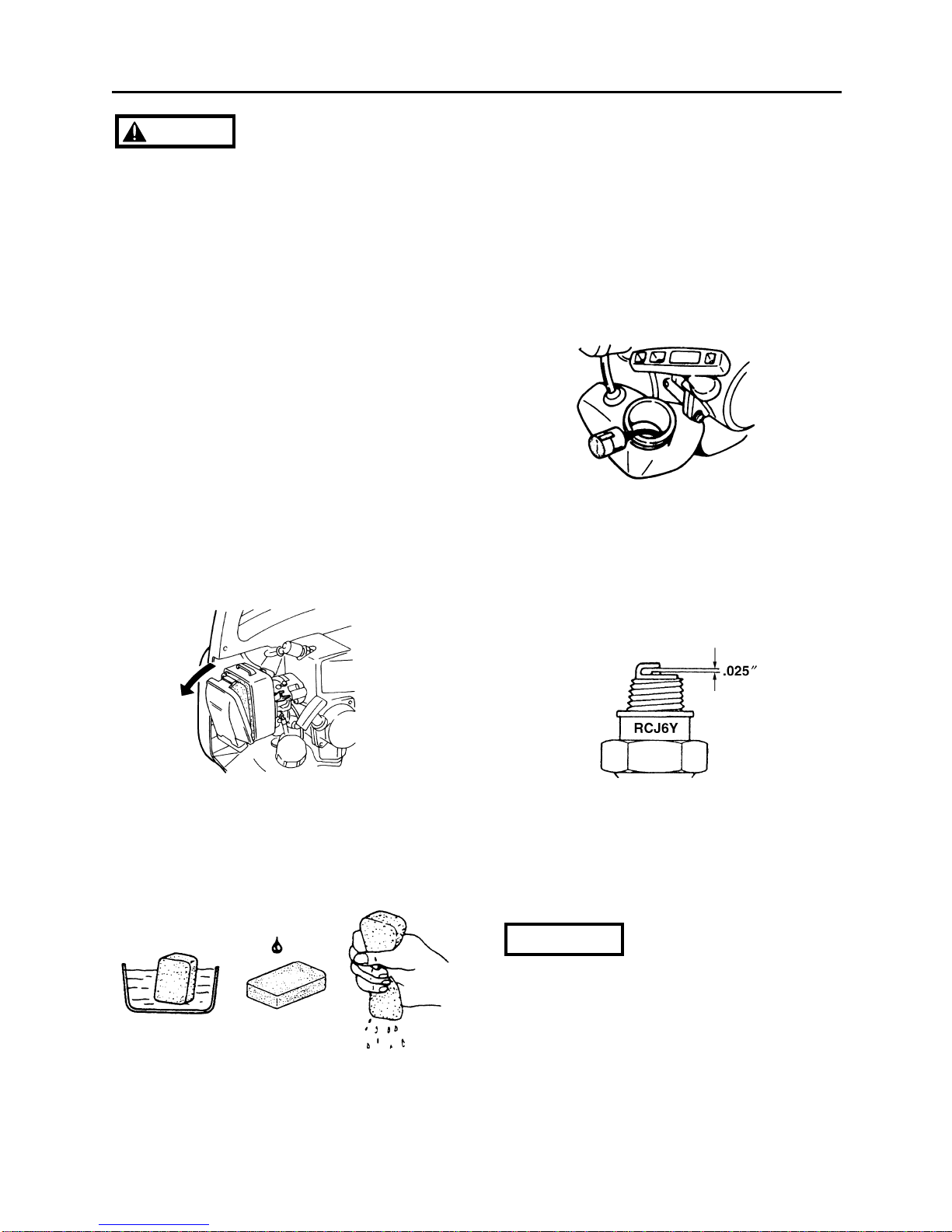
■SPARK PLUG
•The spark plug may gather carbon deposits
on its firing end with reasonable use.
Remove and inspect the spark plug every
25 hours and clean the electrodes as
necessary with a wire brush. The spark gap
should be adjusted to .025 in.
•Plug manufacturers recommend replacing
the plug twice a year to avoid unexpected
plug failure in a job.
REPLACEMENT PLUG IS A CHAMPION
RCJ6Y.
•Note that using any spark plugs other than
those designated may result in the engine
failing to operate properly or in the engine
becoming overheated and damaged.
•To install the spark plug, first turn the plug
until it is finger tight, then tighten it a
quarter turn more with a socket wrench.
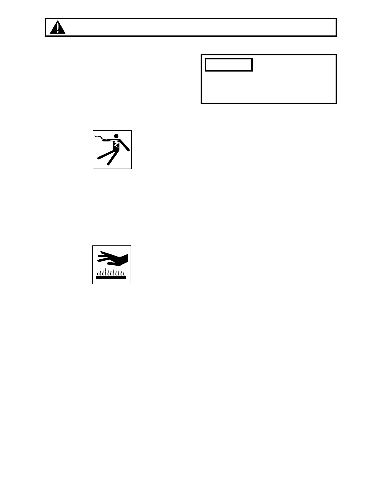
IMPORTANT
•Make sure that the engine has stopped
and is cool before performing any
service to the blower. Contact with
rotating blower fan or hot muffler may
result in a personal injury.
■AIR CLEANER
•Check the air cleaner every 25 hours of
use or more frequently if used under dusty
conditions. A clogged air filter may increase
fuel consumption while cutting down the
engine power. Never operate the blower
without the air filter or with a deformed filter
element because unfiltered dusty air will
quickly ruin the engine.
CLEANING AIR FILTER:
1.Remove the air cleaner cover by pulling
the tab on bottom and take out the filter
element.
2.Use neutral detergent and warm water to
clean the filter element. After cleaning, air
dry the element completely and moisten
with a small amount of motor oil.
3.Place the filter element into the air cleaner
housing and press the cover against the
housing until it clicks.