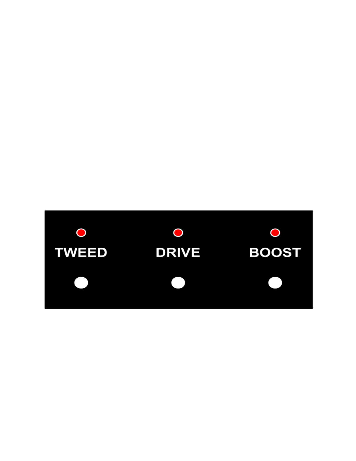
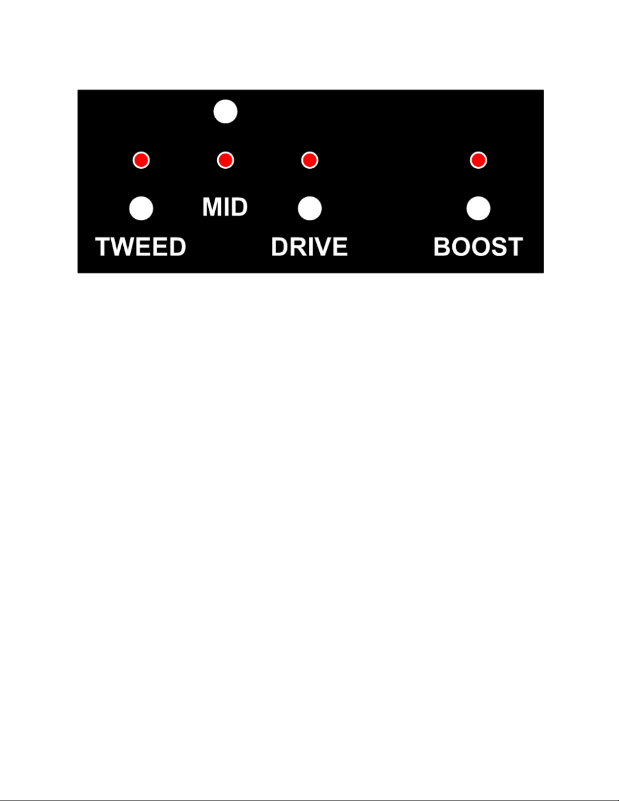
RedPlate Black-n-Blues Operations Guide
5
Rear Panel 45 Watt Export:
Rear Panel 100 Watt Export:
IEC Module –contains the main power switch, power cord inlet connector and the fuse drawer
which doubles as the voltage selector on export models. To access the fuse(s) use a small flat
blade screwdriver in the notch at the bottom of the power cord inlet connector, the drawer snaps
out in a rearward direction. The Black-n-Blues can accept both the larger (3AG footprint) or smaller
European (5mm X 20mm) fuses. A time delay variety (SLO-BLO) is recommended. For 45 watt
amplifiers a fuse in the range of 2.5 to 3 Amps is fine for domestic use (110 –125 VAC) and 1.25 to
1.5 amps is fine for Export use (220 –240 VAC). For 100 watt amplifiers a 5 amp fuse s is
recommended for domestic use (110 –125 VAC) and 2.5 amps should be used for Export use (220
–240 VAC). The fuse drawer can be rotated on the export models for voltage selection, make sure
the correct value fuse is located on the same side of the fuse drawer as the desired selection
arrow. Line up the appropriate arrow on the fuse drawer with the arrow on the bottom right of the
module for the proper VAC selection.
Standby Switch –This switch allows the tubes to warm up before operating the amplifier. Wait
1 minute after power on to move it up to the operate position. For improved tube life and
performance do not leave the amplifier in Standby position for longer than 20 minutes (better to just
leave it in operate mode during performance intermissions).
45 WATT / 18 WATT Switch (45 watt model only) –In 45 watt position the inside pair of
tubes is running fixed bias while the outside pair is running in cathode bias. In 18 watt position the
switch lifts the two fixed bias tubes leaving only the outside pair running in cathode bias mode. It is
alright to change the selection of this switch even when the amplifier is in operation
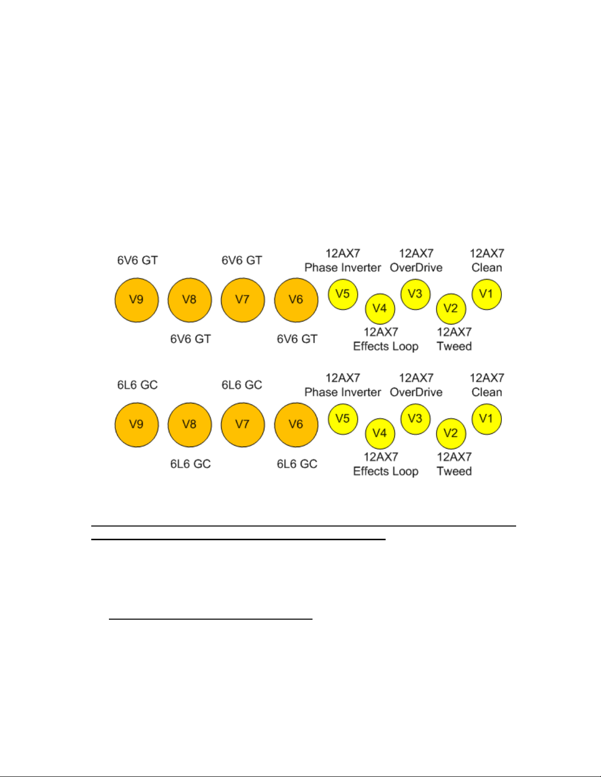
The 45 watt model will support the use of two 6L6 tubes as either an inside or outside pair (see
BIAS Section of this manual). DO NOT MIX 6L6 AND 6V6 TUBES.
100 WATT / 50 WATT Switch (100 watt model only) –This switch lessens the influence of
the inside pair of output tubes. It is alright to change the selection of this switch even when the
amplifier is in operation
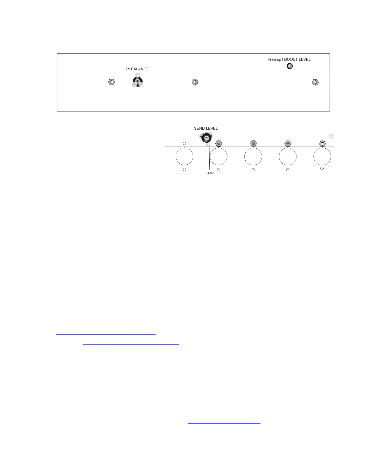
Bias adjustment and bias test point –Allows external access for bias adjustment (see bias
procedure in the Maintenance section).
LINE OUT –A line level signal jack derived from the speaker output which contains the whole
tone of the amplifier.
Speaker Jacks –The MAIN and EXT jacks are wired in parallel. The MAIN jack must be used
first because it has a protection device. ALWAYS HAVE A SPEAKER CONNECTED TO AVOID
PERMANENT AMPLIFIER AND OUTPUT TUBE DAMAGE.