RedPlate RP50R Operations Guide
3
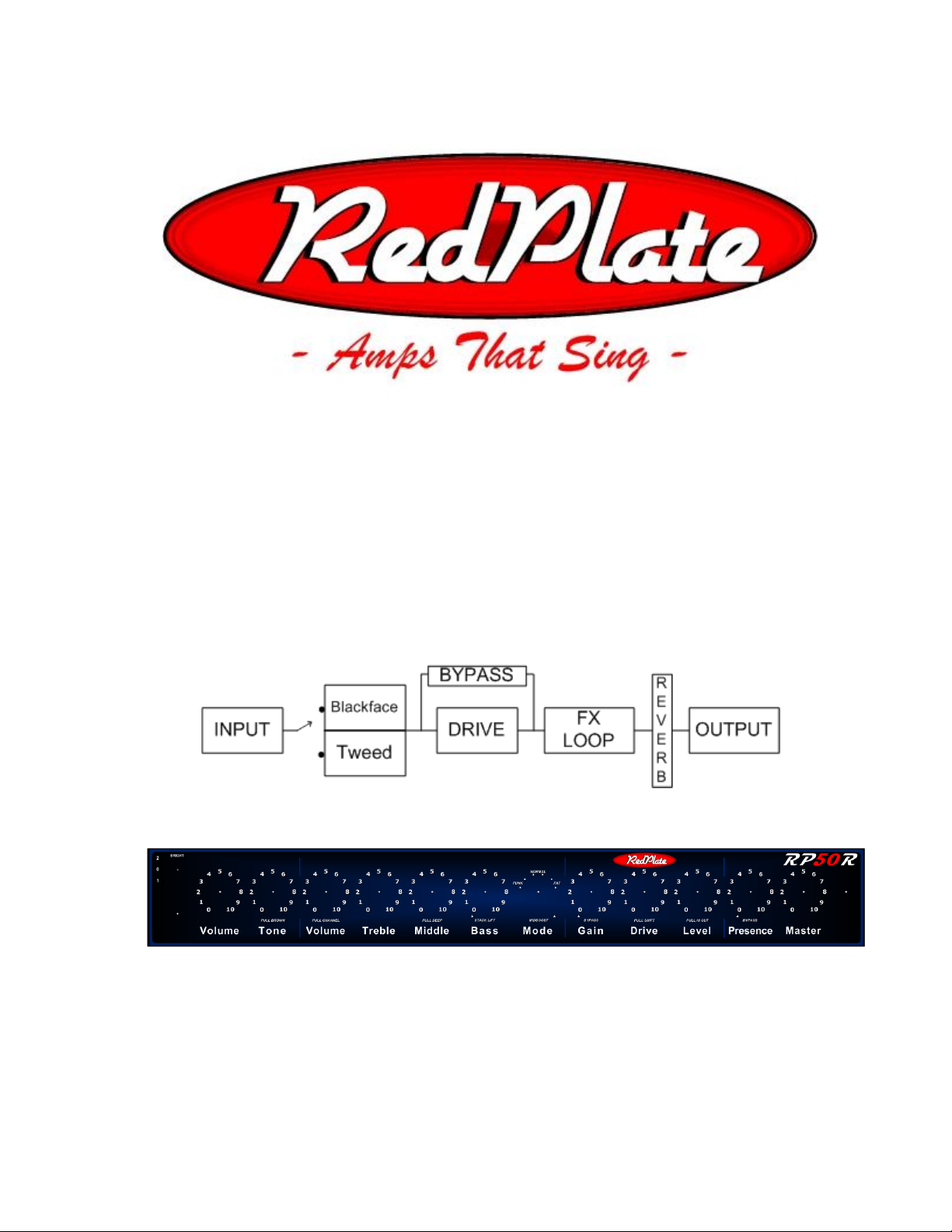
MASTER SECTION
Presence Master
Presence Control –The presence circuit uses global negative feedback to remove low
frequencies which frees up bandwidth for more midrange and highs. Think of it as a tone control to
balance the relationship between highs and lows, especially when the amplifier is naturally
producing increased low end at louder volumes. The control clicks off when rotated to zero for no
presence.
Master Volume –This is an active control and actually adds gain at the higher settings. The
cleanest tones are achieved at settings below 7.
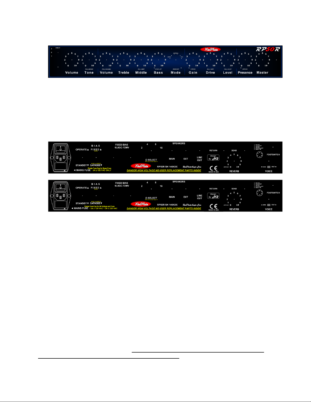
REAR PANEL SECTION
Domestic (USA):
Export:
IEC Module –contains the main power switch, power cord inlet connector and the fuse drawer
which doubles as the voltage selector on export models. To access the fuse(s) use a small flat
blade screwdriver in the notch at the bottom of the power cord inlet connector, the drawer snaps
out in a rearward direction. The RP50R can accept both the larger (3AG footprint) or smaller
European (5mm X 20mm) fuses. A time delay variety (SLO-BLO) is recommended. A fuse in the
range of 2.5 to 3 Amps is fine for domestic use (110 –125 VAC) and 1.25 to 1.5 amps is fine for
Export use (220 –240 VAC). The fuse drawer can be rotated on the export models for voltage
selection, make sure the correct value fuse is located on the same side of the fuse drawer as the
desired selection arrow. Line up the appropriate arrow on the fuse drawer with the arrow on the
bottom right of the module for the proper VAC selection.
Standby Switch –This switch allows the tubes to warm up before operating the amplifier. Wait
1 minute after power on to move it up to the operate position. For improved tube life and
performance do not leave the amplifier in Standby position for longer than 20 minutes (better to just
leave it in operate mode during performance intermissions).
FIXED/CATHODE (50 WATT / 40 WATT) Switch –This switch changes the bias architecture
of the output tubes from fixed bias (50 WATT) to cathode biased (40 WATT). The 40 WATT
position allows the use of 6V6 tubes for lower power output (~18 Watts with 6V6).
Bias adjustment and bias test point –Allows external access for bias adjustment (see bias
procedure in the Maintenance section).
Impedance Selector Ω - Set this to the total impedance of all attached speakers.
Speaker Jacks –The MAIN and EXT jacks are wired in parallel. The MAIN jack must be used
first because it has a protection device. ALWAYS HAVE A SPEAKER CONNECTED TO AVOID
PERMANENT AMPLIFIER AND OUTPUT TUBE DAMAGE.