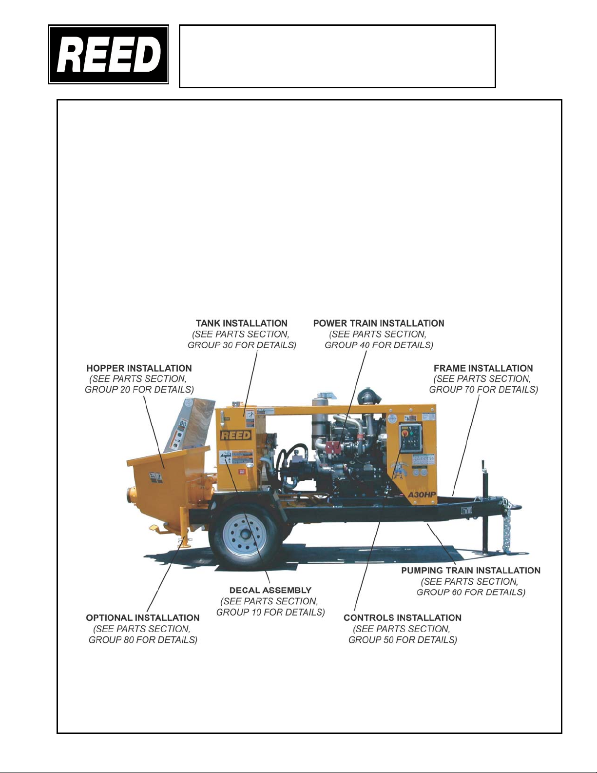
REED ROCK MASTER A30HP
TRAILER CONCRETE PUMP
OPER.
PAGE 09
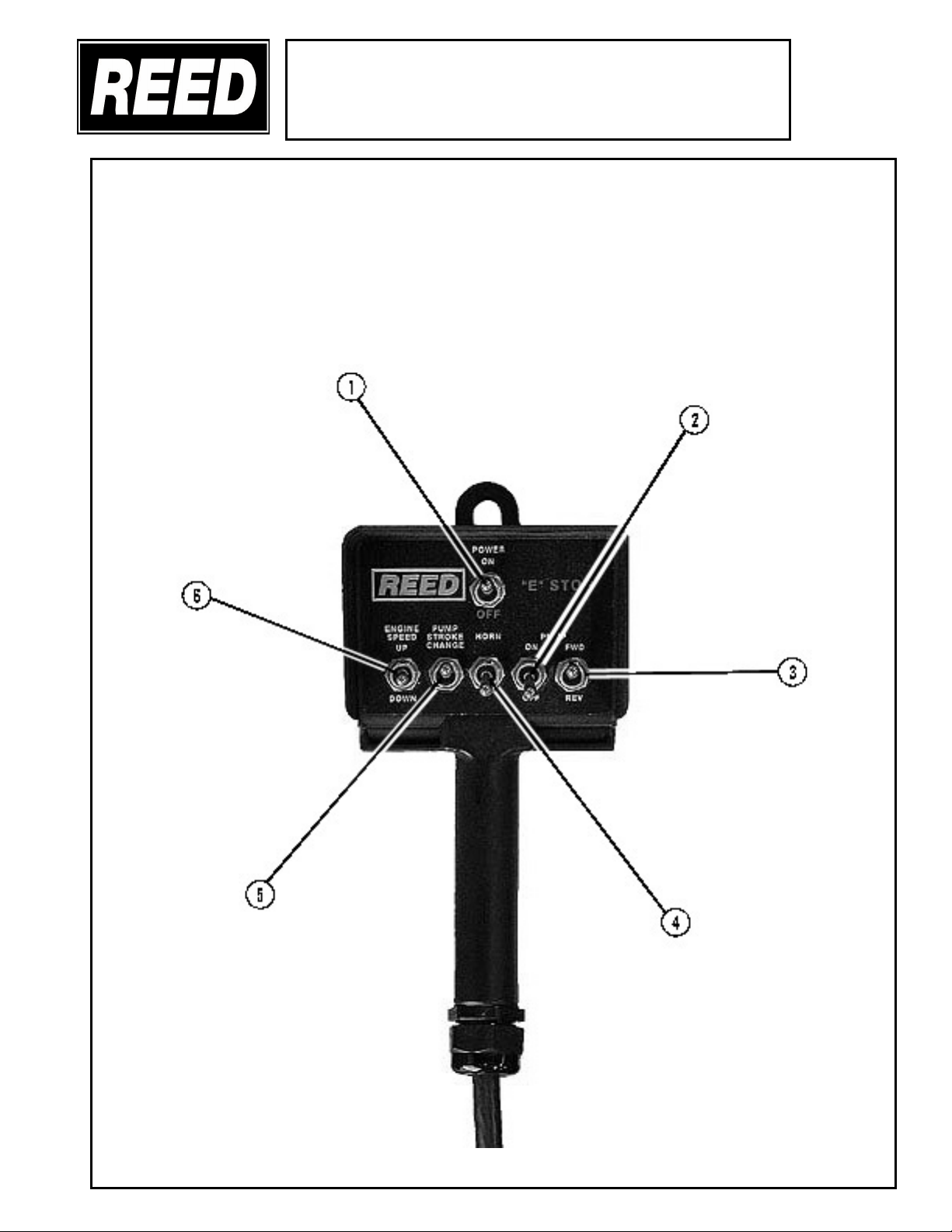
1. POWER ON OFF / E-STOP SWITCH
This is a three (2) position maintained toggle switch. This STOP switch is used to shut
down the pump cycle in an EMERGENCY situation. Move toggle in DOWN position in to
STOP operation of pump cycling. Move toggle to UP position to REACTIVATE system.
2. PUMP ON OFF SWITCH
This is a two (2) position toggle switch and is used to control the concrete pump. Move
toggle to UP position to activate PUMP-ON. Move toggle in DOWN position to turn
PUMP-OFF.
3. PUMP DIRECTION FORWARD AND REVERSE SWITCH
This is a two (2) position toggle switch and is used to control the cycle direction of the
concrete pump. Move toggle to UP position to activate FORWARD cycling. Move toggle
in DOWN position for REVERSE cycling.
4. HORN
This is a two (2) position momentary toggle switch and is used to activate the HORN and
reactivate the control and pump circuit after machine has been shut down using the
EMERGENCY STOP switch. Once the emergency stop has been depressed it will be
necessary to pull out on the EMERGENCY STOP switch and move toggle of
HORN/RESET switch momentary to RESET position and sound horn.
5. PUMP STROKE CHANGE SWITCH
This is a two (2) position spring return switch and has two functions. One is a momentary
toggle to change stroke from one side to the other to help clear a possible link plug. The
other function is when the switch is held DOWN and allow for end of stroke. High pressure
check or in the instance of equalizing the stroking pistons. The allowance of the spring
return sets the machine back in forward stroke.
6. ENGINE SPEED SWITCH
This is a three (3) position momentary return to center position toggle switch. It is used to
control and set the ENGINE speed. Activate the toggle switch UP and hole to INCREASE
RPM; move toggle to DOWN and hold to DECREASE RPM. Speed of engine will be
retained as set until reset. Center Position of switch is neutral.
REVISION: