Reelin PPC 14 Seer User manual

92-20522-45-03
SUPERSEDES 92-20522-45-02
HEAT PUMP OUTDOOR UNITS:
(-)PNE 13 SEER MODEL SERIES
(-)PPC 14 SEER MODEL SERIES
INSTALLATION INSTRUCTIONS
RECOGNIZE THIS SYMBOL AS AN INDICATION OF IMPORTANT SAFETY INFORMATION!
!
DO NOT DESTROY THIS MANUAL
PLEASE READ CAREFULLY AND KEEP IN A SAFE PLACE FOR FUTURE REFERENCE BY A SERVICEMAN
THESE INSTRUCTIONS ARE INTENDED AS AN AID TO
QUALIFIED, LICENSED SERVICE PERSONNEL FOR PROPER
INSTALLATION, ADJUSTMENT AND OPERATION OF THIS UNIT.
READ THESE INSTRUCTIONS THOROUGHLY BEFORE
ATTEMPTING INSTALLATION OR OPERATION. FAILURE TO FOL-
LOW THESE INSTRUCTIONS MAY RESULT IN IMPROPER
INSTALLATION, ADJUSTMENT, SERVICE OR MAINTENANCE
POSSIBLY RESULTING IN FIRE, ELECTRICAL SHOCK,
PROPERTY DAMAGE, PERSONAL INJURY OR DEATH.
WARNING
!
[ ] INDICATES METRIC CONVERSIONS
!WARNING
These instructions are intended as an aid to qualified, licensed ser-
vice personnel for proper installation, adjustment and operation of
this unit. Read these instructions thoroughly before attempting
installation or operation. Failure to follow these instructions may
result in improper installation, adjustment, service or maintenance
possibly resulting in fire, electrical shock, property damage, person-
al injury or death.

2
TABLE OF CONTENTS
1.0 SAFETY INFORMATION . . . . . . . . . . . . . . . . . . . . . . . . . . . . . . . . . . . . . . . . . . . . 3
2.0 GENERAL INFORMATION . . . . . . . . . . . . . . . . . . . . . . . . . . . . . . . . . . . . . . . . . . 4
2.1 Checking Product Received. . . . . . . . . . . . . . . . . . . . . . . . . . . . . . . . . . . . . . 4
2.2 Application . . . . . . . . . . . . . . . . . . . . . . . . . . . . . . . . . . . . . . . . . . . . . . . . . . . 4
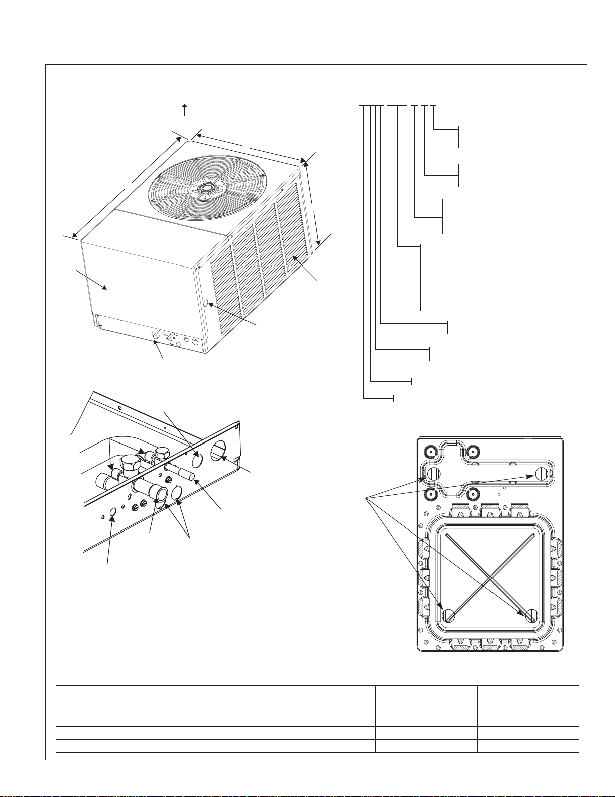
2.3 Dimensions . . . . . . . . . . . . . . . . . . . . . . . . . . . . . . . . . . . . . . . . . . . . . . . . . . 5
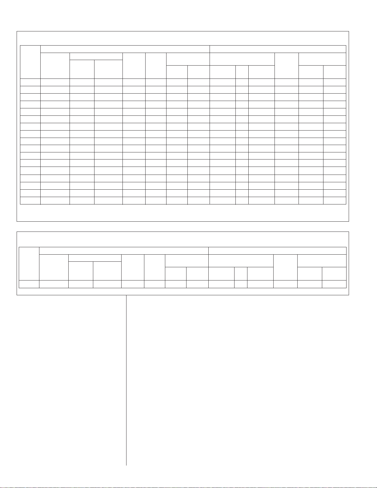
2.4 Electrical and Physical Data . . . . . . . . . . . . . . . . . . . . . . . . . . . . . . . . . . . . . 6
3.0 LOCATING UNIT . . . . . . . . . . . . . . . . . . . . . . . . . . . . . . . . . . . . . . . . . . . . . . . . . . 6
3.1 Corrosive Environment . . . . . . . . . . . . . . . . . . . . . . . . . . . . . . . . . . . . . . . . . 6
3.2 Heat Pump Location . . . . . . . . . . . . . . . . . . . . . . . . . . . . . . . . . . . . . . . . . . . 7
3.3 Operational Issues. . . . . . . . . . . . . . . . . . . . . . . . . . . . . . . . . . . . . . . . . . . . . 7
3.4 For Units With Space Limitations. . . . . . . . . . . . . . . . . . . . . . . . . . . . . . . . . . 7
3.5 Customer Satisfaction Issues . . . . . . . . . . . . . . . . . . . . . . . . . . . . . . . . . . . . 8
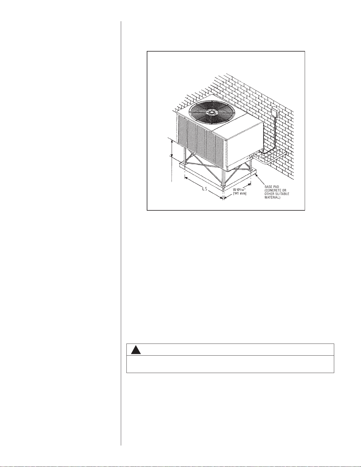
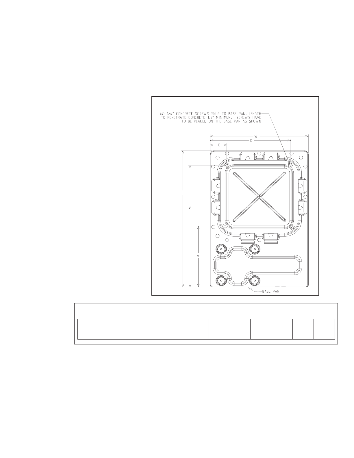
3.6 Unit Mounting. . . . . . . . . . . . . . . . . . . . . . . . . . . . . . . . . . . . . . . . . . . . . . . . . 8
3.7 Factory-Prepferred Tie-Down Method . . . . . . . . . . . . . . . . . . . . . . . . . . . . . . 8
4.0 REFRIGERANT CONNECTIONS . . . . . . . . . . . . . . . . . . . . . . . . . . . . . . . . . . . . . 9
5.0 REPLACEMENT UNITS. . . . . . . . . . . . . . . . . . . . . . . . . . . . . . . . . . . . . . . . . . . . . 9
6.0 INDOOR COIL . . . . . . . . . . . . . . . . . . . . . . . . . . . . . . . . . . . . . . . . . . . . . . . . . . . 10
6.1 Location . . . . . . . . . . . . . . . . . . . . . . . . . . . . . . . . . . . . . . . . . . . . . . . . . . . . 10
7.0 INTERCONNECTING TUBING . . . . . . . . . . . . . . . . . . . . . . . . . . . . . . . . . . . . . . 10
7.1 Vapor & Liquid Lines . . . . . . . . . . . . . . . . . . . . . . . . . . . . . . . . . . . . . . . . . . 10
7.2 Maximum Length of Lines . . . . . . . . . . . . . . . . . . . . . . . . . . . . . . . . . . . . . . 10
7.3 Outdoor Unit Installed Above Indoor Coil. . . . . . . . . . . . . . . . . . . . . . . . . . . 10
7.4 Outdoor Unit Installed Below Indoor Coil . . . . . . . . . . . . . . . . . . . . . . . . . . 11
7.5 Tubing Installation . . . . . . . . . . . . . . . . . . . . . . . . . . . . . . . . . . . . . . . . . . . . 11
7.6 Tubing Connections. . . . . . . . . . . . . . . . . . . . . . . . . . . . . . . . . . . . . . . . . . . 12
7.7 Leak Testing . . . . . . . . . . . . . . . . . . . . . . . . . . . . . . . . . . . . . . . . . . . . . . . . 12
8.0 DEMAND DEFROST CONTROL . . . . . . . . . . . . . . . . . . . . . . . . . . . . . . . . . . . . . 14
8.1 Defrost Initiation. . . . . . . . . . . . . . . . . . . . . . . . . . . . . . . . . . . . . . . . . . . . . . 14
8.2 Defrost Termination . . . . . . . . . . . . . . . . . . . . . . . . . . . . . . . . . . . . . . . . . . . 14
8.3 Temperature Sensors . . . . . . . . . . . . . . . . . . . . . . . . . . . . . . . . . . . . . . . . . 14
8.4 Test Mode . . . . . . . . . . . . . . . . . . . . . . . . . . . . . . . . . . . . . . . . . . . . . . . . . . 14
8.5 Trouble Shooting Demand Defrost . . . . . . . . . . . . . . . . . . . . . . . . . . . . . . . 14
8.6 High/Low Pressure Control Monitoring - Enhanced Defrost Control Only . . 15
8.7 Enhanced Feature Defrost Control Diagnositc Codes. . . . . . . . . . . . . . . . . 15
9.0 EVACUATION PROCEDURE . . . . . . . . . . . . . . . . . . . . . . . . . . . . . . . . . . . . . . . 15
10.0 START UP & PERFORMANCE . . . . . . . . . . . . . . . . . . . . . . . . . . . . . . . . . . . . . . 16
11.0 CHECKING AIRFLOW . . . . . . . . . . . . . . . . . . . . . . . . . . . . . . . . . . . . . . . . . . . . . 16
12.0 CHECKING REFRIGERANT CHARGE . . . . . . . . . . . . . . . . . . . . . . . . . . . . . . . . 16
12.1 Charging By Liquid Pressure . . . . . . . . . . . . . . . . . . . . . . . . . . . . . . . . . . . . 16
12.2 Charging By Weight. . . . . . . . . . . . . . . . . . . . . . . . . . . . . . . . . . . . . . . . . . . 17
12.3 Final Leak Testing . . . . . . . . . . . . . . . . . . . . . . . . . . . . . . . . . . . . . . . . . . . . 17
13.0 ELECTRICAL WIRING. . . . . . . . . . . . . . . . . . . . . . . . . . . . . . . . . . . . . . . . . . . . . 17
13.1 Power Wiring . . . . . . . . . . . . . . . . . . . . . . . . . . . . . . . . . . . . . . . . . . . . . . . . 17
13.2 Grounding . . . . . . . . . . . . . . . . . . . . . . . . . . . . . . . . . . . . . . . . . . . . . . . . . . 18
13.3 Control Wiring . . . . . . . . . . . . . . . . . . . . . . . . . . . . . . . . . . . . . . . . . . . . . . . 18
14.0 FIELD INSTALLED ACCESSORIES . . . . . . . . . . . . . . . . . . . . . . . . . . . . . . . . . . 18
14.1 Compressor Crankcase Heater . . . . . . . . . . . . . . . . . . . . . . . . . . . . . . . . . . 18
14.2 Hard Start Components . . . . . . . . . . . . . . . . . . . . . . . . . . . . . . . . . . . . . . . . 19
14.3 Time Delay Control (TDC) . . . . . . . . . . . . . . . . . . . . . . . . . . . . . . . . . . . . . . 19
14.4 Low Ambient Control (LAC) . . . . . . . . . . . . . . . . . . . . . . . . . . . . . . . . . . . . . 19
14.5 High Pressure Controls (HPC). . . . . . . . . . . . . . . . . . . . . . . . . . . . . . . . . . . 19
14.6 Enhanced Compressor Protection Kit – RXPG-A01 . . . . . . . . . . . . . . . . . . 19
15.0 TROUBLESHOOTING . . . . . . . . . . . . . . . . . . . . . . . . . . . . . . . . . . . . . . . . . . . . . 20
15.1 Electrical Checks Flow Chart . . . . . . . . . . . . . . . . . . . . . . . . . . . . . . . . . . . . 20
15.2 Cooling Mechanical Checks Flow Chart . . . . . . . . . . . . . . . . . . . . . . . . . . . 21
15.3 Heating Mechanical Checks Flow Chart . . . . . . . . . . . . . . . . . . . . . . . . . . . 22
15.4 Defrost Mechanical Checks Flow Chart. . . . . . . . . . . . . . . . . . . . . . . . . . . . 23
15.5 Subcooling Calculation . . . . . . . . . . . . . . . . . . . . . . . . . . . . . . . . . . . . . . . . 24
15.6 General Troubleshooting Chart . . . . . . . . . . . . . . . . . . . . . . . . . . . . . . . . . . 25
15.7 Service Analyzer Chart . . . . . . . . . . . . . . . . . . . . . . . . . . . . . . . . . . . . . . . . 26
16.0 WIRING DIAGRAMS . . . . . . . . . . . . . . . . . . . . . . . . . . . . . . . . . . . . . . . . . . . . . . 31

3
1.0 SAFETY INFORMATION
!WARNING
These instructions are intended as an aid to qualified, licensed service per-
sonnel for proper installation, adjustment and operation of this unit. Read
these instructions thoroughly before attempting installation or operation.
Failure to follow these instructions may result in improper installation, adjust-
ment, service or maintenance possibly resulting in fire, electrical shock, prop-
erty damage, personal injury or death.
!WARNING
The manufacturer’s warranty does not cover any damage or defect to the air
conditioner caused by the attachment or use of any components. Accessories
or devices (other than those authorized by the manufacturer) into, onto or in
conjunction with the air conditioner. You should be aware that the use of
unauthorized components, accessories or devices may adversely affect the
operation of the air conditioner and may also endanger life and property. The
manufacturer disclaims any responsibility for such loss or injury resulting
from the use of such unauthorized components, accessories or devices.
!WARNING
Disconnect all power to unit before starting maintenance. Failure to do so can
cause electrical shock resulting in severe personal injury or death.
CAUTION
When coil is installed over a finished ceiling and/or living area, it is
recommended that a secondary sheet metal condensate pan be
constructed and installed under entire unit. Failure to do so may result
in property damage.
!CAUTION
Single-pole contactors are used on all standard single-phase units up through
5 tons. Caution must be exercised when servicing as only one leg of the power
supply is broken with the contactor. Two pole contactors are used on some
three phase units.
!WARNING
Do not use oxygen to purge lines or pressurize system for leak test. Oxygen
reacts violently with oil, which can cause an explosion resulting in severe per-
sonal injury or death.
!WARNING
Turn off electric power at the fuse box or service panel before making any
electrical connections.
Also, the ground connection must be completed before making line voltage
connections. Failure to do so can result in electrical shock, severe personal
injury or death.
!WARNING
The unit must be permanently grounded. Failure to do so can cause electrical
shock resulting in severe personal injury or death.
!CAUTION
Secure elevated unit and elevating stand in order to prevent tipping. Failure to
do this may result in minor or moderate injury.

4
2.0 GENERAL
The information contained in this manual has been prepared to assist in the proper
installation, operation and maintenance of the heat pump equipment. Improper
installation, or installation not made in accordance with these instructions, can result
in unsatisfactory operation and/or dangerous conditions, and can cause the related
warranty not to apply.
Read this manual and any instructions packaged with separate equipment required
to make up the system prior to installation. Retain this manual for future reference.
To achieve optimum efficiency and capacity, the indoor cooling coils listed in the
heat pump specification sheet should be used.
2.1 CHECKING PRODUCT RECEIVED
Upon receiving unit, inspect it for any shipping damage. Claims for damage, either
apparent or concealed, should be filed immediately with the shipping company.
Check heat pump model number, electrical characteristics and accessories to
determine if they are correct. Check system components to make sure they are
properly matched.
2.2 APPLICATION
Before installing any heat pump equipment, a duct analysis of the structure and a
heat gain calculation must be made. A heat gain calculation begins by measuring
all external surfaces and openings that gain heat from the surrounding air and
quantifying that heat gain. A heat gain calculation also calculates the extra heat
load caused by sunlight and by humidity removal.
There are several factors that installers must consider.
• Outdoor unit location • Indoor unit blower speed
• Proper equipment evacuation • Supply and return air duct design and sizing
• Refrigerant charge • System air balancing
• Indoor unit air flow • Diffuser and return air grille location and sizing
!WARNING
The manufacturer’s warranty does not cover any damage or defect to the
air conditioner caused by the attachment or use of any components.
Accessories or devices (other than those authorized by the manufactur-
er) into, onto or in conjunction with the air conditioner. You should be
aware that the use of unauthorized components, accessories or devices
may adversely affect the operation of the air conditioner and may also
endanger life and property. The manufacturer disclaims any responsibility
for such loss or injury resulting from the use of such unauthorized compo-
nents, accessories or devices.
MATCH ALL COMPONENTS:
• OUTDOOR UNIT
• INDOOR COIL/METERING DEVICE
• INDOOR AIR HANDLER/FURNACE
• REFRIGERANT LINES

5
FIGURE 1
DIMENSIONS AND INSTALLATION CLEARANCES UNIT MODEL NUMBER EXPLANATION
(-)PNE – 036 J A Z
COOLING CONNECTION FITTING
Z - SWEAT WITH SCROLL
Z-COMPRESSOR
VARIATIONS
A - SERIES = FULLY-FEATURED
B - SERIES = COMPETITIVE
ELECTRICAL DESIGNATION
J = 208/230-1-60
C = 208/230-3-60
D = 460-3-60
COOLING CAPACITY
018 = 18,000 BTU/HR
024 = 24,000 BTU/HR
030 = 30,000 BTU/HR
036 = 36,000 BTU/HR
042 = 42,000 BTU/HR
048 = 48,000 BTU/HR
060 = 60,000 BTU/HR
TRADE BRAND
P = REMOTE HEAT PUMP
N = STANDARD EFFICIENCY (13 SEER)
N = (5 TON ONLY)
P = HIGH EFFICIENCY (14 SEER)
C = DESIGN SERIES R-22
E = DESIGN SERIES R-22
AIR INLETS
(LOUVERS)
ALLOW 120[305 mm]
MIN. CLEARANCE
3 SIDES
AIR DISCHARGE
ALLOW 600[1524 mm] CLEARANCE
ALLOW 240[610 mm]
ACCESS CLEARANCE
ACCESS
PANEL
L
W
H
ALTERNATE HIGH VOLTAGE
CONNECTION (KNOCKOUT)
1 11/320 [34 mm]
SERVICE
FITTINGS
LOW VOLTAGE
CONNECTION
7/8" [22 mm]
HIGH VOLTAGE
CONNECTION
111/32" [34 mm]
LIQUID LINE
CONNECTION
SERVICE ACCESS
TO ELECTRICAL &
VALVES ALLOW
24" [610 mm]
CLEARANCE
ONE SIDE
27/8" [73 mm] DIA.
ACCESSORY
KNOCKOUTS
VAPOR LINE
CONNECTION
HIGH PRESSURE
CONTROL
MANUAL RESET
(FIELD INSTALLED
ACCESSORY)
A-00003
DIMENSIONAL DATA
ALTERNATE HIGH VOLTAGE
CONNECTION (KNOCKOUT)
1 11⁄32" [34 mm]
ALLOW 24" [610 mm]
ACCESS CLEARANCE
ACCESS
PANEL
REQUIRED PUMP-UP
INSTALLATION
LOCATIONS
A-00002
BOTTOM VIEW SHOWING DEFROST CONDENSATE
DRAIN OPENINGS (\\\\\\
SHADED AREAS).
BASE PAN
HEAT PUMP
MODEL 018
19” [482] 19” [482] 29” [736]
44-3/8” [1127]
33” [838]
40-1/2” [1028] 44-3/8” [1127] 44-3/8” [1127]
27-5/8” [701] 31-1/2” [800] 31-1/2” [800] 31-1/2” [800]
024 030 036, 042, 048, 060
(-)PNE/
(-)PPC
HEIGHT “H” (INCHES) [mm]
LENGTH “L” (INCHES) [mm]
WIDTH“W” (INCHES) [mm]
AIR DISCHARGE
ALLOW 60” [1524 mm] CLEARANCE
AIR INLETS
(LOUVERS)
ALLOW 6" [153 mm]
MIN.CLEARANCE
3SIDES
H
W
2.3 DIMENSIONS (SEE FIGURE 1)
NOTE: SERVICE ACCESS
TO ELECTRICAL & VALVES
ALLOW 24” [610 mm]
CLEARANCE ON SIDE

6
TABLE 1
(-)PNE ELECTRICAL AND PHYSICAL DATA
Model
Number
(-)PNE-
Phase
Frequency
(Hz) Voltage
(Volts)
Rated Load
Amperes
(RLA)
Locked Rotor
Amperes
(LRA)
Fan Motor
Full Load
Amperes
(FLA)
Minimum
Circuit
Ampacity
Amperes Minimum
Amperes
Maximum
Amperes
Face Area
Sq. Ft. (m2)
No.
Rows CFM [L/s] Net
Oz. [g]
Shipping
Lbs. [kg]
R22
Oz. [g]
ELECTRICAL
Compressor Outdoor Coil
Fuse or HACR
Circuit Breaker Weight
PHYSICAL
018J*Z 1-60-208/2309.0/9.041 0.6 12/12 15/1520/20 11 [1.02] 1 1925[908] 74 [2098] 130 [59] 140 [63]
024J*Z 1-60-208/23012.5/12.5 540.8 17/17 20/20 25/2512.94 [1.2] 1 2475[1168] 90 [2552] 175[79.4] 185[83]
030J*Z 1-60-208/23018.1/18.172.5 0.8 24/24 30/30 40/40 20.13[1.87] 1 2650 [1251] 129 [3657] 200 [90.7] 210 [95]
036C*Z 3-60-208/230 42/42 77 0.8 19/19 25/2530/3023.01 [2.14] 1 3000 [1416] 139 [3941] 220 [99.8] 230 [104]
036D*Z 3-60-460 6.9390.49151523.01 [2.14] 1 3000 [1416] 139 [3941] 220 [99.8] 230 [104]
036J*Z 1-60-208/23020.5/20.5 88 0.8 27/27 35/35 45/4523.01 [2.14] 1 3000 [1416] 139 [3941] 220 [99.8] 230 [104]
042C*Z 3-60-208/23014.4/14.488 1.2 20/20 25/2530/3023.01 [2.14] 1 3575[1687] 146 [4139] 230 [104.3] 240 [108]
042D*Z 3-60-460 7.4440.610151523.01 [2.14] 1 3575[1687] 146 [4139] 230 [104.3] 240 [108]
042J*Z 1-60-208/23022.7/22.7 104 1.230/30 40/40 50/5023.01 [2.14] 1 3575[1687] 146 [4139] 230 [104.3] 240 [108]
048C*Z 3-60-208/23015.1911.2 20/20 25/2535/35 23.01 [2.14] 1 3575[1687] 155 [4394] 250 [113.4] 260 [117]
048D*Z 3-60-460 7.7460.611151523.01 [2.14] 1 3575[1687] 155 [4394] 250 [113.4] 260 [117]
048J*Z 1-60-208/23023.4/23.41371.231/31 40/40 50/5023.01 [2.14] 1 3575[1687] 155 [4394] 250 [113.4] 260 [117]
048Y*Z➀3-60-575TBD TBD TBD TBD TBD TBD 23.01 [2.14] 1 3575[1687] 155 [4394] 250 [113.4] 260 [117]
060C*Z 3-60-208/23017
.3/17.3 1231.223/2330/30 40/40 23.01 [2.14] 2 3350 [1581] 306 [8675] 280 [127] 290 [131]
060D*Z 3-60-460 6.749.5 0.610151523.01 [2.14] 2 3350 [1581] 306 [8675] 280 [127] 290 [131]
060J*Z 1-60-208/23025.0/25.0 148 1.233/33 40/40 50/5023.01 [2.14] 2 3350 [1581] 306 [8675] 280 [127] 290 [131]
060Y*Z➀3-60-575TBD TBD TBD TBD TBD TBD 23.01 [2.14] 2 3350 [1581] 306 [8675] 280 [127] 290 [131]
3.0 LOCATING UNIT
3.1 CORROSIVE ENVIRONMENT
The metal parts of this unit may be subject to rust or deterioration if exposed to a
corrosive environment. This oxidation could shorten the equipment’s useful life.
Corrosive elements include, but are not limited to, salt spray, fog or mist in seacoast
areas, sulphur or chlorine from lawn watering systems, and various chemical conta-
minants from industries such as paper mills and petroleum refineries.
If the unit is to be installed in an area where contaminants are likely to be a prob-
lem, special attention should be given to the equipment location and exposure.
• Avoid having lawn sprinkler heads spray directly on the unit cabinet.
• In coastal areas, locate the unit on the side of the building away from the water-
front.
• Shielding provided by a fence or shrubs may give some protection, but cannot
violate minimum airflow and service access clearances.
• Elevating the unit off its slab or base enough to allow air circulation will help
avoid holding water against the basepan.
Regular maintenance will reduce the build-up of contaminants and help to protect
the unit’s finish.
2.4 ELECTRICAL & PHYSICAL DATA (SEE TABLE 1 & 2)
➀ Electrical Data is not available at this time
TABLE 2
(-)PPC ELECTRICAL AND PHYSICAL DATA
Model
Number
(-)PPC-
Phase
Frequency
(Hz) Voltage
(Volts)
Rated Load
Amperes
(RLA)
Locked Rotor
Amperes
(LRA)
Fan Motor
Full Load
Amperes
(FLA)
Minimum
Circuit
Ampacity
Amperes Minimum
Amperes
Maximum
Amperes
Face Area
Sq. Ft. (m2)
No.
Rows CFM [L/s] Net
Lbs. [kg]
Shipping
Lbs. [kg]
Refrig.
Per
Circuit
Oz. [g]
ELECTRICAL
Compressor Outdoor Coil
Fuse or HACR
Circuit Breaker Weight
PHYSICAL
060JAZ 1-60-208-23025/25148 1.233/33 40/40 50/5023.01 [2.14] 2 3350 [1581] 295[8363]255 [115.7] 265[120.2]

• Frequent washing of the cabinet, fan blade and coil with fresh water will remove
most of the salt or other contaminants that build up on the unit.
• Regular cleaning and waxing of the cabinet with an automobile polish will pro-
vide some protection.
• A liquid cleaner may be used several times a year to remove matter that will not
wash off with water.
Several different types of protective coil coatings are offered in some areas. These
coatings may provide some benefit, but the effectiveness of such coating materials
cannot be verified by the equipment manufacturer.
3.2 HEAT PUMP LOCATION
Consult local and national building codes and ordinances for special installation
requirements. Following location information will provide longer life and simplified
servicing of the outdoor heat pump.
NOTE: These units must be installed outdoors. No ductwork can be attached, or
other modifications made, to the discharge grille. Modifications will affect perfor-
mance or operation.
3.3 OPERATIONAL ISSUES
•IMPORTANT: Locate the unit in a manner that will not prevent, impair or com-
promise the performance of other equipment horizontally installed in proximity
to the unit. Maintain all required minimum distances to gas and electric meters,
dryer vents, exhaust and inlet openings. In the absence of National Codes, or
manaufacturers’ recommendations, local code recommendations and require-
ments will take presidence.
• Refrigerant piping and wiring should be properly sized and kept as short as
possible to avoid capacity losses and increased operating costs.
• Locate the unit where water run off will not create a problem with the equip-
ment. Position the unit away from the drip edge of the roof whenever possible.
Units are weatherized, but can be affected by the following:
o Water from the junction of rooflines, without protective guttering, entering the
heat pump while in operation, can impact fan blade or motor life. Coil dam-
age may occur to a heat pump if moisture cannot drain from the unit under
freezing conditions.
o Freezing moisture, or sleeting conditions, can cause the cabinet to ice-over
prematurely and prevent heat pump operation, requiring backup heat, which
generally results in less economical operation.
• Closely follow clearance recommendations (see Figure 1).
o 24” to the service panel access
o 60” above heat pump fan discharge (unit top) to prevent recirculation
o 6” to heat pump coil grille air inlets (per heat pump).
3.4 FOR UNITS WITH SPACE LIMITATIONS
In the event that a space limitation exists, we will permit the following clearances:
Single Unit Applications: Heat pump grille side clearances below 6 inches will
reduce unit capacity and efficiency. Do not reduce the 60-inch discharge, or the 24-
inch service clearances.
Multiple Unit Applications: When multiple heat pump grille sides are aligned, a 6-
inch per unit clearance is recommended, for a total of 12 inches between multiple
units. Two combined clearances below 12 inches will reduce capacity and efficien-
cy. Do not reduce the 60-inch discharge, or 24-inch service clearances.
• Do not obstruct the bottom drain opening in the heat pump base pan. It is
essential to provide defrost condensate drainage to prevent possible refreezing
of the condensation. Provide a base pad for mounting the unit, which is slightly
pitched away from the structure. Route condensate off the base pad to an area
which will not become slippery and result in personal injury.
7
!WARNING
Disconnect all power to unit before starting maintenance. Failure to do so
can cause electrical shock resulting in severe personal injury or death.

8
• Where snowfall is anticipated, the heat pump must be elevated above the base
pad to prevent ice buildup that may crush the tubing of the heat pump coil or
cause fin damage. Heat pump units should be mounted above the average
expected accumulated snowfall for the area.
3.5 CUSTOMER SATISFACTION ISSUES
• The heat pump should be located away from the living, sleeping and recre-
ational spaces of the owner and those spaces on adjoining property.
• To prevent noise transmission, the mounting pad for the outdoor unit should
not be connected to the structure, and should be located sufficient distance
above grade to prevent ground water from entering the unit.
3.6 UNIT MOUNTING
If elevating the heat pump, either on a flat roof or on a slab, observe the
following guidelines. (See Figure 2.)
• The base pan provided elevates the heat pump 3/4” above the base pad.
• If elevating a unit on a flat roof, use 4” x 4” (or equivalent) stringers positioned
to distribute unit weight evenly and prevent noise and vibration.
NOTE: Do not block drain openings shown in Figure 1.
• If unit must be elevated because of anticipated snow fall, secure unit and ele-
vating stand such that unit and/or stand will not tip over or fall off.
3.7 FACTORY-PREFERRED TIE-DOWN METHOD
INSTRUCTIONS
IMPORTANT: These instructions are intended as a guide to securing equipment for
wind-load ratings of “120 MPH sustained wind load” and “3-second, 150 MPH gust.”
While this procedure is not mandatory, the Manufacturer does recommend that
equipment be properly secured in areas where high wind damage may occur.
STEP 1: Before installing, clear pad of any dirt or debris.
IMPORTANT: The pad must be constructed of industry-approved materials,
and must be thick enough to accommodate the concrete fastener.
FIGURE 2
RECOMMENDED ELEVATED INSTALLATION
!CAUTION
Secure elevated unit and elevating stand in order to prevent tipping.
Failure to do this may result in minor or moderate injury.
ELEVATION ABOVE
ANTICIPATED SNOW-
’FALL IS NECESSARY.
DO NOT BLOCK
OPENINGS IN BASE
PAN.REFER TO
FIGURE 1.

STEP 2: Center base pan on pad, ensuring it is level.
STEP 3: Using basepad as a guide, mark spots on concrete where 4 holes will be
drilled (see Figure 3).
STEP 4: Drill four pilot holes in pad, ensuring that the hole is at least 1/4” deeper
than the concrete screw being used.
STEP 5: Center basepan over pre-drilled holes and insert concrete screws.
STEP 6: Tighten concrete screws.
NOTE: Do not over-tighten the concrete screws. Doing so can weaken the
integrity of the concrete screw and cause it to break.
STEP 7: Finish unit assembly per unit’s installation instructions.
4.0 REFRIGERANT CONNECTIONS
All units are factory charged with Refrigerant 22. All models are supplied with ser-
vice valves. Keep tube ends sealed until connection is to be made to prevent sys-
tem contamination.
5.0 REPLACEMENT UNITS
To prevent failure of a new heat pump unit, the existing tubing system must be cor-
rectly sized and cleaned or replaced. Care must be exercised that the expansion
device is not plugged. For new and replacement units, a liquid line filter drier should
be installed and refrigerant tubing should be properly sized. Test the oil for acid. If
positive, a liquid line filter drier is mandatory.
9
FIGURE 3
SCREW LOCATIONS ON BASEPAN
TABLE 3
BASEPAN DIMENSIONS
MODEL NUMBER L W A B C D
(-)PNE/(-)PPC-018 37.625” 25.938” 15” 34” 3.5” 22.5”
(-)PNE/(-)PPC-024/030/036/042/048/060 41.5” 29.813” 15” 38” 3.5” 26.5”

10
6.0 INDOOR COIL
REFER TO INDOOR COIL MANUFACTURER’S INSTALLATION INSTRUC-
TIONS.
IMPORTANT: The manufacturer is not responsible for the performance and opera-
tion of a mismatched system, or for a match listed with another manufacturer’s coil.
6.1 LOCATION
Do not install the indoor coil in the return duct system of a gas or oil furnace.
Provide a service inlet to the coil for inspection and cleaning. Keep the coil pitched
toward the drain connection.
7.0 INTERCONNECTING TUBING
7.1 VAPOR AND LIQUID LINES
Keep all lines sealed until connection is made.
Make connections at the indoor coil first.
Refer to Line Size Information in Tables 3 through 5 for correct size and multipliers to
be used to determine capacity for various vapor line diameters and lengths of run.
The losses due to the lines being exposed to outdoor conditions are not included.
The factory refrigeration charge in the outdoor unit is sufficient for 15 feet of inter-
connecting lines. The factory refrigeration charge in the outdoor unit is sufficient for
the unit and 15 feet of standard size interconnecting liquid and vapor lines. For dif-
ferent lengths, adjust the charge as indicated below.
1/4” ± .3 oz. per foot
5/16” ± .4 oz. per foot
3/8” ± .6 oz. per foot
1/2” ± 1.2 oz. per foot
7.2 MAXIMUM LENGTH OF LINES
The maximum length of interconnecting line is 150 feet. Always use the shortest
length possible with a minimum number of bends. Additional compressor oil is not
required for any length up to 150 feet.
NOTE: Excessively long refrigerant lines cause loss of equipment capacity.
7.3 OUTDOOR UNIT INSTALLED ABOVE INDOOR COIL
Keep the vertical separation between coils to a minimum. However, the vertical dis-
tance can be as great as 120 feet with the condensing unit ABOVE the indoor coil.
Use the following guidelines when installing the unit:
1. DO NOT exceed 120 feet maximum vertical separation.
2. DO NOT change the flow check piston sizes if the vertical separation does not
exceed the values in Table 4.
3. Flow Check Piston Coil:
a. The vertical separation can be greater than the value in Table 4, but no
more than 120 feet.
b. If the separation height exceeds the Table value, reduce the indoor coil flow
check piston by two sizes plus one size for additional 10 feet beyond the
Table value.
CAUTION
When coil is installed over a finished ceiling and/or living area, it is
recommended that a secondary sheet metal condensate pan be
constructed and installed under entire unit. Failure to do so may result
in property damage.

11
4. Expansion Valve Coil:
a. The vertical separation can be greater than the Table value, but no more
than 120 feet.
b. No changes are required for expansion valve coils.
5. Capillary Tube Coil:
DO NOT exceed the Table values for vertical separation for capillary tube coils.
6. Always use the smallest liquid line size permitted to minimize the system
charge.
7. Table 4 may be used for sizing horizontal runs.
7.4 OUTDOOR UNIT BELOW INDOOR COIL
Keep the vertical separation to a minimum. Use the following guidelines when
installing the unit:
1. DO NOT exceed the vertical separations as indicated on Table 5.
2. Always use the smallest liquid line size permitted to minimize system charge.
3. No changes are required for either flow check piston coils or expansions coils.
4. Table 5 may be used for sizing horizontal runs.
7.5 TUBING INSTALLATION
Observe the following when installing correctly sized type “L” refrigerant tubing
between the condensing unit and evaporator coil:
• If a portion of the liquid line passes through a hot area where liquid refrigerant
can be heated to form vapor, insulating the liquid line is required.
• Use clean, dehydrated, sealed refrigeration grade tubing.
• Always keep tubing sealed until tubing is in place and connections are to be
made.
• Blow out the liquid and vapor lines with dry nitrogen before connecting to the
outdoor unit and indoor coil. Any debris in the line set will end up plugging the
expansion device.
• As an added precaution, a high quality, bi-directional filter drier is recommend-
ed to be installed in the liquid line, if not factory installed.
• Do not allow the vapor line and liquid line to be in contact with each other. This
causes an undesirable heat transfer resulting in capacity loss and increased
power consumption. The vapor line must be insulated.
• If tubing has been cut, make sure ends are deburred while holding in a position
to prevent chips from falling into tubing. Burrs such as those caused by tubing
cutters can affect performance dramatically, particularly on small liquid line
sizes.
• For best operation, keep tubing run as short as possible with a minimum num-
ber of elbows or bends.
• Locations where the tubing will be exposed to mechanical damage should be
avoided. If it is necessary to use such locations, the copper tubing should be
housed to prevent damage.
• If tubing is to be run underground, it must be run in a sealed watertight chase.
• Use care in routing tubing and do not kink or twist. Use a good tubing bender
on the vapor line to prevent kinking.
• Route the tubing using temporary hangers, then straighten the tubing and
install permanent hangers. Line must be adequately supported.
• The vapor line must be insulated to prevent dripping (sweating) and prevent
performance losses. Armaflex and Rubatex are satisfactory insulations for this
purpose. Use 1/2” minimum insulation thickness, additional insulation may be
required for long runs.
• Check Table 3 for the correct vapor line size. Check Tables 4 and 5 for the cor-
rect liquid line size.

12
7.6 TUBING CONNECTIONS
Indoor coils have only a holding charge of dry nitrogen. Keep all tube ends sealed
until connections are to be made.
• Use type “L” copper refrigeration tubing. Braze the connections with accepted
industry practices.
• Be certain both refrigerant shutoff valves at the outdoor unit are closed.
• Clean the inside of the fittings before brazing.
• Remove the cap and schrader core from service port to protect seals from heat
damage.
• Use an appropriate heatsink material around the copper stub and the service
valves before applying heat.
•IMPORTANT: Do not braze any fitting with the TEV sensing bulb attached.
• Braze the tubing between the outdoor unit and indoor coil. Flow dry nitrogen
into a service port and through the tubing while brazing.
• The service valves are not backseating valves. To open the valves, remove the
valve cap with an adjustable wrench. Insert a 3/16” or 5/16” hex wrench into the
stem. Back out counterclockwise.
• Replace the valve cap finger tight then tighten an additional 1/2 hex flat for a
metal-to-metal seal.
7.7 LEAK TESTING
• Pressurize line set and coil through service fittings with dry nitrogen to 150
PSIG maximum. Leak test all joints using liquid detergent. If a leak is found,
relieve pressure and repair.
TABLE 4
VAPOR LINE LENGTH SIZE AND CAPACITY MULTIPLIER
(-)PNE/(-)PPC
Unit Vapor Line
Connection Size
Vapor Line Run
- Feet
018 024 030 036 042 048 060
25
.98 .98 .98 .99 .99 .99 .99
1.00 1.00 1.00 1.00 1.00 1.00 1.00
1.01 1.01 1.01 1.01 1.01 1.01 1.01
.96 .96 .96 .97 .97 .97 .97
.99 .99 .99 .99 .99 1.00 .99
1.00 1.00 1.00 1.01 1.01 1.01 1.01
—— — — — — —
.98 .97 .95 .97 .96 .99 .98
1.00 .98 .97 .99 .99 1.00 .99
.93 .93 — — — .96 .95
.99 .98 .97 .98 .98 .99 .99
1.00 .99 .99 1.00 1.00 1.00 1.00
Opt.
Std.
Opt.
Opt.
Std.
Opt.
Opt.
Std.
Opt.
Opt.
Std.
Opt.
50
100
150
5/8 O.D. Optional
3/4 O.D. Optional
7/8 O.D. Optional
3/4 L.D. Sweat
3/4 O.D. Optional
7/8 O.D. Optional
1-1/8 O.D. Optional
7/8 L.D. Sweat
7/8 O.D. Optional
1-1/8 O.D. Optional
1-3/8 O.D. Optional
1-1/8 L.D. Sweat (4)
NOTES: 1) Capacity Multiplier x Rated Capacity = Actual Capacity. 2) Additional compressor oil is not required for runs up to 150 feet.
3) Oil traps in vertical runs are not required for any height up to 125 feet. See Liquid Line charts for Vertical Separation Requirements
and Limitations. 4) Adapter to 1-1/8 Factory Supplied.
!WARNING
Do not use oxygen to purge lines or pressurize system for leak test.
Oxygen reacts violently with oil, which can cause an explosion resulting in
severe personal injury or death.

13
NOTES:
*Standard line size. 1) This chart is applicable for heat pumps. 2) If the separation height exceeds the table values, reduce the indoor coil flow-check piston two
sizes plus one size for each additional 10 feet. Example: A 5 ton heat pump with a total line length of 100 feet with a vertical separation of 93 feet
utilizing a 3/8” liquid line: Table = 72 feet maximum vertical separation for 100 feet run. Separation exceeds table by (93-72) = 21 feet. Therefore, reduce the
indoor coil flow-check piston 2 + 2 = 4 sizes (for example, a #89 piston would reduce to a #85 piston). Increase the outdoor flow-check piston 2 + 2 = 4 sizes (for
example, a #56 would increase to a #60). 3) Do not exceed 120 feet maximum vertical separation. 4) No changes are required for expansion valve coils.
5) Always use the smallest liquid line possible to minimum system charge. 6) For heat pumps with vertical separation, do not insulate liquid line. 7) Chart may be
used to size horizontal runs.
TABLE 5
LIQUID LINE SIZE — OUTDOOR UNIT ABOVE INDOOR COIL
TABLE 6
LIQUID LINE SIZE — OUTDOOR UNIT BELOW INDOOR COIL
NOTES:
*Standard line size. 1) This chart is applicable for heat pumps. 2) Heat pumps with any vertical separation require the use of standard line sizes only, due to the
possibility of charge imbalance between heating and cooling modes. Example 1: A 3 ton heat pump with a total line length of 50 feet can have a maximum vertical
separation of 23 feet. Do not increase line size to 3/8”. 3) This chart may also be used to size horizontal runs. Example 2: A 1.5 ton heat pump can have a total
horizontal line length of 150 feet when using the 5/16” liquid line size. No vertical separation allowed. 4) Do not exceed vertical separation as indicated on the
chart. 5) Always use the smallest liquid line possible to minimize system charge. 6) No changes required for flow-check pistons or expansion valve coils.
Model
Line
Size
(Inch O.D.)
018 1/4* 25 50 70
5/16 0 0 0 0
024 1/4* 25 50
5/16 0 0 0 0 0
1/4* 25 50
030 5/16 0 0 0 0
3/8 0 0
036 5/16* 25 50 70
3/8 0 0 0 0
042 5/16* 25 50 75
3/8 0 0 0 0
048 3/8* 25 44 53 61 70
1/2 0 0
060 3/8* 25 46 61 72
1/2 0 0 0
TOTAL LENGTH - (ft)
25 50 75 100 125 150
VERTICAL SEPARATION - (ft)
Liquid Line
Size
(Inch I.D.)
Connection
5/16
5/16
5/16
5/16
5/16
5/16
5/16
5/16
5/16
5/16
5/16
3/8
3/8
3/8
3/8
Model
Line
Size
(Inch O.D.)
TOTAL LENGTH - (ft)
25 50 75 100 125 150
VERTICAL SEPARATION - (ft)
018 1/4* 25 23 8
5/16 0 0 0 0
024 1/4* 25 23
5/16 0 0 0 0 0
1/4* 25 23
030 5/16 0 0 0 0
3/8 0
036 5/16* 25 23 9
3/8 0 0 0 0
042 5/16* 25 23 9
3/8 0 0 0 0
048 3/8* 25 28 19 11 3
1/2 0 0
060 3/8* 25 23 11 3
1/2 0 0 0
Connection
Size
(Inch I.D.)
Liquid Line
5/16
5/16
5/16
5/16
5/16
5/16
5/16
5/16
5/16
5/16
5/16
3/8
3/8
3/8
3/8
— — — —
— — — ——
— — — —
— —
— — — —
— — — —
— —
— — —
— — — —
— — — — —
— — — —
—
— — — —
— — — —
— —
— — —

14
8.0 DEMAND DEFROST CONTROL
The demand defrost control is a printed circuit board assembly consisting of solid
state control devices with electro-mechanical outputs. The demand defrost control
monitors the outdoor ambient temperature, outdoor coil temperature, and the com-
pressor run-time to determine when a defrost cycle is required.
Standard Defrost Control (part number 47-21517-16): Found in units with model
numbers ending in “BZ”.
Enhanced Feature Demand Defrost Control (part number 47-21517-22): Found
in units with model numbers ending in “AZ” and units equipped with the field
installed Enhanced Compressor Protection Kit (RXPG-A01). Has high and low
pressure control inputs with unique pressure switch logic built into the microproces-
sor to provide compressor and system protection without nuisance lock-outs.
Cycles the compressor off for 5 seconds and the beginning and end of the defrost
cycle to eliminate the increased compressor noise caused by rapidly changing sys-
tem pressures when the reversing valve switches. See section 8.7 for diagnostic
flash codes for the two diagnostic LED’s provided on the control.
8.1 DEFROST INITIATION
A defrost will be initiated when the three conditions below are satisfied:
1) The outdoor coil temperature is below 35°F.
2) The compressor has operated for at least 34 minutes with the outdoor coil tem-
perature below 35°F.
3) The measured difference between the ambient temperature and the outdoor
coil temperature is greater than the calculated delta T.
Additionally, a defrost will be initiated if six hours of accumulated compressor run-
time has elapsed without a defrost with the outdoor coil temperature below 35°F.
8.2 DEFROST TERMINATION
Once a defrost is initiated, the defrost will continue until fourteen minutes has
elapsed or the coil temperature has reached the terminate temperature. The termi-
nate temperature is factory set at 70°F, although the temperature can be changed
to 50°F, 60°F, 70°F or 80°F by relocating a jumper on the board.
8.3 TEMPERATURE SENSORS
The coil sensor is clipped to the top tube on the outdoor coil at the point feed by the
distribution tubes from the expansion device (short 3/8” dia. tube). The air sensor is
located on the defrost control board.
If the ambient sensor fails the defrost control will initiate a defrost every 34 minutes
with the coil temperature below 35°F.
If the coil sensor fails the defrost control will not initiate a defrost.
8.4 TEST MODE
The test mode is initiated by shorting the TEST pins. In this mode of operation, the
enable temperature is ignored and all timers are sped up by a factor of 240. To initi-
ate a manual defrost, short the TEST pins. Remove the short when the system
switches to defrost mode. The defrost will terminate on time (14 minutes) or when
the termination temperature has been achieved. Short TEST pins again to termi-
nate the defrost immediately.
8.5 TROUBLE SHOOTING DEMAND DEFROST
Set the indoor thermostat select switch to heat and thermostat lever to a call for
heat.
Jumper the “test pins” to put the unit into defrost. If the unit goes into defrost and
comes back out of defrost, the indication is that the control is working properly.
If the unit did not go into defrost using the test pins, check to ensure that 24V is
being supplied to the control board. If 24V is present then replace the control.

8.6 HIGH/LOW PRESSURE CONTROL MONITORING - ENHANCED
DEFROST CONTROL ONLY
(Units with Model Numbers Ending with “AZ”)
Status of high and low pressure controls is monitored by the enhanced feature
demand defrost control and the following actions are taken.
High Pressure Control – Provides active protection in both cooling and heating
modes at all outdoor ambient temperatures. The high pressure control is an auto-
matic reset type and opens at approximately 440 psig and closes at approximately
270 psig. The compressor and fan motor will stop when the high pressure control
opens and will start again if the high side pressure drops to approximately 270 psig
when the automatic reset high pressure control resets. If the high pressure control
opens 3 times within a particular call for heating or cooling operation, the defrost
control will lock out compressor and outdoor fan operation.
Low Pressure Control – Provides active protection in both heating and cooling
modes at all outdoor ambient temperatures. The low pressure control is an auto-
matic reset type and opens at approximately 7 psig and closes at approximately 22
psig. Operation is slightly different between cooling and heating modes.
Cooling Mode: the compressor and fan motor will stop when the low pressure
control opens and will start again when the low side pressure rises to approxi-
mately 22 psig and the low pressure control automatically resets. If the low
pressure switch open 3 times within a particular call for cooling operation, the
defrost control will lock out compressor and outdoor fan operation.
Heating Mode: The compressor and fan motor will stop when the low pres-
sure control opens and will start again when the low side pressure rises to
approximately 22 psig and the low pressure control automatically resets. If the
low pressure switch trips 3 times within 120 minutes of operation during a par-
ticular call for heating operation, the defrost control will lock out compessor and
outdoor fan operation. If the lock-out due to low pressure occurs at an outdoor
ambient temperature below 5°F, the defrost control will automatically exit the
lock-out mode when the outdoor ambient temperature rises to 5°F. This fea-
ture is necessary since the low pressure control could possibly have opened
due to the outdoor ambient being very low rather than an actural system fault.
Exiting Lock-Out Mode: To exit the lock-out mode, remove 24 volts to the defrost
control by removing power to the indoor air-handler/furnace or by shorting the two
defrost control test pins together.
8.7 ENHANCED FEATURE DEFROST CONTROL DIAGNOSTIC CODES
9.0 EVACUATION PROCEDURE
The life and efficiency of the equipment is dependent upon the thoroughness exer-
cised by the technician when evacuating air and moisture from the system.
Air in the system causes high condensing temperatures and pressure, resulting in
increased power input and non-verifiable performance.
Moisture chemically reacts with the refrigerant and oil to form corrosive hydrofluoric
and hydrochloric acids. These attack motor windings and parts, causing breakdown.
15
LED 1 LED 2 Control Board Status
OFF OFF No Power
ON ON Coil Sensor Failure
OFF ON Ambient Sensor Failure
FLASH FLASH Normal
OFF FLASH Low Pressure Lockout (short test pins to reset)
FLASH OFF High Pressure Lockout (short test pins to reset)
ON FLASH Low Pressure Control Open
FLASH ON High Pressure Control Open
Alternate Flashing 5 Minute Time Delay

16
After the system has been leak checked and proven sealed, connect the vacuum
pump and evacuate system to 500 microns. The vacuum pump must be connected
to both the high and low sides of the system through adequate connections. Use
the largest size connections available since restrictive service connections may lead
to false readings because of pressure drop through the fittings.
IMPORTANT: Compressors (especially scroll type) should never be used to evacu-
ate the heat pump system because internal electrical arcing may result in a dam-
aged or failed compressor.
10.0 START UP AND PERFORMANCE
Even though the unit is factory-charged with Refrigerant-22 (R-22), the charge must
be checked to the charge table on the service panel and adjusted, if required. (See
Table 1.) Allow the unit to run for a minimum of five minutes. Before analyzing
charge, see the instructions on the unit service panel rating plate for marking the
total charge.
11.0 CHECKING AIRFLOW
The air distribution system has the greatest effect on airflow. The duct system is
totally controlled by the contractor. For this reason, the contractor should use only
industry-recognized procedures.
Heat pump systems require a specified airflow. Each ton of cooling requires
between 350 and 450 cubic feet of air per minute (CFM), or 400 CFM nominally.
Duct design and construction should be carefully done. System performance can be
lowered dramatically through bad planning or workmanship.
Air supply diffusers must be selected and located carefully. They must be sized and
positioned to deliver treated air along the perimeter of the space. If they are too
small for their intended airflow, they become noisy. If they are not located properly,
they cause drafts. Return air grilles must be properly sized to carry air back to the
blower. If they are too small, they also cause noise.
The installers should balance the air distribution system to ensure proper quiet air-
flow to all rooms in the home. This ensures a comfortable living space.
An air velocity meter or airflow hood can give a reading of the system CFM’s.
12.0 CHECKING REFRIGERANT CHARGE
Charge for all systems should be checked against the Charging Chart inside the
access panel cover.
IMPORTANT: Do not operate the compressor without charge in system.
Addition of R-22 will raise pressures (vapor, liquid and discharge).
If adding R-22 raises both vapor pressure and temperature, the unit is overcharged.
IMPORTANT: Use industry-approved charging methods to ensure proper system
charge.
12.1 CHARGING BY LIQUID PRESSURE
Liquid pressure method is used for charging systems in the cooling and heating
mode. The service port on the liquid service valve (small valve) and suction (large
valve) is used for this purpose.
Verify that the outdoor unit is running and the indoor air mover is delivering the
maximum airflow for this system size. Read and record the outdoor ambient tem-
perature. Read and record the liquid and suction pressures at the ports on the liquid
and suction valves. If refrigerant lines are sized using the nameplate charge, the
correct liquid pressure is found at the intersection of the suction pressure and the
outdoor ambient.
1. Remove refrigerant charge if the liquid pressure is above the chart value.
2. Add refrigerant charge if the liquid pressure is below the chart value.

12.2 CHARGING BY WEIGHT
For a new installation, evacuation of interconnecting tubing and indoor coil is ade-
quate; otherwise, evacuate the entire system. Use the factory charge shown in
Tables 1 through 5 of these instructions or unit data plate. Note that charge value
includes charge required for 15 ft. of standard size interconnecting liquid line.
Calculate actual charge required with installed liquid line size and length using:
1/4” O.D. = .3 oz./ft.
5/16” O.D. = .4 oz./ft.
3/8” O.D. = .6 oz./ft.
1/2” O.D. = 1.2 oz./ft.
With an accurate scale (+/– 1 oz.) or volumetric charging device, adjust charge dif-
ference between that shown on the unit data plate and that calculated for the new
system installation. If the entire system has been evacuated, add the total calculat-
ed charge.
12.3 FINAL LEAK TESTING
After the unit has been properly evacuated and charged, a halogen leak detector
should be used to detect leaks in the system. All piping within the condensing unit,
evaporator, and interconnecting tubing should be checked for leaks. If a leak is
detected, the refrigerant should be recovered before repairing the leak. The Clean
Air Act prohibits releasing refrigerant into the atmosphere.
13.0 ELECTRICAL WIRING
Field wiring must comply with the National Electric Code (C.E.C. in Canada) and
any applicable local code.
13.1 POWER WIRING
It is important that proper electrical power from a commercial utility is available at
the condensing unit contactor. Voltage ranges for operation are shown in Table 6.
Install a branch circuit disconnect within sight of the unit and of adequate size to
handle the starting current (see Table 1).
Power wiring must be run in a rain-tight conduit. Conduit must be run through the
connector panel below the access cover (see Figure 1) and attached to the bottom
of the control box.
Connect power wiring to contactor located in outdoor condensing unit electrical box.
(See wiring diagram attached to unit access panel.)
Check all electrical connections, including factory wiring within the unit and make
sure all connections are tight.
DO NOT connect aluminum field wire to the contactor terminals.
17
!WARNING
Turn off electric power at the fuse box or service panel before making any
electrical connections.
Also, the ground connection must be completed before making line volt-
age connections. Failure to do so can result in electrical shock, severe
personal injury or death.
TABLE 7
VOLTAGE RANGES (60 HZ)
Operating Voltage Range at Copeland
Nameplate Voltage Maximum Load Design Conditions for
Compressors
208/230 (1 Phase) 197 - 253
208/230 (3 Phase) 187 - 253
460 414 - 506
575 517 633
!CAUTION
Single-pole contactors are used on all standard single-phase units up
through 5 tons. Caution must be exercised when servicing as only one leg
of the power supply is broken with the contactor. Two pole contactors are
used on some three phase units.

18
13.2 GROUNDING
A grounding lug is provided near the contactor for a ground wire.
13.3 CONTROL WIRING
(See Figure 4)
If the low voltage control wiring is run in conduit with the power supply, Class I insu-
lation is required. Class II insulation is required if run separate. Low voltage wiring
may be run through the insulated bushing provided in the 7/8 hole in the base
panel, up to and attached to the pigtails from the bottom of the control box. Conduit
can be run to the base panel if desired by removing the insulated bushing.
A thermostat and a 24 volt, 40 VA minimum transformer are required for the control
circuit of the condensing unit. The furnace or the air handler transformer may be
used if sufficient. See the wiring diagram for reference. Use Table 7 to size the 24
volt control wiring.
14.0 FIELD INSTALLED ACCESSORIES
14.1 COMPRESSOR CRANKCASE HEATER (CCH)
While scroll compressors usually do not require crankcase heaters, there are
instances when a heater should be added. Refrigerant migration during the off cycle
can result in a noisy start up. Add a crankcase heater to minimize refrigeration
migration, and to help eliminate any start up noise or bearing “wash out.”
NOTE: The installation of a crankcase heater is recommended if the system charge
exceeds the values in Table 9. All 3-phase models come standard with a
crankcase heater factory installed.
SOLID COPPER WIRE - AWG.
3.0 16 14 12 10 10 10
2.5 16 14 12 12 10 10
2.0 18 16 14 12 12 10
50 100 150 200 250 300
Length of Run - Feet (1)
Thermostat Load - Amps
(1) Wire length equals twice the run distance.
NOTE: Do not use control wiring smaller than No. 18 AWG between thermostat and outdoor unit.
TABLE 8
FIELD WIRE SIZE FOR 24 VOLT THERMOSTAT CIRCUITS
!WARNING
The unit must be permanently grounded. Failure to do so can cause elec-
trical shock resulting in severe personal injury or death.
FIGURE 4
CONTROL WIRING FOR AIR HANDLER
B
W2
G
Y
W1
B
ODD
C
R
Air Handler
Y
G
W2
E
Heat Pump Thermostat
Heat Pump
Outdoor Unit
CR
Y
B
R
D
C
Y
Field Installed
Line Voltage
-
WIRING INFORMATION
Factory Standard
-
WH/BL
GR/BK
YL
WH/BK
GR/YL
BR
BL
RD
YL/BL
Optional Field Installed Jumper (see note 1)
1
*
*
*2
*Not present on all
air-handler models.
OPTIONAL
- 1 STAGE HEAT
YL
BR
BL
RD
PR
NOTES:
1. Jumper “E” to “W2” on
thermostat to transfer
control of supplemental
heat to 1st stage when
the emergency heat
switch is on.
2. This wire turns on elec-
tric heat strip during
defrost, omit for most
economical operation.
WIRE COLOR CODE
BK = BLACK
BL = BLUE
BR = BROWN
GR = GREEN
PR = PURPLE
RD = RED
WH = WHITE
YL = YELLOW

19
All heaters are located on the lower half of the compressor shell. Its purpose is to
drive refrigerant from the compressor shell during long off cycles, thus preventing
damage to the compressor during start-up.
At initial start-up or after extended shutdown periods, make sure the heater is ener-
gized for at least 12 hours before the compressor is started. (Disconnect switch on
and wall thermostat off.)
14.2 HARD START COMPONENTS
Start components are not usually required with the scroll compressors used in
(-)PNE heat pumps, but are available for special cases and where start components
are desirable to reduce light dimming.
NOTE: Hard start components are standard on (-)PNE/(-)PPC****AZ models.
14.3 TIME DELAY CONTROL (TDC)
The time delay (TDC) is in the low voltage control circuit. When the compressor
shuts off due to a power failure or thermostat operation, this control keeps it off at
least 5 minutes which allows the system pressure to equalize, thus not damaging
the compressor or blowing fuses on start-up.
14.4 LOW AMBIENT CONTROL (LAC)
This component senses compressor head pressure and shuts the heat pump fan off
when the head pressure drops to approximately 150 PSIG. This allows the unit to
build a sufficient head pressure at lower ambient in order to maintain system bal-
ance and obtain improved capacity. Low ambient control should be used on all
equipment operated below 65°F ambient.
14.5 HIGH PRESSURE CONTROL (HPC)
These controls keep the compressor from operating in pressure ranges which can
cause damage to the compressor. The HPC is in the low voltage control circuit.
High pressure control (HPC) is a manual reset which opens near 440 PSIG. Do not
reset arbitrarily without first determining what caused it to trip.
NOTE: High pressure control is standard on (-)PNE/(-)PPC****AZ models.
14.6 ENHANCED COMPRESSOR PROTECTION KIT – RXPG-A01
This kit includes an enhanced defrost control, auto-reset high pressure control
(HPC), and an auto-reset low pressure control (LPC) that will convert the control
system of a (-)PNE-****BZ to the enhanced control system of a (-)PNE-****AZ. This
kit provides compressor protection under abnormally high head pressure conditions
(outdoor fan failure, restriction, dirty coil, etc.) or abnormally low suction pressure
conditions (restriction, TEV failure, loss of charge, indoor blower failure, etc.) while
eliminating nuisance tripping sometimes experienced with conventional control sys-
tems.
NOTE: This kit is not necessary on (-)PNE/(-)PPC****AZ models since they come
standard from the factory with this control system.
TABLE 9
MAXIMUM SYSTEM CHARGE VALUES: (-)PNE SINGLE PHASE
Charge Limit
Model Compressor Without
Size* Model Number Crankcase Heater*
-018 ZR16K4-PFV 7.2 lbs.
-024 ZR22K3-PFV 9.6 lbs.
-030 ZR28K3-PFV 9.6 lbs.
-036 ZR34K3-PFV 9.6 lbs.
-042 ZR40K3-PFV 9.6 lbs.
-048 ZR45K3-PFV 9.6 lbs.
*-060 comes with the crankcase heater factory-installed.
TABLE 10
MAXIMUM SYSTEM CHARGE VALUES: (-)PPC
Charge Limit
Model Compressor Without
Size* Model Number Crankcase Heater*
-018 TBD TBD
-024 TBD TBD
-030 TBD TBD
-036 TBD TBD
-042 TBD TBD
-048 TBD TBD
*-060 comes with crankcase heater factory-installed.

20
15.0 TROUBLE SHOOTING
In diagnosing common faults in the heat pump system, develop a logical thought
pattern as used by experienced technicians. The charts which follow are not intend-
ed to be an answer to all problems but only to guide the technician’s thinking.
Through a series of yes and no answers, follow the logical path to a likely conclu-
sion.
A novice technician should use these charts like a road map. Remember that the
chart should clarify a logical path to the problem’s solution.
Unit Running?
NO YES
Thermostat Problem? Go to
Mechanical Checks
YES NO for Cooling or Heating
Repair and Recheck
Transformer Problem?
YES NO
Repair and Recheck
Voltage on Compressor
Side of Contactor?
YES NO
Run Capacitor Voltage on Line
Side of Contactor?
Start Capacitor
NO YES
Potential Relay
Circuit Breakers Compressor Contactor Failure
Compressor Internal or Fuses Open
Overload Open Hi Pressure Cut-Out/Lock-Out
(see section 8.6 & 8.7)
YES
Compressor Winding Open Low Pressure Cut-Out/Lock-Out
(see section 8.6 & 8.7)
Compressor Winding
Unit Wiring and Grounded Compressor Time-Delay
Connections
Outdoor Fan Motor Unit Wiring and
Grounded Connections
Grounded Capacitor
Replace Fuses
or Reset Breakers
and Recheck System
15.1 ELECTRICAL CHECKS FLOW CHART
Table of contents
Popular Heat Pump manuals by other brands

Zodiac
Zodiac ZS500 Instructions for installation and use

NEW ENERGY
NEW ENERGY NERS-B1.0S-P Installation and operation instruction

Bard
Bard WH185 installation instructions

Rinnai
Rinnai EHP-HS190M-IN2 User's and installer's manual

Fujitsu
Fujitsu FO20R Series installation instructions

LG
LG THERMA V AHNW16606B0 Service manual