Reflex Fillcontrol Auto Series User manual

Fillcontrol Auto Make-up and
degassing
06.07.2016 - Rev. B
Fillcontrol Auto 2P
Fillcontrol Auto 2PS
GB
Operating manual
Original operating manual


Contents
Fillcontrol Auto Make-up and degassing — 06.07.2016 - Rev. B English —
3
English
FillcontrolAutoM ake-up and degassi ng
06.07.2016-Rev. B
Contents
1Notes on the operating manual.....................................................................................................................................................5
2Liability and guarantee...................................................................................................................................................................5
3Safety................................................................................................................................................................................................6
3.1 Explanation of symbols........................................................................................................................................................................6
3.1.1 Symbols and notes used...................................................................................................................................................6
3.2 Personnel requirements ......................................................................................................................................................................7
3.3 Personal protective equipment ..........................................................................................................................................................7
3.4 Intended use..........................................................................................................................................................................................7
3.4.1 Fillcontrol Auto 2P.............................................................................................................................................................7
3.4.2 Fillcontrol Auto 2PS...........................................................................................................................................................7
3.5 Inadmissible operating conditions.....................................................................................................................................................8
3.6 Residual risks .........................................................................................................................................................................................8
4Description of the device................................................................................................................................................................9
4.1 Description.............................................................................................................................................................................................9
4.2 Overview ..............................................................................................................................................................................................10
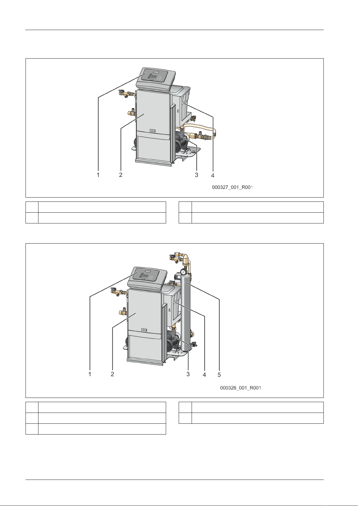
4.2.1 Fillcontrol Auto 2P...........................................................................................................................................................10
4.2.2 Fillcontrol Auto 2PS.........................................................................................................................................................10
4.3 Identification .......................................................................................................................................................................................11
4.3.1 Nameplate ........................................................................................................................................................................11
4.3.2 Type code..........................................................................................................................................................................11
4.4 Function ...............................................................................................................................................................................................12
4.4.1 Fillcontrol Auto 2P...........................................................................................................................................................12
4.4.2 Fillcontrol Auto 2PS.........................................................................................................................................................13
4.5 Scope of delivery.................................................................................................................................................................................15
4.6 Optional equipment and accessories ..............................................................................................................................................15
5Technical data ...............................................................................................................................................................................16
5.1 Electrical system..................................................................................................................................................................................16
5.2 Dimensions and connections............................................................................................................................................................16
5.3 Operation .............................................................................................................................................................................................16
6Installation.....................................................................................................................................................................................17
6.1 Installation conditions .......................................................................................................................................................................18
6.1.1 Incoming inspection .......................................................................................................................................................18
6.2 Preparatory work ................................................................................................................................................................................18
6.3 Execution..............................................................................................................................................................................................19
6.3.1 Fitting the add-on components....................................................................................................................................19
6.3.2 Floor mounting................................................................................................................................................................20
6.3.3 Hydraulic connection......................................................................................................................................................21
6.3.4 Fillcontrol Auto 2P...........................................................................................................................................................21
6.3.5 Fillcontrol Auto 2PS.........................................................................................................................................................22
6.4Electrical connection ..........................................................................................................................................................................24
6.4.1 Control cabinet terminal plan........................................................................................................................................25
6.4.2 Terminal plan, operating unit........................................................................................................................................27
6.5 Installation and commissioning certificate.....................................................................................................................................28
7Commissioning..............................................................................................................................................................................29
7.1 Requirements for initial commissioning .........................................................................................................................................29
7.2 Determining the P0minimum operating pressure for the controller.........................................................................................29
7.3 Filling the device with water.............................................................................................................................................................30

Contents
4 — English Fillcontrol Auto Make-up and degassing — 06.07.2016 - Rev. B
7.4 Modifying the controller's start routine ..........................................................................................................................................31
7.5 Parametrising the controller in the Customer menu ....................................................................................................................31
7.6 Function test........................................................................................................................................................................................32
7.6.1 Vacuum test .....................................................................................................................................................................32
7.6.2 Pump test .........................................................................................................................................................................33
7.7 Use the device to fill the facility system with water......................................................................................................................34
7.8 Starting Automatic mode..................................................................................................................................................................35
8Operation ...................................................................................................................................................................................... 36
8.1 Operating modes................................................................................................................................................................................36
8.1.1 Automatic mode..............................................................................................................................................................36
8.1.2 Manual mode...................................................................................................................................................................36
8.1.3 Stop mode ........................................................................................................................................................................37
8.1.4 Summer operation..........................................................................................................................................................38
8.1.5 Restarting .........................................................................................................................................................................38
9Controller ...................................................................................................................................................................................... 39
9.1 Operator panel ....................................................................................................................................................................................39
9.2 Configuring settings in the controller .............................................................................................................................................40
9.2.1 Customer menu...............................................................................................................................................................43
9.2.2 Service menu....................................................................................................................................................................44
9.3 Messages..............................................................................................................................................................................................45
10 Maintenance................................................................................................................................................................................. 48
10.1 Maintenance schedule.......................................................................................................................................................................49
10.2 Cleaning the dirt trap.........................................................................................................................................................................49
10.3 System degassing inspection............................................................................................................................................................50
10.4 Inspection of pressure-carrying components ................................................................................................................................50
10.5 Maintenance certificate.....................................................................................................................................................................51
11 Disassembly.................................................................................................................................................................................. 52
12 Annex ............................................................................................................................................................................................ 53
12.1 Reflex Customer Service ....................................................................................................................................................................53
12.2 Guarantee ............................................................................................................................................................................................53
12.3 Conformity and standards.................................................................................................................................................................53

Notes on the operating manual
Fillcontrol Auto Make-up and degassing — 06.07.2016 - Rev. B English —
5
1Notes on the operating manual
This operating manual is an important aid for ensuring the safe and reliable functioning of the device.
The operating manual will help you to:
• avoid any risks to personnel.
• become acquainted with the device.
• achieve optimal functioning.
• identify and rectify faults in good time.
• avoid any faults due to improper operation.
• cut down on repair costs and reduce the number of downtimes.
• improve the reliability and increase the service life of the device.
• avoid causing harm to the environment.
Reflex Winkelmann GmbH accepts no liability for any damage resulting from failure to observe the information in this operating manual.
In addition to the requirements set out in this operating manual, national statutory regulations and provisions in the country of
installation must also be complied with (concerning accident prevention, environment protection, safe and professional work practices,
etc.).
This operating manual describes the device with basic equipment and interfaces for optional equipment with additional functions. For
optional equipment and accessories, see chapter 4.6 "Optional equipment and accessories" on page 15 .
Note!
Every person installing this equipment or performing any other work at the equipment is required to carefully read this
manual prior to commencing work and to comply with its instructions. The manual is to be provided to the device operator
and must be stored near the device for access at any time.
2Liability and guarantee
The device has been built according to the state of the art and recognised safety rules. Nevertheless, its use can pose a risk to life and
limb of personnel or third persons as well as cause damage to the system or other property.
It is not permitted to make any modifications at the device, such as to the hydraulic system or the circuitry.
The manufacturer shall not be liable nor shall any warranty be honoured if the cause of any claim results from one or more of the
following causes:
• Improper use of the device.
• Unprofessional commissioning, operation, service, maintenance, repair or installation of the device.
• Failure to observe the safety information in this operating manual.
• Operation of the device with defective or improperly installed safety/protective equipment.
• Failure to perform maintenance and inspection work according to schedule.
• Use of unapproved spare parts or accessories.
Prerequisite for any warranty claims is the professional installation and commissioning of the device.
Note!
Arrange for R
eflex Customer Service to carry out commissioning and annual maintenance, see chapter 12.1 "Reflex
Customer Service
" on page 53 .

Safety
6
— English Fillcontrol Auto Make-up and degassing — 06.07.2016 - Rev. B
3Safety
3.1 Explanation of symbols
3.1.1 Symbols and notes used
The following symbols and signal words are used in this operating manual.
DANGER
Danger of death and/or serious damage to health
• The sign, in combination with the signal word 'Danger', indicates imminent danger; failure to observe the safety information will
result in death or severe (irreversible) injuries.
WARNING
Serious damage to health
• The sign, in combination with the signal word 'Warning', indicates imminent danger; failure to observe the safety information can
result in death or severe (irreversible) injuries.
CAUTION
Damage to health
• The sign, in combination with the signal word 'Caution', indicates danger; failure to observe the safety information can result in
minor (reversible) injuries.
ATTENTION
Damage to property
• The sign, in combination with the signal word 'Attention', indicates a situation where damage to the product itself or objects within
its vicinity can occur.
Note!
This symbol, in combination with the signal word 'Note', indicates useful tips and recommendations for efficient handling
of the product.

Safety
Fillcontrol Auto Make-up and degassing — 06.07.2016 - Rev. B English —
7
3.2 Personnel requirements
Only specialist personnel or specifically trained personnel may install and operate the equipment.
The electric connections and the wiring of the device must be executed by a specialist in accordance with all applicable national and
local regulations.
3.3 Personal protective equipment
When working at the system, wear the stipulated personal equipment such as hearing and eye protection, safety boots, helmet,
protective clothing, protective gloves.
See the national regulation of your country for personal protective equipment required.
3.4 Intended use
The devices must be operated only in a facility system with static pressure maintenance. The devices may be used with the following
water types:
• Non-corrosive
• Chemically non-aggressive
• Non-toxic
3.4.1 Fillcontrol Auto 2P
The device is a pressure maintaining station for heating and cooling water systems. It combines these functions:
• Adding water from a make-up system.
• System separation between facility and make-up system.
3.4.2 Fillcontrol Auto 2PS
The device is a make-up and degassing station for heating and cooling water systems. It combines these functions:
• Adding water from a make-up system.
• Degassing water from the facility system.
• System separation between facility and make-up system.

Safety
8
— English Fillcontrol Auto Make-up and degassing — 06.07.2016 - Rev. B
3.5 Inadmissible operating conditions
The device is not suitable for the following applications:
• Pressure maintaining station for the facility system.
• Mobile system operation.
• Outdoor operation.
• Usage with these media:
– Mineral oils
– Flammable fluids
• Usage with these water types:
– Distilled water
– Additive water
– Glycol-containing water
Note!
It is not permitted to make any modifications to the hydraulic system or the circuitry.
3.6 Residual risks
This device has been manufactured to the current state of the art. However, some residual risk cannot be excluded.
CAUTION
Risk of burns on hot surfaces
Hot surfaces in heating systems can cause burns to the skin.
• Wear protective gloves.
• Please place appropriate warning signs in the vicinity of the device.
CAUTION
Risk of injury due to pressurised liquid
If installation, removal or maintenance work is not carried out correctly, there is a risk of burns and other injuries at the connection
points, if pressurised hot water or hot steam suddenly escapes.
• Ensure proper installation, removal or maintenance work.
• Ensure that the system is de-pressurised before performing installation, removal or maintenance work at the connection points.
WARNING
Risk of injury due to heavy weight
The devices are heavy. Consequently, there is a risk of physical injury and accidents.
• Use suitable lifting equipment for transportation and installation.

Description of the device
Fillcontrol Auto Make-up and degassing — 06.07.2016 - Rev. B English —
9
4Description of the device
4.1 Description
The devices combine the functions makeup and degassing of water for the plant system. The system separator tank ensures the
separation of the plant system from the mains water supply.
• Fillcontrol Auto 2P.
– Makeup
– System separation
• Fillcontrol Auto 2PS.
– Makeup
– Degassing with vacuum spray pipe.
– System separation
These components regulate the device functions:
• Redundant pumps for makeup.
– The pumps draw water from the water separator tank or the vacuum spray pipe and convey it into the plant system.
• System separator tank for makeup with water.
– The system separator tank separates the makeup system from device. The float valve in the system separator tank ensures a
water supply from the makeup system.
• Controller.
– The controller regulates and monitors the functions.
• Vacuum spray pipe for degassing.
– The dissolved gases are drawn from the water via a vacuum in the spray pipe and discharged through the automatic quick
venting unit.
• Motor ball valve for feeding water into the vacuum spray pipe.
– Water from the plant system or system separator tank.
The devices are designed for these plant systems:
• Heating water systems.
• Cooling water systems.
• Solar circuits.
Note!
An initial filling of the plant system with water
is possible with the devices.

Description of the device
10
— English Fillcontrol Auto Make-up and degassing — 06.07.2016 - Rev. B
4.2 Overview
4.2.1 Fillcontrol Auto 2P
1 Operating unit 3 Pump
2 Control cabinet 4 System separator vessel
4.2.2 Fillcontrol Auto 2PS
1 Operating unit 4 System separator vessel
2 Control cabinet 5 Vacuum spray pipe
3 Pump

Description of the device
Fillcontrol Auto Make-up and degassing — 06.07.2016 - Rev. B English —
11
4.3 Identification
4.3.1 Nameplate
The nameplate provides information about the manufacturer, the year of manufacture, the manufacturing number and the technical
data.
Information on nameplate
Meaning
Type Device name
Serial No. Serial number
min. / max. allowable pressure P Minimum/maximum
permissible pressure
max. continuous operating
temperature
Maximum temperature for
continuous operation
min. / max. allowable temperature
/ flow temperature TS
Minimum / maximum
permissible temperature /
TS flow temperature
Year built Year of manufacture
min. operating pressure set up on
shop floor
Factory-set minimum
operating pressure
at site Set minimum operating
pressure
max. pressure saftey valve factory -
aline
Factory-set opening
pressure of the safety
valve
at site Set opening pressure of
the safety valve
4.3.2 Type code
No.
Designation
Type code
1 Device designation
2 Number of pumps Fillcontrol Auto 2P S
3 Degassing Yes/No 1 2 3

Des
cription of the device
12
— English Fillcontrol Auto Make-up and degassing — 06.07.2016 - Rev. B
4.4 Function
4.4.1 Fillcontrol Auto 2P
1 Operating unit 6 Pump
2 Main switch 7 Pump
3 Control cabinet 8 System connection
4 System separator vessel 9 Fresh-water system connection
5 Pressure transducer
The pressure transducer sends a signal to the controller if the pressure drops below the filling pressure of the facility system. The
controller activates the pumps. Water is added to the facility system from the system separator vessel. The float valve in the system
separator tank ensures a water supply from the make-up system.
To prevent potential dry-running, an insufficient water switch in the system separator tank will shut down the pumps, if required.
The device controller monitors the make-up with water in the facility system. These functions are monitored by the controller:
• Make-up time.
• Make-up cycles.
• Make-up quantity.
– Only if an optional contact water meter is installed
The controller interrupts the make-up when the set make-up time or the number of make-up cycles is exceeded. Small leaks in the
facility system are so detected.
The make-up quantity is controlled by the controller if an optional "FQIRA+“ water meter is installed. For the optional water meter, see
chapter 4.6 "Optional equipment and accessories" on page 15 .

Description of the device
Fillcontrol Auto Make-up and degassing — 06.07.2016 - Rev. B English —
13
4.4.2 Fillcontrol Auto 2PS
1 Vacuum gauge 10 Vacuum spray tube
2 Motor ball valve 11 Ball valve
3 Connection of degassing line with dirt trap 12 Pressure sensor
4 Automatic quick venting unit 13 Pump
5 Operating unit 14 Pump
6 Main switch 15 System connection
7 Control cabinet 16 Insufficient water switch
8 Drainage cock 17 Connection, fresh-water system with dirt trap
9 System separator vessel
The pressure transducer sends a signal to the controller if the pressure drops below the filling pressure of the plant system. The
controller activates the pumps. Water from the vacuum spray pipe is added to the plant system. The motor ball valve regulates the water
inflow into the vacuum spray pipe. Either gas-enriched water from the plant system is degassed in the vacuum spray pipe or water from
the system separator tank is added to the vacuum spray pipe. The float valve in the system separator tank ensures a water supply from
the makeup system.
To prevent potential dry-running, the integrated insufficient water protection unit in the system separator tank and the vacuum spray
pipe will shut down the pumps, if required.
The device controller monitors water degassing and makeup in the plant system. These functions are monitored by the controller:
• Makeup time
• Makeup cycles
• Makeup quantity
• Degassing
– Continuous degassing
– Interval degassing
The controller interrupts the makeup when the set makeup time or the number of makeup cycles is exceeded. Small leaks in the plant
system are detected in this way.
The makeup quantity is controlled by the controller if an optional "FQIRA+" water meter is installed. For the optional water meter, see
chapter 4.6 "Optional equipment and accessories" on page 15 .

Description of the device
14
— English Fillcontrol Auto Make-up and degassing — 06.07.2016 - Rev. B
The degassing operation in the vacuum spray pipe uses timer-controlled cycles.
1 Vacuum is drawn 4 Idling time
2 Injection PU Pump
3 Discharge
A degassing cycle comprises the following phases:
1. Vacuum is drawn.
• The pump draws a vacuum in the spray tube until the water saturation pressure is reached. For cold water, the vacuum gauge
indicates a vacuum of - 1 bar.
2. Atomisation.
• The inlet of gas-rich water to the vacuum spray pipe is opened via the motor ball valve. Gas-rich water from the plant system is
atomised in the vacuum spray pipe. The large surface of the atomised water and the gas saturation headway to the vacuum
result in a degassing of the water. The degassed water is returned from the vacuum spray tube to the plant system via the
pumps. Here it is able to dissolve gases.
3. Discharge.
• The pumps shut down. The system continues to inject and degas water in the vacuum spray tube. The water level rises. The
gases separated from the water are discharged via the degassing valve.
4. Idling time
– When the gas has been discharged, the device will remain in idle until the next cycle is started.
These degassing programmes can be selected in the controller:
• Continuous degassing.
– For continued degassing over several hours or days in a sequence of degassing cycles without idling periods. This programme
must be selected after commissioning and repairs.
• Interval degassing.
– Interval degassing comprises a limited number of degassing cycles. There is a pause time between the intervals. This
programme must be selected for continuous operation.
Note!
For setting the degassing programmes, see chapter
7.5 "Parametrising the controller in the Customer menu" on page 31 .

Description of the device
Fillcontrol Auto Make-up and degassing — 06.07.2016 - Rev. B English —
15
4.5 Scope of delivery
The scope of delivery is described in the shipping document and the content is shown on the packaging.
Proceed as follows:
1. Immediately after receipt of the goods, please check the shipment for completeness and damage.
2. Please notify us immediately of any transport damage.
Basic make-up equipment:
• The pre-wired device.
• Operating manual.
4.6 Optional equipment and accessories
The following optional equipment and accessories are available for this device:
• "FQIRA+" contact water meter.
• Softening with Reflex Fillsoft.
• Expansions for Reflex Basic controllers:
– I/O modules
– Bus modules:
• Lonworks Digital
• Lonworks
• Profibus DP
• Ethernet
Note!
Separate operating instructions are supplied with accessories.

Technical data
16
— English Fillcontrol Auto Make-up and degassing — 06.07.2016 - Rev. B
5Technical data
Note!
The following values
apply for all systems:
–
Permissible ambient temperature:
–
Degree of protection:
–
Noise level:
>0 °C – 45 °C
IP 54
55 dB
5.1 Electrical system
Type
Power output
(W)
Power supply
(V / Hz)
Fusing
(A)
Number of RS-485
interfaces
I/O module
Fillcontrol Auto 2P 500 230 / 50 10 2 Optional
Fillcontrol Auto 2PS 500 230 / 50 10 2 Optional
5.2 Dimensions and connections
Type
Weight
(kg)
Height
(mm)
Width
(mm)
Depth
(mm)
Device
connection
System
connection
Overflow
connection
Fillcontrol Auto 2P 47 930 500 560 RP ½ G 1 –
Fillcontrol Auto 2PS 55 1030 500 580 RP ½ G 1 –
5.3 Operation
Type
Make-up capacity
(l/h)
Maximum feed
pressure
(bar)
Maximum delivery
pressure
(bar)
Permissible operating
gauge pressure
(bar)
Operating
temperature
(°C)
Fillcontrol Auto 2P
≤
4200 10
≤
8.5 6 70
Fillcontrol Auto 2PS
≤
4200 10
≤
8.5 6 70

Installation
Fillcontrol Auto Make-up and degassing — 06.07.2016 - Rev. B English —
17
6Installation
DANGER
Risk of serious injury or death due to electric shock.
If live parts are touched, there is risk of life-threatening injuries.
• Ensure that the system is voltage-free before installing the device.
• Ensure that the system is secured and cannot be reactivated by other persons.
• Ensure that installation work for the electric connection of the device is carried out by an electrician, and in compliance with
electrical engineering regulations.
CAUTION
Risk of injury due to pressurised liquid
If installation, removal or maintenance work is not carried out correctly, there is a risk of burns and other injuries at the connection
points, if pressurised hot water or hot steam suddenly escapes.
• Ensure proper installation, removal or maintenance work.
• Ensure that the system is de-pressurised before performing installation, removal or maintenance work at the connection points.
CAUTION
Risk of burns on hot surfaces
Hot surfaces in heating systems can cause burns to the skin.
• Wear protective gloves.
• Please place appropriate warning signs in the vicinity of the device.
CAUTION
Risk of injury due to falls or bumps
Bruising from falls or bumps on system components during installation.
• Wear personal protective equipment (helmet, protective clothing, gloves, safety boots).
Note!
Confirm that installation and start
-up have been carried out correctly using the installation, start-up and maintenance
certificate. This action is a prerequisite for the making of warranty c
laims.
–
Have the Reflex Customer Service carry out commissioning and the annual maintenance.

Installation
18
— English Fillcontrol Auto Make-up and degassing — 06.07.2016 - Rev. B
6.1 Installation conditions
6.1.1 Incoming inspection
Prior to shipping, this device was carefully inspected and packed. Damages during transport cannot be excluded.
Proceed as follows:
1. Upon receipt of the goods, check the shipment for
• completeness and
• possible transport damage.
2. Document any damage.
3. Contact the forwarding agent to register your complaint.
6.2 Preparatory work
Preparing the device installation:
• Frost-free, well-ventilated room.
– Room temperature range: 0 °C to 45 °C.
• Filling connection.
– If necessary, provide a DN 15 filling connection according to DIN 1988 T 4.
• Electric connection: 230 V~, 50 Hz, 16 A with upstream ELCB: Tripping current 0.03 A.

Installation
Fillcontrol Auto Make-up and degassing — 06.07.2016 - Rev. B English —
19
6.3 Execution
ATTENTION
Damage due to improper installation
Additional device stresses may arise due to the connection of pipes or system equipment.
• Ensure that pipes are connected from the device to the system without stresses being induced.
• If necessary, provide support structures for the pipes or equipment.
Note!
Starting up of the pump causes vibration in the device. This transfers loud noises into the system pipes.
–
Connect the pipes to the device using flexible connections.
In systems with a diaphragm expansion tank, the device must be installed in the vicinity of the tank. To ensure that the required filling
pressure for water make-up is recorded by the pressure transducer in the device. The filling pressure depends on the minimum operating
pressure of the facility system. For calculating the minimum operating pressure,see chapter 7.2 "Determining the P0minimum operating
pressure for the controller" on page 29 .
Proceed as follows for the installation:
1. Position the device.
2. Create the water-side connections of the device to the system.
– Use connections with the same dimensions at the device for all lines.
3. If required, create the interfaces according to the terminal plan.
6.3.1 Fitting the add-on components
Install the automatic quick
-venting unit on the vacuum spray pipe.
•
Fillcontrol Auto 2PS

Installation
20
— English Fillcontrol Auto Make-up and degassing — 06.07.2016 - Rev. B
6.3.2 Floor mounting
The
device is installed on the floor. Select the attachment
means according to the floor properties.
Comply with the following instructions:
•
The device is installed sufficiently close to the
diaphragm expansion tank.
– You ensure so that the pressure sensor is able to
measure the filling pressure.
•
The fixtures can be operated.
•
Ensure sufficient space for installing the connection
lines.
Note!
The "h
st" static height is required to determine the minimum operating pressure of the plant system.
This manual suits for next models
2
Table of contents