Reflexion CarSat-65MKII TWIN User manual

Bedienungsanleitung (DEUTSCH)
Vollautomatische TWIN Satelliten-Anlage mit
65cm Spiegel
Model-Nr.: CarSat-65MKII TWIN
Lesen Sie die gesamte Anleitung des Gerätes sorgfältig durch, bevor Sie das Gerät benutzen. Bewahren Sie
die Anleitung für den weiteren Gebrauch gut auf.

2
ALLGEMEIN
Die CarSat Antennen wurden entwickelt, um auch Straßenfahrzeugen wie z.B. Wohnwagen, Minibusse,
Transporter und LKWs den vollen Komfort eines Vollautomatischen Satelliten Systems bieten zu können.
WICHTIGE SICHERHEITSHINWEISE
1. Entfernen Sie nie die Abdeckung. Es befinden sich keine Teile im Inneren, die vom Benutzer selbst
repariert werden können.
2. Das Öffnen der Abdeckungen hebt die Garantie für das Gerät auf.
3. Führen Sie Reparaturen niemals selbst durch. Für Reparaturen wenden Sie sich an den
Herstellerservice oder Ihren Fachhändler.
4. Es wird empfohlen die Montage der Satelliten Anlage an Ihrem Camping wagen oder anderen Plätzen
durch einen Fachhändler oder einer Fachwerkstatt vornehmen zu lassen. Eine nicht korrekt
ausgeführte Installation der Satelliten-Anlage kann zu Beschädigungen an der Antenne z.B. an Ihrem
Fahrzeug und zum Verlust der Garantie führen.
5. Bitte prüfen Sie stets vor dem Losfahren, dass die Antenne eingefahren ist.
6. Die Antenne immer gegen die Fahrtrichtung montieren.
7. Dieses System ist nicht geeignet für die Verwendung, während das Fahrzeug in Bewegung ist. Die
Verwendung während der Fahrt kann zu Schäden am Fahrzeug, sowie zu Sach- oder Personenschäden
führen.
8. Das Steuergerät sollte nicht in der Nähe von Hitzequellen, wie z.B. Öfen, Heizungen positioniert
werden, vermeiden Sie Hitzestau am Gerät.
9. Die Control-Box nicht an Stellen einbauen, an denen er Flüssigkeiten, Feuchtigkeit, übermäßiger Hitze
aufgrund einer fehlenden Belüftung ausgesetzt wird.
10. Wenn die Antenne mit Schnee oder Eis bedeckt ist, darf das System nicht betrieben werden. Diese Art
der Nutzung kann zu dauerhaften Schäden am System führen.
11. Beachten Sie bitte, dass sich durch die Antenne die Fahrzeughöhe entsprechend ändert, für den
ordnungsgemäßen und reibungslosen Betrieb ist der Nutzer verantwortlich.
12. Beachten Sie vor dem Montieren der Antenne, dass die Tragelast vom gewählten Montagepunkt dem
Gewicht der Antenne entspricht. Kontaktieren Sie gegeben falls Ihren Händler oder den
Fahrzeughersteller für mehr Informationen.
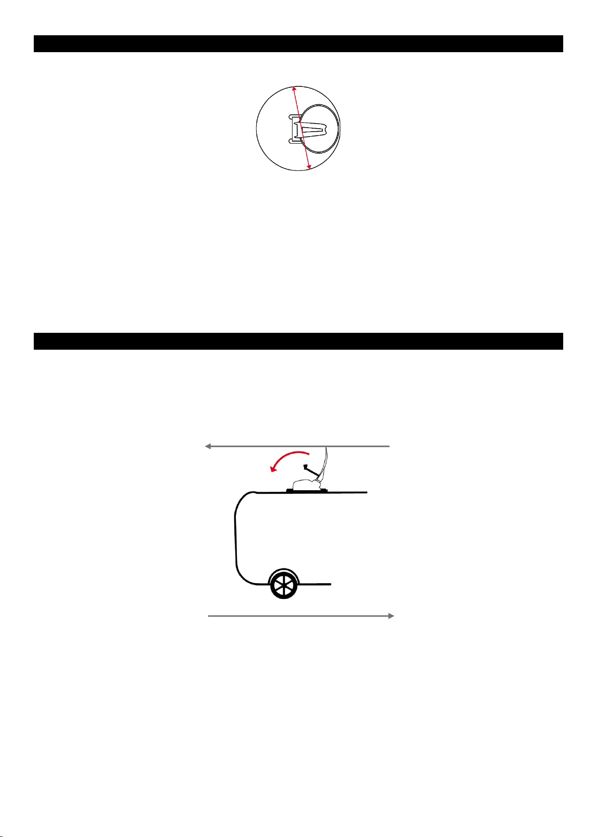
13. Bitte beachten Sie das am Montageplatz der Antenne und ca. 166cm im Querschnitt der
Rotationsbewegung bei der Satellitensuche sich keine Hindernisse befinden die zu Beschädigungen
führen können.
14. Das Fahren mit ausgefahrener Antenne ist nicht gestattet. Hierdurch können Beschädigungen am
System oder Ihrem Fahrzeug entstehen.
15. Geschwindigkeiten über 130kmh sind nicht zulässig. Es kann bei höheren Geschwindigkeiten zu
Beschädigung führen.
16. Die Satelliten Anlage ist nicht für automatische Waschstraßen geeignet.
17. Bei Gewitter trennen Sie das Steuergerät von der Satelliten Anlage.
18. Beigefügte Kabel dürfen nicht über scharfe Kanten geführt werden und nicht geknickt werden.
19. Nicht fachgerechte Gerätebezogene Handhabung führt zum Verlust der Garantie.
20. Nehmen Sie die Antenne im Ausgefahrenen Zustand nicht vom Strom, da ansonsten die Automatische
Einklapp-Funktion nicht ordnungsgemäß funktioniert.
21. Die Antenne nicht mit einer geringeren Spannung als 10,5V verwenden da es zu Funktionsstörungen
kommt.
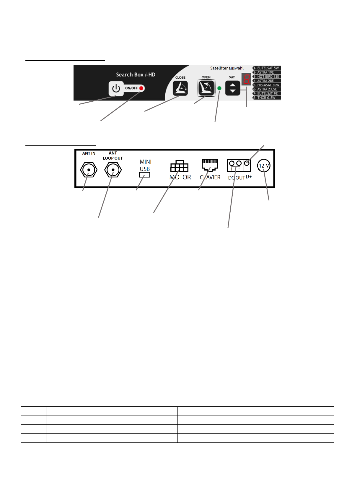
22. Verbinden Sie den Anschluss D+ von der Steuerbox mit Ihrer Fahrzeugelektronik (Zündung), um die
automatische Einklapp-Funktion zu nutzen, wenn Sie Ihr Fahrzeug starten.
23. Für die Garantieabwicklung oder bei Fragen wenden Sie sich an Ihren Fachhändler oder den
Herstellerservice.

3
LIEFERUMFANG
1. Außeneinheit (Sat-Schüssel)
2. Sat-Kabel (fest verbunden)
3. Steuerkabel (fest verbunden)
4. Kabeldurchführung (bereits mit dem Steuer-/Coaxkabel verbunden)
5. Steuer-Box
6. Zweiteilige Basis-Platte (ist an der Antenne vormontiert).
7. Installationsanleitung
Hinweis:
Kontrollieren Sie nach Erhalt des Gerätes, den Lieferumfang auf Vollständigkeit.
Das Montagematerial (z.B. Schrauben, Unterlegscheiben, Muttern, Montagekleber und
Dichtungsmasse) und Werkzeug sind nicht im Lieferumfang enthalten.
INSTALLATIONSANWEISUNG
Es wird empfohlen die Montage / Installation von einem Fachhändler oder Fachwerkstatt vornehmen
zu lassen!
ANSCHLUSSDIAGRAMM
Die folgenden Kabel werden wie in der Abbildung angeschlossen:
Stromversorgung 12V (+/-): Das rote Kabel und das schwarze Kabel werden an eine 12V 3A
Spannungsversorgung angeschlossen.
(rotes Kabel = + / schwarzes Kabel = -)
Schließen Sie die anderen Kabel gemäß der Abbildung an.
Schließen Sie die Zündung von Ihrem Fahrzeug an den Anschluss D+ der Steuer-Box an. Diese
ermöglicht das die Antenne bei Betätigung der Zündung automatisch schließt (einfährt).
Hinweis:
Fernbedienung ist optional und wird bei dieser Version nicht verwendet.
Wichtig:
Die 12V-Stromversorgung muss durch eine 10A-
Sicherung geschützt werden.
COAX-KABEL
MOTOR-KABEL
TV
HDMI
ANT IN
ANT LOOP OUT
USB
MOTOR
KEYBOARD
DC OUT
D+
D+: Die Antenne schließt sich
automatisch, sobald das
Fahrzeug gestartet wird.
SCHALTER
Ein / Aus
SICHERUNG
10A
ROT
SCHWARZ
12V
+
-
STEUER-BOX
OUT
IN
HDMI
SATELLITEN RECEIVER
12V
DC
IN

4
Der Receiver ist optional und ist nicht im Lieferumfang enthalten.
Hat Ihr TV Gerät einen DVB-S/S2 Eingang können Sie die Steuer-Box auch direkt an das TV Gerät
anschließen (ANT LOOP OUT der Steuer-Box an den DVB-S/S2 Anschluss Ihres TV Gerätes.
Bedienung
Die Steuer-Box ist für die Suche der Satelliten zuständig. Ist die Box mit einer Spannungsquelle (12V / 3A)
verbunden und eingeschaltet leuchtet die Status LED rot.
Einschalten / Ausschalten
Drücken Sie die On / Off Taste an der Steuer-Box, um die Sat-Anlage Ein- oder Auszuschalten. Ein Piep-Ton
ist beim Ein-/Ausschalten zu hören. Die Status Anzeige (Lock) blinkt beim Einschalten.
Ein: Die Status LED leuchtet rot. Die Lock LED ist aus. Die Satelliten Anzeige zeigt den ausgewählten
Satelliten an.
Aus: Die Status LED (Lock) und die Satelliten Anzeige sind aus.
Hinweis:
Wird die Steuer-Box nach dem Einschalten für ca. 2,5 Minuten nicht bedient schaltet diese
automatisch ab.
Satelliten auswählen
Wenn die „Steuer-Box“ eingeschaltet ist drücken Sie wiederholt die (SAT) Taste, um die verschiedenen
Satelliten (z.B. 2 / Astra 19E) auszuwählen bis die gewünschte (Zahl) angezeigt wird. Die folgenden Satelliten
stehen zur Auswahl:
1.
EUTELSAT 5W
5.
HISPASAT 30W
2.
ASTRA 19E
6.
ASTRA 23,5E
3.
HOT BIRD 13E
7.
EUTELSAT 9E
4.
ASTRA 28E
8.
THOR 0,8W
Hinweis:
Die „Steuer-Box“ wählt automatisch immer den zuletzt verwendeten Satelliten aus.
VORDERSEITE STEUER-BOX
RÜCKSEITE STEUER-BOX
Ein / Aus Taste
Status LED
Antenne schließen
(Einfahren)
Antenne öffnen
(ausfahren)
Zeigt ob die Antenne den
Satelliten gefunden hat
Satellitenauswahl / Anzeige des
ausgewählten Satelliten
Coaxial-Kabel
zur Antenne
Coaxial-Kabel
zum Receiver /
TV
Mini-USB Anschluss
für Updates
Motorkabel
Anschluss für
Fernbedienung
(Fernbedienung ist
optional)
Einfahr-Schutz (mit der Zündung
von Ihrem Fahrzeug verbinden)
Stromversorgung für Receiver
(Receiver ist optional)
Stromversorung
für die Steuer-Box
LOCK

5
Öffnen (ausfahren)
Drücken Sie nachdem Sie den Satelliten ausgewählt haben die (OPEN) Taste und die Antenne fährt aus.
Während die Antenne ausgerichtet wird blinkt die Status-LED und die Satelliten-Anzeige. Ist die Antenne
ausgerichtet leuchtet die LOCK-LED grün und ein doppelter Piep-Ton ertönt.
Hinweis:
Wurde die Antenne einmal ausgerichtet merkt sich die Steuer-Box die Position und beim erneuten
ausrichten wird die Position schneller gefunden. Wenn der Standpunkt der Antenne verändert
wird benötigt die Antenne wieder etwas mehr Zeit, um den Satelliten erneut zu finden.
Schließen (einfahren)
Um die Antenne zu schließen drücken Sie die (CLOSE) Taste. Während die Antenne einfährt blinkt die Status
LED und die Satelliten-Anzeige. Ist die Antenne geschlossen ertönt ein Piep-Ton und die Status LED leuchtet
rot und die Satellitenanzeige zeigt den Satelliten an.
Hinweis:
Die Antenne schließt automatisch wenn der D+ Anschluss der Steuer-Box mit der Zündung Ihres
Fahrzeugs verbunden wurde.
ACHTUNG!
Bitte kontrollieren Sie vor jedem losfahren, dass die Antenne geschlossen ist.
Längere Nichtbenutzung
Bei einer längeren Nichtbenutzung des Fahrzeugs wird empfohlen, die Stromversorgung der Steuer-Box
durch herausziehen der Sicherung zu unterbrechen.
EINFAHRSCHUTZ
Wenn die Zündung des Fahrzeugs eingeschaltet wird, fährt die Antenne automatisch in den geschlossenen
Zustand. Verbinden Sie dazu die Fahrzeugelektronik (Zündung) mit dem D+ Anschluss der Steuer-Box.
ACHTUNG!
Achten Sie stets vor jedem Losfahren das die Antenne geschlossen (eingefahren) ist bzw. dass die
Antenne bei der Betätigung der Zündung geschlossen (eingefahren) wird.
D+Auto
Die Funktion „D+ Auto“ ermöglicht ein automatisches Schließen der Antenne, ohne dass ein Kabel an die
Klemme D+ der Steuer-Box angeschlossen werden muss. Dies geschieht durch automatisches Erkennen
eines Spannungsanstiegs.
Bitte beachten Sie, dass bei aktivierter Funktion das Anschließen des Fahrzeugs an 230-V-Netz oder das
Aufladen eines Solarmoduls dazu führen kann, dass die Antenne geschlossen wird. Starten Sie in diesem Fall
einfach die Suche neu.
Es ist auch möglich, diese Funktion zu deaktivieren, gehen Sie dazu wie folgt vor:
1. Unterbrechen Sie die Spannungsversorgung der Steuer-Box.
2. Stellen Sie die Spannungsversorgung wieder und halten Sie dabei die Close Taste an der Steuer-Box
gedrückt bis eine Reihe schneller Pieptöne zu hören ist.
3. Wiederholen Sie den Vorgang, um die Funktion „D+ Auto“ wieder zu aktivieren.
Hinweis:
Während die Reihe schneller Pieptöne zu hören ist wird in der Satelliten-Anzeige der Status
angezeigt.
D+Auto Eingeschaltet: Im Display ist ein Unterstrich zu sehen.
D+Auto Ausgeschaltet: Im Display wird ein umgedrehtes A angezeigt.

6
MONTAGE / INSTALLATIONS VORBEREITUNG
Stellen Sie sicher, dass sich keine physikalischen Hindernisse am Montageort befinden, die die
Bewegung der Satellitenanlage beeinträchtigen kann. Der Drehradius der Antenne beträgt 166cm.
Erkundigen Sie sich bei Ihrem Fahrzeughersteller oder Fachhändler, ob der Ort für die Installation der
Satellitenanlage geeignet ist.
Achten Sie darauf, dass die Montagefläche eben ist.
Berücksichtigen Sie beim auswählen des Montageortes die Kabelführung ins Innere des Fahrzeugs und
das sich die Steuer-Box in der Nähe der Außeneinheit befindet.
Vergewissern Sie sich vor der Montage der Antenne das alle benötigten Materialien bereitliegen.
Vermeiden Sie unebene Montageflächen bzw. gleichen Sie diese aus.
Montieren Sie die Antenne auf dem Dach gegen die Fahrtrichtung.
Die Steuer-Box nicht an Stellen einbauen, an denen Flüssigkeiten, Feuchtigkeit, übermäßiger Hitze
aufgrund einer fehlenden Belüftung ausgesetzt wird.
MONTAGE DER AUßENEINHEIT
Nachdem Sie ein angemessener Standort für die Außeneinheit sowie der Steuer-Box gefunden haben und
Sie sich von der ausreichenden Länge der Verbindungskabel vergewissert haben folgen Sie den
Anweisungen:
1. Reinigen Sie das Dach des Fahrzeugs an der für die Montage der Außeneinheit gewählten Stelle.
2. Achten Sie darauf das die Antenne gegen die Fahrtrichtung montiert wird.
3. Verteilen Sie eine Schicht Polyurethan-Klebstoff vom Typ SIKAFLEX 252 oder einen gleichwertigen
Kleber auf den beiden Montageplatten (wie in der Abbildung markiert). Der Kleber sollte dabei
gleichmäßig und flächig aufgetragen werden.
Hinweis:
Kleber ist nicht im Lieferumfang enthalten.
166cm
Fahrtrichtung des Fahrzeugs
Schließrichtung der Antenne

7
4. Setzen Sie anschließend die Außeneinheit auf den Montageort. Der Kleber sollte sich dabei leicht
rausdrücken. Dichten Sie anschließend die Kanten mit dem Kleber ab.
5. Tragen sie überschüssigen Kleber mit einem Fugenspachtel ab.
Hinweis:
Die Montageplatten können für zusätzlichen halt auch verschraubt werden. Achtung: Dazu
müssen Löcher in das Dach Ihres Fahrzeugs gebohrt werden.
Beachten Sie die Trocknungszeiten von dem eingesetzten Kleber. Kleber nicht im Lieferumfang
enthalten.
MONTAGE DER KABELDURCHFÜHRUNG
1. Bohren Sie ein Loch in das Dach Ihres Fahrzeugs (Durchmesser: 15mm), sodass die Kabel in einem
verborgenen Bereich im Inneren des Fahrzeugs zugeführt werden.
2. Reinigen Sie den Klebebereich der Dachdurchführung.
3. Führen Sie die Kabel von außen nach innen.
4. Verteilen Sie eine große Schicht Klebstoff auf der Auflagefläche der Kabeldurchführung.
5. Pressen Sie die Kabeldurchführung gut auf das Fahrzeugdach damit der Kleber sich nach außen drückt
und die Kabeldurchführung gleichmäßig aufliegt.
6. Führen Sie rings um die Kabeldurchführung eine Klebebahn auf, um die Kabeldurchführung
abzudichten. Tragen Sie überschüssigen Kleber mit einem Fugenspachtel ab.
Hinweis:
Beachten Sie die Trocknungszeiten von dem eingesetzten Kleber. Kleber nicht im Lieferumfang
enthalten.
ELEKTRISCHE VERBINDUNG
Die Steuer-Box an ein Versorgungskabel mit einem Querschnitt von mindestens 1,5mm² mit einer
maximalen Länge von 3m anschließen. Bei größeren Längen wird ein höherer Querschnitt empfohlen.
Wichtiger Hinweis:
Wenn möglich den Anschluss der Steuer-Box an das gleiche Versorgungskabel wie das des
Fernsehers vermeiden, es sei denn das Versorgungskabel weist einen ausreichenden Querschnitt
auf.
Die Versorgung der Steuer-Box nie unterbrechen, solange die Antenne verwendet wird. Die
Funktion das die Antenne automatisch einfährt ist in diesem Fall gestört.
Beachten Sie den Spannungsbereich der Steuer-Box. Diese liegt zwischen 10,5-14V. Eine Spannung
anders als die angegebene kann zu Störungen oder einem Defekt führen.
WICHTIG:
Verbinden Sie den Kontakt (D+) auf der Rückseite der Steuer-Box mit der Zündung des Fahrzeuges
oder mit der Steuerung des Trägerfahrzeuges. Ansonsten ist die Automatische Einfahrfunktion der
Antenne nicht aktiv.

8
WARNUNG
Wir haften nicht für Unfälle oder Vorfälle, die auf eine Nichtbeachtung der Einbau- und Bedienungshinweise
zurückgehen. Das Öffnen der verschiedenen Elemente ohne unsere vorherige Genehmigung hebt jeglichen
Garantieanspruch auf. Die Sicherung mit automatischem Einzug im Fall eines Starts darf nicht verwendet
werden, um die Antenne häufig einzuziehen. Die Verwendung der gelieferten Kabel ist verpflichtend und
diese dürfen weder zugeschnitten noch verlängert werden, da sonst Funktionsstörungen eintreten können,
die nicht im Rahmen der Garantie berücksichtigt werden.
SICHERHEITSVORSCHRIFTEN
Die Antenne nicht bei Wind mit einer Geschwindigkeit von mehr als 50km/h verwenden. Die Antenne nicht
ausfahren (öffnen), wenn sie mit Schnee oder Eis bedeckt ist. Bei längeren Parken oder abstellen sollte die
Versorgung der Steuer-Box durch herausziehen der Sicherung auf der Netzzuleitung getrennt werden.
WICHTIGE BEMERKUNG
Die Antenne hat einen Drehendanschlag. Wenn der Satellit genau in der Richtung des Drehanschlags ist,
kann die Antenne nicht fokussieren und schließt. Ein langer Piep Ton wird ausgegeben, der den Fehler
anzeigt. Stellen Sie das Fahrzeug um und versuchen Sie es erneut.
Hinweis:
Weder der Verkäufer noch der Hersteller können bei Änderung des Sendebetriebs, der
Übertragungsleistung, eventuellen verschwinden von Frequenzänderung, Änderung der
Verschlüsselung sowie sonstige Änderungen der Übertragungsarten haftbar gemacht werden.
Die Empfangsbereiche der Satelliten zur Information übergeben und können von den Anbietern
geändert werden.
Änderung von Design und Spezifikation, auch ohne Vorankündigung vorbehalten.

9
TECHNISCHE DATEN
Frequenz
950 –2150Mhz
RF Ausgangsspannung
13/18V, 0/22Khz, 350mA
RF Eingang
1x F mit interner Versorgung des
LNB
Symbol Rate:
1 –45Mb/s (SCPC & MCPC) DVB-
S/S2
Signalpegel:
-65 - 25 dBm
Speisungsimpedanz des Tuners
75 Ohm
Versorgungsspannung
DC 11 - 14V
Verbrauch
1,2W im Eco-Standby-Modus,
<10W im Betrieb
Temperaturbereich
+5°C - +40°C
Features
DVB-S/S2, Einfahrschutz, 8
Voreingestellte Satelliten
Kabel (fest angeschlossen)
Sat-Kabel: 2x ca. 3m
Steuer-Box-Kabel: ca. 3m
DC Strom-Kabel: ca. 0,8m
Maße Antenne eingeklappt
(L / B / H) 83 x 57 x 17cm
Maße Steuer-Box
(L / B / H) 20 x 10,5 x 3,5 cm
Gewicht Antenne
12,3Kg
Gewicht Steuer-Box
0,58Kg
Änderung von Design und Spezifikation, auch ohne Vorankündigung vorbehalten.
ENTSORGUNGSHINWEISE
Dieses Symbol auf dem Produkt oder in der Anleitung bedeutet, dass das Gerät sowie Elektrische-
und Elektronische Geräte sowie Batterien am Ende seiner Lebensdauer getrennt von Ihrem
Hausmüll entsorgt werden müssen. Es gibt getrennte Sammelsysteme für das Recycling in der EU.
Für weitere Informationen wenden Sie sich bitte an die örtliche Behörde oder Ihren Händler, bei
dem Sie das Produkt erworben haben.
VEREINFACHTE EU-KONFORMITÄTSERKLÄRUNG
Hiermit erklärt die UltraMedia GmbH & Co. Handels KG, dass der Funkanlagentyp CarSat-65MKII TWIN der
Richtlinie 2014/53/EU entspricht.
Der vollständige Text der EU Konformitätserklärung kann unter der folgenden Internet-Adresse angefordert
werden.
https://www.ultramedia.de/produktansicht/CarSat65MKII.html
Wir wünschen Ihnen viel Freude mit dem Gerät.
Ihr UltraMedia Team

11
User manual (ENGLISH)
Fully automatic TWIN satellite system with 65cm
mirror
Model No.: CarSat-65MKII TWIN
Read the entire manual of the appliance carefully before using the appliance. Keep the instructions in a safe
place for future reference.

12
GENERAL
The CarSat antennas have been developed to provide road vehicles such as caravans, minibuses, vans and
trucks with the full convenience of a fully automatic satellite system.
IMPORTANT SAFETY INSTRUCTIONS
1. Never remove the cover. There are no parts inside that can be repaired by the user.
2. Opening the covers voids the guarantee for the appliance.
3. Never carry out repairs yourself. For repairs, contact the manufacturer's service department or your
dealer.
4. It is recommended that the installation of the satellite system in your camping vehicle or other places
be carried out by a specialist dealer or workshop. Incorrect installation of the satellite system can lead
to damage to the antenna, e.g. to your vehicle, and to the loss of the warranty.
5. Please always check that the antenna is retracted before driving off.
6. Always mount the antenna against the direction of travel.
7. This system is not suitable for use while the vehicle is in motion. Use while the vehicle is in motion
may cause damage to the vehicle, property or personal injury.
8. The control box should not be positioned near sources of heat, e.g. stoves, heaters, avoid heat build-
up on the unit.
9. Do not install the control box where it will be exposed to liquids, moisture, excessive heat due to lack
of ventilation.
10. If the antenna is covered with snow or ice, do not operate the system. This type of use may cause
permanent damage to the system.
11. Please note that the antenna changes the vehicle height accordingly, proper and smooth operation is
the user's responsibility.
12. Before mounting the antenna, make sure that the load capacity of the chosen mounting point
corresponds to the weight of the antenna. If necessary, contact your dealer or the vehicle
manufacturer for more information.
13. Please make sure that there are no obstacles at the mounting place of the antenna and approx.
166cm in the cross-section of the rotation movement during the satellite search which could lead to
damage.
14. Driving with the antenna extended is not permitted. This may cause damage to the system or your
vehicle.
15. Speeds above 130kmh are not permitted. It may cause damage at higher speeds.
16. The satellite system is not suitable for automatic car washes.
17. In the event of a thunderstorm, disconnect the control unit from the satellite system.
18. Enclosed cables must not be routed over sharp edges and must not be kinked.
19. Improper handling of the unit will invalidate the warranty.
20. Do not disconnect the antenna from the power supply when it is extended, otherwise the automatic
retraction function will not work properly.
21. Do not use the antenna with a voltage lower than 10.5V as it will cause malfunctions.
22. Connect the D+ connector from the control box to your vehicle electronics (ignition) to use the
automatic folding function when you start your vehicle.
23. For warranty processing or if you have any questions, contact your dealer or the manufacturer's
service department.
ACCESSORIES
1. Outdoor unit (satellite dish)
2. Satellite cable (permanently connected)
3. Control cable (permanently connected)
4. Roof bushing (already connected to the control/coax cable)
5. Control box
6. Two-part base plate. Is pre-mounted on the antenna.

13
7. Installation instructions
Note:
After receiving the unit, check that the scope of delivery is complete.
The assembly material (e.g. screws, washers, nuts, assembly adhesive and sealing compound) and
tools are not included in the scope of delivery.
INSTALLATION INSTRUCTIONS
It is recommended to have the assembly / installation carried out by a specialist dealer or workshop!
CONNECTION DIAGRAM
The following cables are connected as shown in the illustration:
Power supply 12V (+/-): The red cable and the black cable are connected to a 12V 3A power supply.
(red cable = + / black cable = -).
Connect the other cables according to the illustration.
Connect the ignition from your vehicle to the D+ connection of the control box. This allows the
antenna to close (retract) automatically when the ignition is activated..
Note:
Remote control is optional and not used with this version.
The receiver is optional and is not included in the scope of delivery.
If your TV set has a DVB-S/S2 input, you can also connect the control box directly to the TV set
(ANT LOOP OUT of the control box to the DVB-S/S2 connection of your TV set.
Important:
The 12V power supply must be protected by a
10A fuse.
COAX CABLE
MOTOR CABLE
TV
HDMI
ANT IN
ANT LOOP OUT
USB
MOTOR
KEYBOARD
DC OUT
D+
D+: The antenna closes
automatically as soon as the
vehicle is started.
SWITCH
ON / OFF
FUSE
10A
RED
BLACK
12V
+
-
CONTROL BOX
OUT
IN
HDMI
SATELLITE RECEIVER
12
V
DC
IN

14
Operation
The control box is responsible for searching for satellites. If the box is connected to a voltage source (12V /
3A) and switched on, the status LED lights up red.
Switch on / Switch off
Press the On / Off button on the control box to switch the satellite system on or off. A beep is heard when
switching on/off. The status indicator (Lock) flashes when the system is switched on.
On: The status LED lights up red. The Lock LED is off. The satellite display shows the selected satellite.
Off: The status LED (Lock) and the satellite display are off.
Note:
If the control box is not operated for approx. 2.5 minutes after switching on, it switches off
automatically.
Select satellites
When the "control box" is switched on, press the (SAT) key repeatedly to select the different satellites (e.g. 2
/ Astra 19E) until the desired (number) is displayed. The following satellites are available for selection:
1.
EUTELSAT 5W
5.
HISPASAT 30W
2.
ASTRA 19E
6.
ASTRA 23,5E
3.
HOT BIRD 13E
7.
EUTELSAT 9E
4.
ASTRA 28E
8.
THOR 0,8W
Note:
The "control box" always automatically selects the last satellite used.
CONNECTION DIAGRAM
Open
After selecting the satellite, press the (OPEN) button and the antenna will extend. While the antenna is
being aligned, the status LED and the satellite indicator flash. When the antenna is aligned, the LOCK LED
lights up green and a double beep sounds.
FRONT CONTROL BOX
BACK SIDE CONTROL BOX
On / Off button
Status LED
Close antenna
Open antenna
Shows if the antenna has
found the satellite
Satellite selection / display
of the selected satellite
Coaxial cable to
the antenna
Coaxial cable to
the receiver / TV
Mini-USB connection
for updates
Motor cable
Connection for remote
control is optional)
Drive-in protection (connect
to the ignition of your vehicle)
Power supply for receiver
(receiver is optional)
Power supply for
the control box
LOCK

15
Note:
Once the antenna has been aligned, the control box remembers the position and finds the
position more quickly when it is aligned again. If the position of the antenna is changed, the
antenna needs a little more time to find the satellite again.
Close
To close the antenna, press the (CLOSE) button. While the antenna is retracting, the status LED and the
satellite indicator flash. When the antenna is closed, a beep sounds and the status LED lights up red and the
satellite indicator shows the satellite.
Note:
The antenna closes automatically when the D+ connection of the control box is connected to the
ignition of your vehicle.
ATTENTION!
Please check that the antenna is closed each time before driving off.
Prolonged non-use
If the vehicle is not going to be used for a long period of time, it is recommended to disconnect the power
supply to the control box by pulling out the fuse.
ROLL-IN PROTECTION
When the vehicle's ignition is switched on, the antenna automatically moves into the closed state. To do
this, connect the vehicle electronics (ignition) to the D+ connection of the control box.
ATTENTION!
Always ensure that the antenna is closed (retracted) before driving off or that the antenna is
closed (retracted) when operating the ignition.
D+Auto
The function "D+ Auto" enables automatic closing of the antenna without having to connect a cable to the
D+ terminal of the control box. This is done by automatically detecting a voltage rise.
Please note that when this function is activated, connecting the vehicle to 230 V mains or charging a solar
module can cause the antenna to close. In this case, simply restart the search.
It is also possible to deactivate this function, proceed as follows:
1. Disconnect the power supply to the control box.
2. Restore the power supply while pressing and holding the Close button on the control box until you
hear a series of fast beeps.
3. Repeat the procedure to reactivate the "D+ Auto" function.
Note:
While the series of fast beeps is heard, the satellite display shows the status.
D+Auto Switched on: An underscore is shown in the display.
D+Auto Switched off: An inverted A is shown in the display.
ASSEMBLY / INSTALLATION PREPARATION
Make sure that there are no physical obstacles at the mounting location that may interfere with the
movement of the satellite system. The turning radius is 166cm.
166cm

16
Check with your vehicle manufacturer or specialist dealer whether the location is suitable for installing
the satellite system.
Make sure that the mounting surface is level.
When selecting the installation location, take into account the cable routing inside the vehicle and that
the control box is located near the external unit.
Before mounting the antenna, make sure that all the necessary materials are available.
Avoid uneven mounting surfaces or level them out.
Mount the antenna on the roof against the direction of travel.
ASSEMBLY OF THE EXTERIOR UNIT
Do not install the control box where it will be exposed to liquids, moisture, excessive heat due to lack
of ventilation.
After you have found a suitable location for the outdoor unit and the control box and have made sure that
the connecting cables are long enough, follow the instructions.of the connection cables, follow the
instructions:
1. Clean the roof of the vehicle at the location chosen for mounting the outdoor unit.
2. Make sure that the antenna is mounted against the direction of travel.
3. Spread a layer of SIKAFLEX 252 polyurethane adhesive or an equivalent adhesive on the two mounting
plates (marked red). The adhesive should be applied evenly and over a wide area.
4. Then place the outdoor unit on the installation site. The adhesive should press out slightly. Then seal
the edges with the adhesive.
5. Remove excess adhesive with a joint spatula.
Note:
The mounting plates can also be screwed in place for additional support. Caution: Holes must be
drilled in the roof of your vehicle for this purpose.
Please note the drying times of the adhesive used. Adhesive is not included in the scope of
delivery.
Direction of travel of the vehicle
Closing direction

17
MOUNTING THE CABLE GLAND
1. Drill a hole in the roof of your vehicle (diameter: 15mm) so that the cables are fed into a hidden area
inside the vehicle.
2. Clean the adhesive area of the roof grommet.
3. Feed the cables from the outside to the inside.
4. Spread a large layer of adhesive on the contact surface of the cable grommet.
5. Press the cable entry well onto the vehicle roof so that the adhesive presses outwards and the cable
entry lies evenly.
6. Apply a strip of adhesive around the cable gland to seal the cable gland. Remove excess adhesive with
a joint filler.
Note:
Observe the drying times of the adhesive used. Adhesive not included in the scope of delivery.
ELECTRICAL CONNECTION
Connect the control box to a supply cable with a cross-section of at least 1.5mm² with a maximum length of
3m. For longer lengths, a higher cross-section is recommended.
Important notice:
If possible, avoid connecting the control box to the same power cable as the TV, unless the power
cable has a sufficient cross-section.
Never interrupt the power supply to the control box while the antenna is in use. The function of
the antenna to retract automatically is disturbed in this case.
Observe the voltage range of the control box. This is between 10.5-14V. A voltage other than that
specified can lead to malfunctions or a defect.
IMPORTANT:
Connect the contact (D+) on the back of the control box to the ignition of the vehicle or to the
control of the carrier vehicle. Otherwise the automatic retraction function of the antenna is not
active.
WARNING
We are not liable for accidents or incidents resulting from failure to observe the installation and operating
instructions. Opening the various elements without our prior authorisation will invalidate any warranty
claim. The fuse with automatic retraction in the event of a start must not be used to retract the antenna
frequently. The use of the supplied cables is obligatory and they must not be cut or extended, otherwise
malfunctions may occur which are not covered by the warranty.
SAFETY REGULATIONS
Do not use the antenna in wind with a speed of more than 50km/h. Do not extend (open) the antenna if it is
covered with snow or ice. When parked or parked for a longer period of time, the power supply to the
control box should be disconnected by pulling out the fuse on the power supply line.
IMPORTANT REMARK
The antenna has a rotating stop. If the satellite is exactly in the direction of the rotation stop, the antenna
cannot focus and closes. A long beep is emitted indicating the error. Move the vehicle and try again.
Note:
Neither the seller nor the manufacturer can be held liable in the event of a change in transmission
operation, transmission power, possible disappearance of frequency change, change in encryption
as well as other changes in transmission modes.
The reception ranges of the satellites are provided for information and may be changed by the
providers.

18
Design and specification subject to change without notice.
TECHNICAL DATA
Frequency
950 –2150Mhz
RF output voltage
13/18V, 0/22Khz, 350mA
RF input
1x F with internal supply of the
LNB.
Symbol Rate:
1 –45Mb/s (SCPC & MCPC) DVB-
S/S2
Signal level:
-65 - 25 dBm
Supply impedance of the tuner
75 Ohm
Supply voltage
DC 11 - 14V
Power consumption
1,2W in eco standby mode, <10W
in operation
Temperature range
+5°C - +40°C
Features
DVB-S/S2, drive in protection, 8
Preset satellites
Cable (permanently connected)
Sat cable: 2x approx. 3m
Control box cable: approx. 3m
DC power cable: approx. 0,8m
Dimensions antenna folded
(L / B / H) 83 x 57 x 17cm
Dimensions control box
(L / B / H) 20 x 10,5 x 3,5 cm
Weight antenna
12,3Kg
Weight control box
0,58Kg
Design and specification subject to change without notice.

19
DISPOSAL INSTRUCTIONS
This symbol on the product or in the instructions means that the appliance, electrical and electronic
equipment and batteries must be disposed of separately from your household waste at the end of
their working life. There are separate collection systems for recycling in the EU. For more
information, please contact the local authority or your dealer where you purchased the product.
SIMPLIFIED EU DECLARATION OF CONFORMITY
UltraMedia GmbH & Co. Handels KG hereby declares that the radio equipment type CarSat-65MKII TWIN is
in compliance with Directive 2014/53/EU.
The full text of the EU Declaration of Conformity can be requested at the following internet address.
https://www.ultramedia.de/produktansicht/CarSat65MKII.html
We hope you enjoy using the device.
Your UltraMedia Team
WARRANTY
CarSat-65MKII TWIN
Table of contents
Languages:
Other Reflexion Antenna manuals
Popular Antenna manuals by other brands

AntennaCraft
AntennaCraft C290 installation instructions

Sea Tel
Sea Tel 5012-91 installation manual

AR
AR ATH Series Operating and service manual

Ericsson
Ericsson AIR 21 Mount instructions

Williams Sound
Williams Sound ANT 024 Setup instructions

Directive Systems & Engineering
Directive Systems & Engineering DSE2324LYRM quick start guide