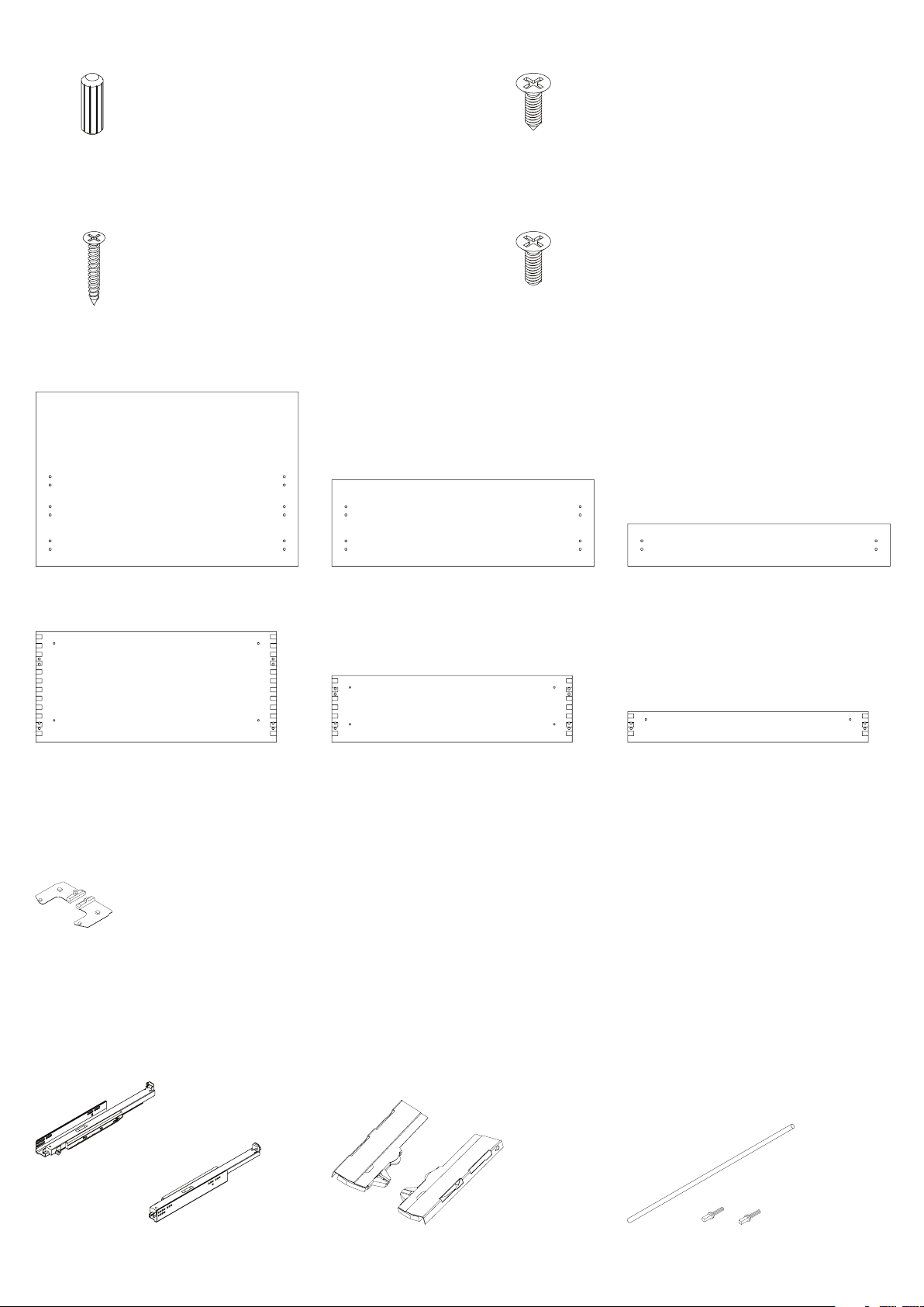
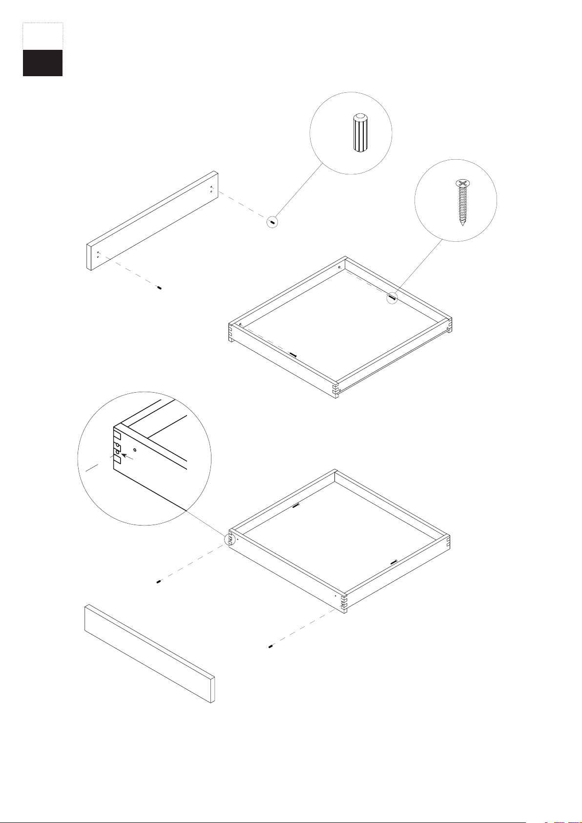
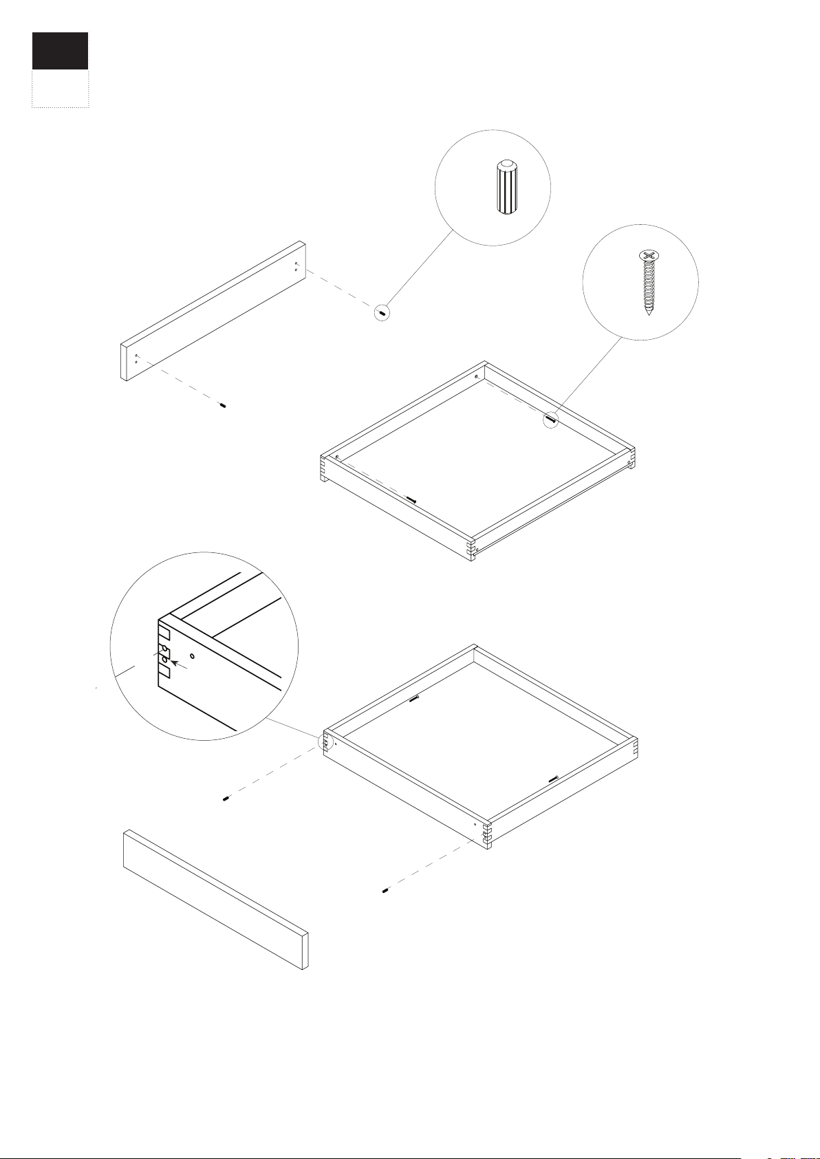
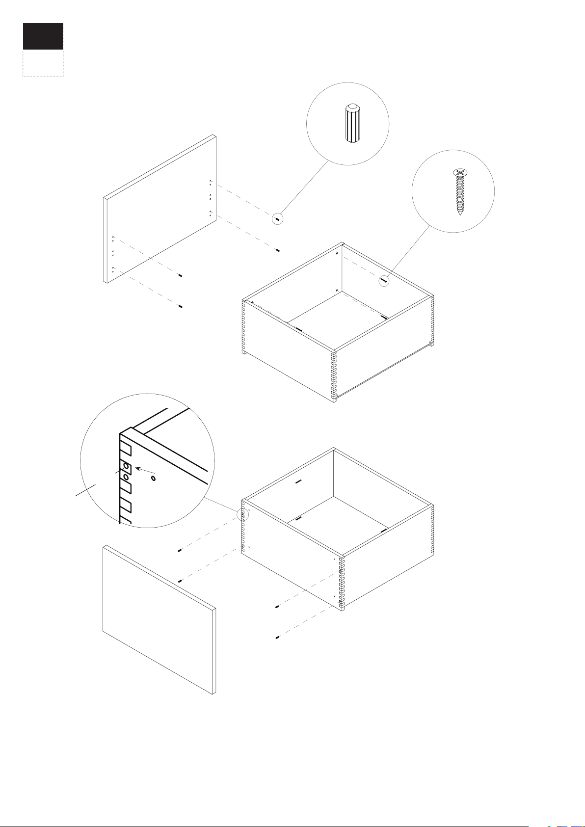
Reform WOOD DRAWERS User manual

WOOD DRAWERS
Installation Guide

2
WOODEN DOWEL
D 5 mm x L 15 mm
To mount the fronts
LARGE SCREW
M 4 mm x L 25 mm
To mount the fronts
WOOD SCREW
M 6 mm x L 13 mm
To mount the drawer slides to the cabinets
SMALL SCREW
M 6 mm x L 13 mm
To mount the drawer slides to the cabinets
High front 40 cm
High drawer 23,5 cm
Medium front 20 cm
Medium drawer 13,5 cm
Low front 10 cm
Low drawer 5,5 cm
Synchronization rod for TIP-ON / BLUMOTIONUnit for TIP-ON / BLUMOTION
Left and right parts
Drawer slides
Length 32 cm or 50 cm
Locking device for TIP-ON / BLUMOTION
Left and right part

3
Reform’s wooden drawers are delivered assembled. The only thing you should do is to
install the drawer slides to the inside of the cabinet and click the drawers onto the slides.
All ’medium’ and ’high’ drawers have four holes for dowels on each side of the front
drawers and the two holes for screws on each side.
The ’low’ drawers only have one pair of holes for dowels on each side.
All fronts – except the bottom drawer of the cabinet – must be mounted to the drawer
with a dowel in the top hole of each pair of holes.
INSTALLING THE DRAWER FRONTS
’LOW’ DRAWER
When mounting the lower drawer
’MEDIUM’ DRAWER
When mounting the lower drawer
’HIGH’ DRAWER
When mounting the lower drawer
NB
Be aware that the lower drawer of the cabinet
is mounted to the drawer dierently from the
remaining drawers.

4
’LOW’ DRAWER
Front
Back
Step 1
Step 2
2x
2x
All drawers placed at the bottom of the cabinet must be mounted with dowels in the
bottom two holes in the drawers, but should be mounted in the top holes on the fronts.
This is to ensure that the front covers the bottom of the cabinet. Then the drawer and
front are secured with screws in the holes from the inside of the drawer.

5
The middle drawer or the top drawer. The drawer and front are assembled with dowels
in the top holes on each side of the drawer. Then the drawer and front are secured with
screws.
Front
Back
Step 1
Step 2
2x
2x

6
Front
Back
Step 1
Step 2
4x
4x
All drawers placed at the bottom of the cabinet must be mounted with dowels in the
bottom two holes in the drawers, but should be mounted in the top holes on the fronts.
This is to ensure that the front covers the bottom of the cabinet. Then the drawer and
front are secured with screws in the holes from the inside of the drawer.
’MEDIUM’ DRAWER

7
Front
Back
Step 1
Step 2
4x
4x
The middle drawer or the top drawer. The drawer and front are assembled with dowels in
the top two holes on each side of the drawer. Then the drawer and front are secured with
screws in the holes from the drawer.

8
Front
Back
Step 1
Step 2
4x
4x
All drawers placed at the bottom of the cabinet must be mounted with dowels in the
bottom two holes in the drawers, but should be mounted in the top holes on the fronts.
This is to ensure that the fronts cover the bottom of the cabinet. Then the drawer and
front are secured with screws in the holes from the inside of the drawer.
’HIGH’ DRAWER

9
Front
Back
Step 1
Step 2
4x
4x
The middle drawer or the top drawer. Drawer and front are first assembled with dowels in
the top holes on each side of the drawer. Then the drawer and front are assembled with
screws in the holes from the drawer.

10
DRAWERS AND DRAWER SLIDES
NB
If you have chosen a design with no handles
and ordered TIP / ON BLUMOTION for push
open functionality, refer to page 14 for detailed
assembly instructions BEFORE you install the
drawer slides.
Reform’s wood drawers are delivered together with the drawer slides. Install the drawer
slides on the cabinet and then click the drawer on the slides. Refer to the guide on page
13 on how to get the drawer on the slides. The slides are marked with R for the right side
and L for the left side.
The lower drawer slides are mounted dierently than the other slides. The lower drawer
slides are mounted in the lower row of holes, while the rest of the slides are mounted in
the upper row of holes of the slide.

11
15
14
13
12
11
10
9
8
7
6
5
4
3
2
1
15
14
13
12
11
10
9
8
7
6
5
4
3
2
1
15
14
13
12
11
10
9
8
7
6
5
4
3
2
1
15
14
13
12
11
10
9
8
7
6
5
4
3
2
1
15
14
13
12
11
10
9
8
7
6
5
4
3
2
1
15
14
13
12
11
10
9
8
7
6
5
4
3
2
1

12
MOUNTING OF DRAWER SLIDES
All bottom drawer slides: Must be mounted in the lower row of holes with small flat tip
screws.
Counted from the front: 4+5 hole. The other drawer slides are fitted with flat tip screws.
Counted from the front: 4+10. The holes for the screws are pre-drilled. All drawer slides
must be mounted with a wood screw in the rearmost and last hole. This hole is not pre-
drilled.
2x4x

13
Step 1
Step 2
MOUNTING OF DRAWERS ON DRAWER SLIDES
Mount the wooden drawer by placing the drawer on the drawer slides and push it back to
the bottom of the slides. Be aware that the two holes on the back of the drawer must be
connected with the small tap at the back of the slides.

14
TIP ON BLUE MOTION
TIP-ON / BLUMOTION is used for the designs with no handle. The TIP-ON / BLUMOTION
system for the drawer slides is installed before attaching the drawer slides to the cabinet.
After the TIP-ON / BLUMOTION is mounted to the drawer slides you can install the slides
to the cabinet and then mount the synchronization rod. The drawer is now ready to be
installed.
The items are marked with R for right and L for left. All right parts fit together and all left
parts fit together. Regarding the TIP-ON / BLUMOTION it’s important that the drawers
are properly adjusted in relation to the cabinet. See page 20 for adjustment instructions.

15
1
1
2
2
INSTALLING THE LOCKING DEVICE TO THE TIPON
BLUMOTION
The lock for the TIP-ON system is installed on the underside of the drawer slide as
illustrated by the arrows on the locks.
First, push the red-marked part firmly onto the drawer slide then rotate the lock firmly as
illustrated by arrow 2.

16
1
1
2
2
INSTALLING THE LOCK PART TO THE TIPON
BLUMOTION
Slide the lock part into the hole on the backside of the drawer slide. Then turn it 90
degrees into the lock position, as illustrated.

17
1
2
INSTALLING THE UNIT TO THE TIPON BLUMOTION
The TIP-ON / BLUMOTION unit is connected to the drawer slide by attaching it to the
two tabs on the drawer slide as illustrated. Then pull the unit in the direction as shown by
the arrow 2.

18
1
2
1
INSTALLING THE UNIT TO THE TIPON BLUMOTION
Please note that the unit must be clicked firmly to the drawer slide. The device is
mounted correctly when arrow 1 on the unit is clicked all the way down to the icon with
the lock symbol.

19
INSTALLING THE SYNCHRONIZATION ROD TO THE TIPON
BLUMOTION
When the lock and the unit are mounted on the drawer slides, the drawer slides are ready
to be mounted to the cabinet. Attach the synchronization rod between the two slides.
The synchronization rod provides a more stable opening and closing process.
NB
Refer to page 10 for mounting drawer slides.
Please note that the lower drawer slides are
mounted dierently than the remaining drawer
slides.

20
+2
min. 3 mm
-1
It’s important to fine-tune the distance between the drawers and the cabinet after they
have been installed to make sure that the TIP-ON / BLUMOTION system work optimally.
Measure approximately. 3 mm between the backside of the drawer fronts and the cabinet
to allow the push open functionality to work properly. To fine-tune each of the units, turn
the wheel as illustrated.
TIPON BLUMOTION FINAL ADJUSTMENT
Popular LCD Drawer manuals by other brands

Neuro Logic Systems
Neuro Logic Systems NLS 1U Server Console RFT-17 installation guide

BLUM
BLUM TANDEM plus BLUMOTION 563.4570B instructions

Synergy Global Technology
Synergy Global Technology LCD1U17-013 user manual

KVMSwitchTech
KVMSwitchTech RKD-KVM-19 Series user manual

Mocka
Mocka Maya Three Drawer Assembly instructions

Miele
Miele ABLG 202 installation instructions

Rose electronics
Rose electronics KVM Rack Drawer Installation and operation manual

Aurora
Aurora 144/2870 Assembly instructions

Austin Hughes Electronics
Austin Hughes Electronics CyberView W-119 series user manual

CyberView
CyberView N117 Series user manual

I-Tech
I-Tech HRKP115 Specifications

I-Tech
I-Tech RKP1015-1601 user manual