Rega DAC Wolfson WM8742 User manual

CON EN S
NTRODUCT ON 1
TECHNOLOGY 2
FRONT PANEL ND CATORS & CONTROLS 3
BACK PANEL 4
N USE & D G TAL OUTPUT 5
F LTER SETT NGS 6
CONNECT V TY 7
USB CONNECT V TY 8
96kHz-192kHz OPERAT ON 9
TECHN CAL SPEC F CAT ONS 10
TROUBLESHOOT NG 11
TROUBLESHOOT NG 12
GLOSSARY OF TERMS 13

2
ECHNOLOGY
The input stage comprises a Wolfson digital receiver with a high stability low
jitter clock driving the receiver PLL. The receiver and PLL have their own
dedicated power supplies. The DAC stage comprises of a pair of parallel-
connected Wolfson WM8742 DAC’s, which are driven via a buffer stage, which
ensures the integrity of the data being fed to the DAC C’s – similar to the
arrangement used in the sis (Rega’s reference CD player).
The output amplifier employs a discrete differential multiple feedback filter and
output amplifier, with a high cut-off frequency for use with higher sample rates.
We decided not to use a sample rate converter and process the data at the
incoming sample rate which keeps the signal processing to a minimum. Jitter
was minimised by synchronously clocking the digital data with our receiver PLL
(removing any jitter from the input signal).
All the capacitors associated with the analogue signal path are Nichicon FG
bypassed with MMK polyester capacitors, and low impedance conductive
polymer capacitors are used for DAC decoupling. The power supply utilizes a
toroidal transformer, fast rectifier diodes and again Nichicon FG capacitors.
There is a power supply for the control microcontroller, separate from the
digital & analogue audio stages. Special attention being paid to the inter C
control signals ensuring the control data noise is kept to a minimum.
IN RODUC ION
The Rega DAC is a 16/20/24-bit at 32kHz to 192kHz digital to analogue
converter incorporating an enhanced version of the Rega designed circuit.
Developed to be simple to set up and use, the Rega DAC is designed to optimise
performance from any two channel PCM digital audio source.
With the PC (although a somewhat contentious issue in hi-fi circles) now widely
accepted as a creditable medium for storing and streaming music. The use of
high quality lossless files such as WAV, FLAC and ALAC offer performance
through the DAC equal to and in some cases better than red book CD. Great
care has been taken to remove noise generated by the PC and other input
sources. During development this was identified as a major drawback with
many DAC’s on the market today.
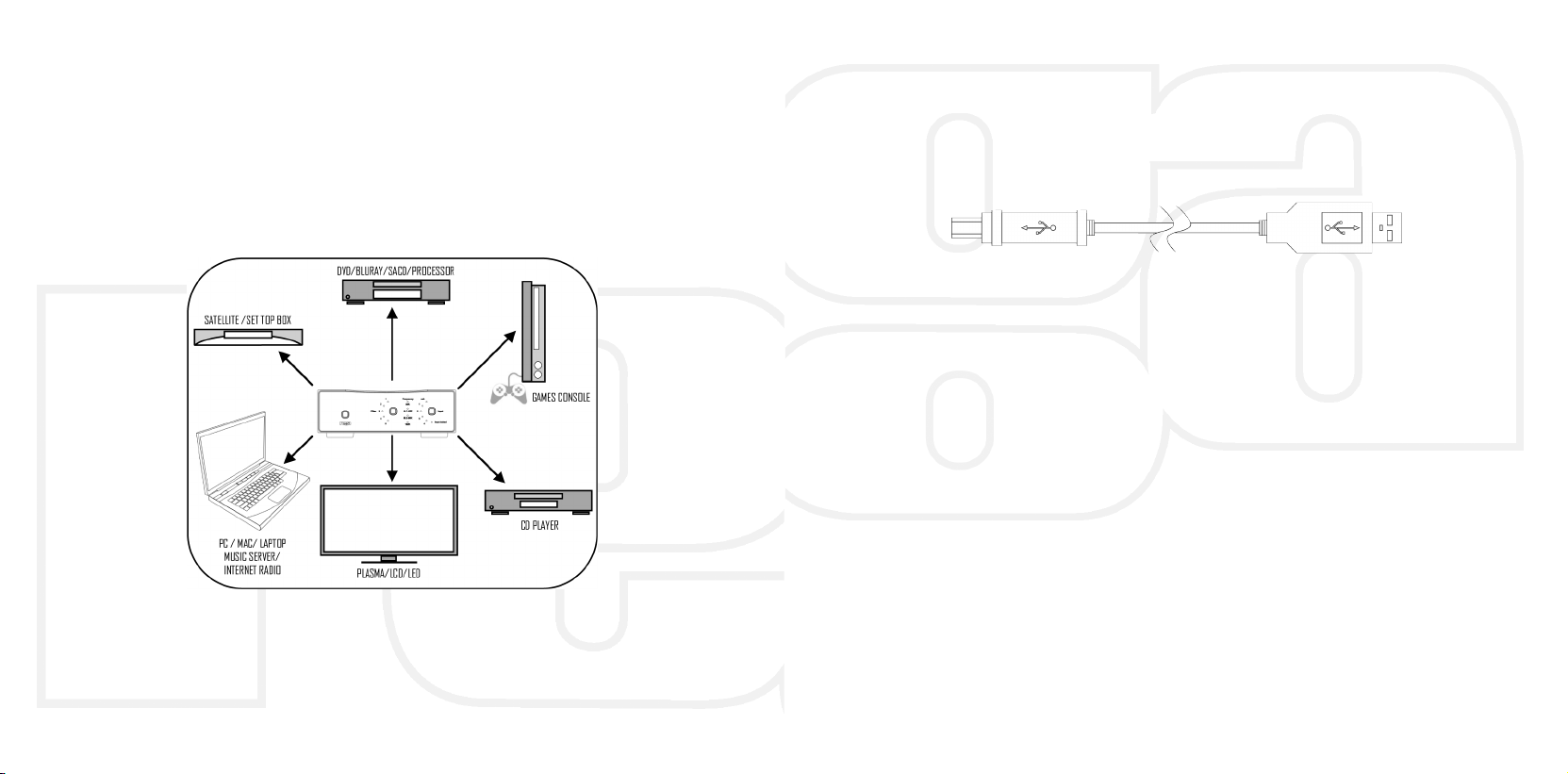
The Rega DAC housed in a custom aluminium and steel case boasts a pair of
Wolfson DAC C’s and 5 user selectable digital filters, two isolated Co-axial
inputs, two Toslink SPD F inputs and an isolated USB input.
The Rega DAC has been designed and engineered to achieve the highest
performance in its class. We hope you enjoy this Rega product for many years
to come.
1

BACK PANEL
Digital Inputs
USB - type B connector/ solated
Optical Digital Input 1 - Optical/Toslink
Optical Digital Input 2 - Optical /Toslink
Co-Ax Digital Input 3 - solated 75Ω Co-axial Phono
Co-Ax Digital Input 4 - solated 75Ω Co-axial Phono
Digital output (via receiver & PLL) -SPD F
Optical Toslink
Co-axial/Phono solated 75Ω
Analogue Output Left and Right Phono
Power Mains/line input EC C5 type
Fuse Fuse holder
3
FRON PANEL INDICA ORS AND CON ROLS
Power on/off (button above Rega logo) When the power button is pressed
the Rega logo illuminates to indicate power is on.
Input Locked indicator This indicates the digital input signal is valid and the
PLL in the receiver is locked. When the nput Locked LED is off the soft mute is
activated.
Input This button selects the 5 available digital inputs. Push to advance to the
next input as follows:
USB Optical 1 Optical 2 Co-axial 3 Co-axial 4
Sample rate LED’s (only valid when nput Locked is on)
32K – ndicates the incoming sample rate is 32kHz
44.1/48K – ndicates the incoming sample rate is 44.1 or 48kHz
88.2/96K – ndicates the incoming sample rate is 88.2 or 96kHz
192K – ndicates the incoming sample rate is 176.4 or 192kHz
4

5
FIL ER SE INGS
The cut-off points of the filters are in the upper end of the frequency range.
However, due to complex technical phenomena, this will have an effect lower in
the frequency band. For further description see the glossary of terms. These
settings are a matter of personal taste and may only offer subtle changes. We
suggest using Filter setting 1 and trying different settings with various
equipment.
Filter setting switch & LED’s Push to advance to the next filter.
Filter settings 1 – 5
(low sample rates 32/44.1/48K)
1 Linear phase half-band filter
2 Minimum phase soft-knee filter
3 Minimum phase half-band filter
4 Linear phase apodising filter
5 Minimum phase apodising filter
Filter settings 1 – 5
(medium & high sample rates 88.2/96 & 176.4/192K)
1 Linear phase soft-knee filter
2 Minimum phase soft-knee filter
3 Linear phase brickwall filter
4 Minimum phase apodising filter
5 Linear phase apodising filter
IN USE
Power-up the DAC using the power switch on the front panel. After a few
seconds you will hear an audible click from the output mute relay and the
analogue audio will be active. Please note: The front panel will display the
previously selected setting’s displayed before the unit was last powered down.
f the currently selected input has an active source connected the Input Locked
LED along with the appropriate incoming sample rate LED will illuminate. Unless
the Input Locked LED is lit the sample rate indication is irrelevant. By pressing
the input selection switch you can select any one of the inputs. When the Input
Locked LED is off, or there is a transmission error the internal soft mute is
activated automatically.
By pressing the Filter selection switch you can select any one of the 5 available
digital filters 1,2,3,4 or 5. (The exact properties of these filters are outlined on
the opposite page).
DIGI AL OU PU
The digital output mirrors the selected input. For example when input 2 has
been selected the digital output will be the signal present on input 2 but cleaned
up and re-clocked, this can be used to drive an auxiliary piece of equipment if
so desired.
6

7
USB CONNEC IVI Y
Connect a USB A-B type lead (as illustrated) from the DAC USB to a USB output
on your PC. The standard Windows ‘
found new hardware
’ dialogue will be
displayed on your PC in the bottom right hand corner of the screen.
USB A-B lead (not supplied)
The DAC will be recognised as ‘USB AUD O DAC’. nstallation should be
automatic as no driver disc is required. After a short period
‘your new
hardware is installed and ready to use’
should appear to confirm that
connection and installation has been successful.
t is recommended to switch off any other system sounds emitted by the PC via
the control panel. The DAC will automatically become the default for your PC
whilst connected. Once disconnected the previous default will be restored. f
this does not happen you can manually reset as follows :
Windows XP
- Control panel/Sounds and audio devices/Audio/Sound Playback
Windows Vista/Windows 7
- Control Panel/Hardware and Sound/Manage Audio
Devices/select ‘USB AUD O DAC’ from list.
Mac OS
- System Preferences/Sound Output/Select Audio USB DAC.
CONNEC IVI Y (examples)
1 USB A-B/ 2 OP ICAL/3 CO-AXIAL
This page offers ‘suggested connectivity’, with so many products offering a
number of options it is important to check the manual of the product your are
connecting, for the appropriate or optimum output connection and settings
required to operate properly.
Note: This unit only accepts two-channel PCM digital audio. You cannot connect
a Dolby Digital 5.1/7.1 or a DTS signal as they will not be recognised. f you wish
to connect a DVD or similar device, please ensure that the sound output of your
player is set to two-channel PCM.
8
Table of contents
Other Rega Media Converter manuals
Popular Media Converter manuals by other brands

H&B
H&B TX-100 Installation and instruction manual

Bolin Technology
Bolin Technology D Series user manual

IFM Electronic
IFM Electronic Efector 400 RN30 Series Device manual

GRASS VALLEY
GRASS VALLEY KUDOSPRO ULC2000 user manual

Linear Technology
Linear Technology DC1523A Demo Manual

Lika
Lika ROTAPULS I28 Series quick start guide

Weidmuller
Weidmuller IE-MC-VL Series Hardware installation guide

Optical Systems Design
Optical Systems Design OSD2139 Series Operator's manual

Tema Telecomunicazioni
Tema Telecomunicazioni AD615/S product manual

KTI Networks
KTI Networks KGC-352 Series installation guide

Gira
Gira 0588 Series operating instructions

Lika
Lika SFA-5000-FD user guide