Regal Century V-Green 2517369-001-001-0A Guide

A Regal Brand
V-Green Automaon Adapter Kit
Installaon Manual and User’s Guide
For use with Century® V-Green Variable Speed Motors

COPYRIGHT
Copyright 2013, Regal Beloit America, Inc., Tipp City, Ohio. All rights reserved.
TRADEMARKS
All trademarks and registered trademarks® are the property of their respecve
companies. The informaon in this document incorporates proprietary rights
and is not to be duplicated wholly or in part without the express wrien
permission of Regal Beloit Corporaon and / or Regal Beloit America, Inc.
April 2013/USA

1
Contents
Kit Contents ....................................................................................3
Introducon ....................................................................................4
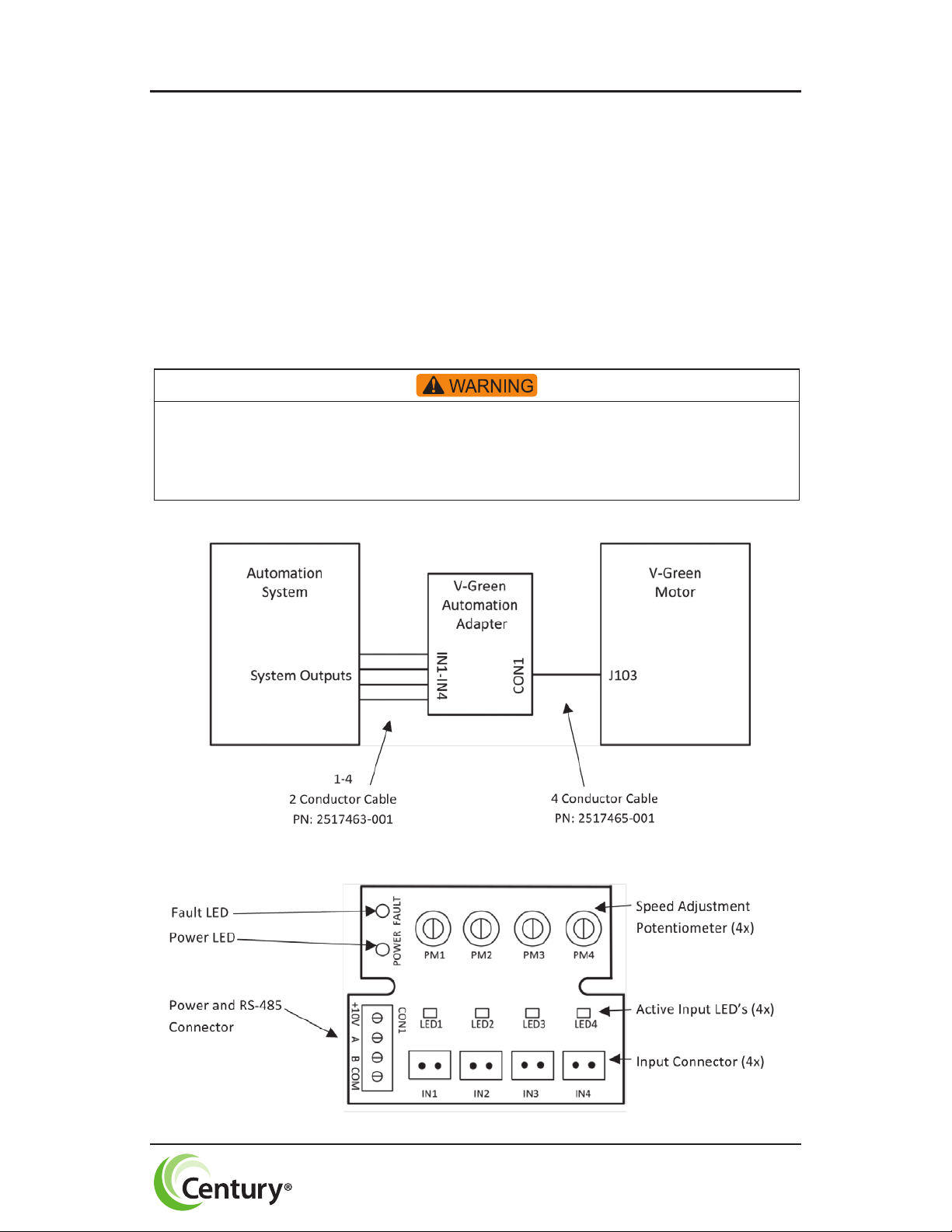
Overview .....................................................................................4
Connecng to a V-Green motor .....................................................6
Connecng to an alternate power source ....................................13
Connecng to an automaon system...........................................14
- Using automaon system output connectors ......................14
- Using automaon system relays ...........................................15
˃ Connecng to Input side of Relays ................................15
˃ Connecng to Output side of Relays .............................16
- Output Signal Powered by Automaon Adapter ......16
- Output Signal Powered by Alternate Power Supply .17
Operang a V-Green Automaon Adapter ...................................18
Adjusng Motor Speed ........................................................... 18
FAULT Status .................................................................................19
Troubleshoong Guide .................................................................19
Specicaons ................................................................................20

DANGER
NOTICE
2
SAFETY
Safety is emphasized throughout this user manual. These are safety alert sym-
bols and signal words. They alert the user to potenal personal injury hazards.
Obey all safety messages to avoid possible injury or death or damage to equip-
ment and other property.
DANGER
DANGER indicates a hazardous situaon which, if not avoided, will result in
death or serious injury.
WARNING
WARNING indicates a hazardous situaon which, if not avoided, could result in
death or serious injury.
CAUTION
CAUTION indicates a hazardous situaon which, if not avoided, could result in
minor or moderate injury.
NOTICE
NOTICE idenes potenal equipment damage or failure condions. Also, alerts
personnel to potenally dangerous situaons.

PART PART NUMBER QTY
Automaon
Adapter 2517369-001 1
Digital Input Cable 2517463-001 4
Lead Cable 2517465-001 25 FT
RS-485 Connecor 2511130-001 1
Conduit Fing 2017587-002 1
Terminal Box Cover
Assembly 1
Plug 2514059-001 4
Screw Driver 2517831-001 1
3
KIT CONTENTS
2513409-001 (Grey)
2513409-002 (Black)

INTRODUCTION
The V-Green Automaon Adapter provides the ability to operate a V-Green
motor with a 3rd party automaon system such as the Hayward Goldline Pro
Logic, Pentair Easytouch, Jandy Aqualink, and Intermac controls. This will
allow the user to control and experience the full variable speed capability of a
V-Green product through an exisng automaon system.
OVERVIEW
System:
Adapter Control Board:
Figure 2
Figure 1
4
Access to the connections referenced in the diagrams below could be in close proximity
to mains connections which carry line voltage capable of causing personal injury or
damaging the equipment if contact is made. Power should be turned off when accessing
these areas.

Power/ RS-485 Input
CON1:
Digital Inputs:
IN1, IN2, IN3, IN4: 9-30 VAC/VDC (2mA Typical, 22mA MAX)
Connect to relay coil or valve control of automaon system.
PWM IN1 ONLY: 70-125Hz 5-97 % Duty Cycle
Figure 4
Figure 3
5

CONECTING TO A V-GREEN MOTOR
Figure 5: Terminal Box Cover Removed
6
The automation adapter must be wired according to the locally adopted version of the
NEC. A licensed, qualied electrician should complete the wiring for this product.
Failure to comply with this may result in death, serious personal injury or
property damage.
NOTE: Refer to manufacturer’s instrucons for wiring on all other products
other than the automaon adapter.
The following steps should be followed to connect the automaon adapter to a
V-Green motor.
1. Disconnect all power sources from the motor and wait ve minutes.
2. Remove the terminal box cover from the controller (two screws).

4. Remove the plasc wiring cover inside the terminal box (one screw).
Figure 7: Internal Plasc Cover Removed
7
3. Remove the 3/8” conduit hole plug with a 5/16” Allen wrench.
Figure 6: 3/8” Conduit Hole Plug Removed

6. Remove the User Interface from the controller (4 screws).
Figure 9: User Interface and Rubber Gasket Removed
8
5. Disconnect the 4-pin communicaon connector (J103) by pulling up
on the connector.
Figure 8: Communicaon Connector Disconnected

8. Route the cable (PN: 2517465-001) through the conduit ng, and
install to the J103 connector (PN: 2511130-001) on the cable. See the
wiring diagram. Tighten the seal nut on the conduit ng unl snug.
Figure 11: Communicaon Connecon Wiring
Figure 12: Cable Installed
9
7. Install the Conduit Fing (PN: 2017587-002), turning unl snug.
Figure 10: Conduit Fing Installed
WHITE
RED
GREEN
BLACK

DIP Switches:
Dip switches one and two of the V-Green motor need to be on in order for the
automaon adapter to funcon.
REFER TO THE V-GREEN MOTOR USER MANUAL FOR DIP SWITCH POSITIONING.
9. Replace the plasc cover inside the terminal box (one screw).
10. Aach New Gaskets to new terminal box cover.
Figure 13: Plasc Cover Installed in Terminal Box
Figure 14: Gasket Placement on New Terminal Box Cover
10

11. Assemble the new metal terminal box cover (2 screws). Plug the four
User Interface mounng holes with the plasc clips (PN: 2514059-001).
Figure 15: Terminal Box Cover and Clips Installed
11
Mounng
Holes
(4X)

12. Mount the automaon adapter inside of the automaon system control
box using double sided mounng tape supplied on the back of the
adapter. Place unit so that the orientaon of the input connectors are
downward.
NOTE: Automaon adapter wiring is all low voltage; choose a mounng locaon
away from all high voltage wiring.
Figure 16: Automaon Adapter Mounted
12
Automaon
Adapter
Low
Voltage Wire
HIgh
Voltage Wire
Digital
Inputs

13. Connect the 4 wires from the motor to the automaon adapter.
Connecng to an alternate power source
If you choose not to power the automaon adapter from the V-Green motor,
(J103 low voltage power supply) the automaon adapter can be powered from
any 10-14 VDC alternate power supply.
Figure 17: Motor Connected to Adapter
Figure 18: Automaon adapter connected to alternate power source
13

CONNECTING TO AN AUTOMATION SYSTEM
Figure 19:
Automaon adapter connected to automaon system using the automaon system outputs
14
NOTE: User may use a minimum of 1 and a maximum of 4 inputs to the
automaon adapter.
Access to the connections referenced in the diagrams and instructions below could be in
close proximity to mains connections which carry line voltage capable of causing personal
injury or damaging the equipment if contact is made. Power should be turned off when
accessing these areas.
Failure to connect the automation adapter to the automation system wighout using correct
polarity may result in damage to the automation adapter and automation system.
Using automaon system output connectors
Connect IN1 to AUX1 or any output from the Automaon System. Repeat this
for IN2, IN3, and IN4 using dierent automaon system outputs for each input.
OUTPUTS (i.e. AUX1)

Using automaon system relays
Connecng to Input (i.e. Low Voltage) side of Relays
Connect IN1 to Relay 1 or any relay from the Automaon System. Repeat this
for IN2, IN3, and IN4 using dierent automaon system relays for each input.
Figure 20:
Automaon adapter connected to automaon system using the automaon system relays
15

Connecng to Output (i.e. High Voltage) side of Relays
Output Signal Powered by Automaon Adapter
From the 10V connecon of the automaon adapter board (CON1), run a wire
to the input on desired relays. Run the output of the relay to the right pin of an
input on the automaon board. (IN1-IN4) Connect IN1-IN4 le pin with COM
on CON1 of the automaon adapter.
Figure 21:
Automaon adapter connected to automaon system using the automaon system relays
16

Output Signal Powered by Alternate Power Source
From an alternate power supply (9-30 VAC/VDC), run a wire from the posive
side of the power source (DC+) to the input on the desired relays. Run the
output of the relay to the right pin of an input on the automaon board. (IN1-
IN4) Connect IN1-IN4 le pin with the common (DC-) of the alternate power
source.
Figure 22:
Automaon adapter connected to automaon system using the automaon system relays
17

OPERATING A V-GREEN AUTOMATION ADAPTER
Adjusng motor speed:
The motor speed for each input can be set independently. To do this, using the
screw driver provided, turn the potenometer clockwise or counterclockwise.
Clockwise increases the speed and counterclockwise decreases the speed. The
speed ranges from 600-3450 RPM. Do this for each input.
When applying a PWM signal to IN1, the speed is based on the duty cycle. A
97% duty cycle is 3450 RPM and a 5% duty cycle is 600 RPM. Intermient
speeds can be set by raising or lowering the duty cycle of the PWM signal.
NOTE: When using a PWM signal as an input for IN1, if the duty cycle is less
than 5%, the Automaon Adapter will not accept this input. It will be treated
as if there is no input being applied. If the duty cycle is greater than 97%,
the Automaon Adapter will accept this input as a DC voltage or normal
input. In this case the speed of the motor is controlled by the corresponding
potenometer.
NOTE: If more than one digital input is present, then the automaon adapter
will give priority to the highest number digital input. Therefore IN4 has highest
priority followed by IN3, then IN2, then IN1. To show this, the highest priority
input LED is the only input LED illuminated when two or more inputs are
present.
NOTE: When communicaon between the adapter and the motor is
interrupted or lost, the motor will connue to operate for approximately 1
minute before stopping.
Figure 23: Automaon adapter board
18
Table of contents
Other Regal Adapter manuals