¾The attached danger symbols and warning signs provide
important information about dangerous areas on the
machine.Heedthewarningspermanently
¾Neverreachintomovingparts.Donotapproachthema-
chine until the machine and towing vehicle have come
toacompletestandstill.Asafetydistanceof5maround
the machine must be maintained during operation
¾It is strictly forbidden to carry people or animals on the
device.Itisforbiddentoenterthedevice,usealadder
forcleaning,serviceorotherwork
¾Always wear suitable protective work clothing and head-
gearforlonghair.Withlonghairorutteringclothing,
there is otherwise a risk of injury because of moving or
rotating machine parts
¾Beforestartingupthemachine,makesurethatthere
are no people or animals in the danger area around the
machine
¾Power-operatedelements(e.g.hydraulic)mayonlybe
operatedwhenpeopleoranimalshaveasufcientsafe-
ty distance (> 5 meters) from the swivel / working area
¾Rotatingrollerscancauseseriousinjuries.Donotappro-
ach the machine until all machine parts have come to a
complete standstill
¾On all moving machine parts there are places where you
can get caught
¾The device may only be uncoupled from the towing ve-
hicleonrm,horizontalandsufcientlystableground
¾Secure devices with their own chassis against rolling away
whenever they are not used with suitable wheel chocks
¾Makesurethatthetowingvehiclesusedaresufciently
dimensionedandhaveappropriateballasting.Observe
the manufacturer‘s information and standards regarding
maximumloads.Makesurethatallmanufacturerinfor-
mation and regulations of the towing vehicle are obser-
ved during operation
¾Make sure that the front axle of the towing vehicle is
loaded with at least 20% of the vehicle‘s unladen weight
for steering safety
¾The category of the towing vehicle hoist must correspond
to the category of the device in accordance with DIN
ISO730-1.
¾Be careful when working in the danger area between the
deviceandthetowingvehicle.Itisstrictlyforbiddento
stay in this area when the hoist is active
¾Never leave the driver‘s seat while the tractor is in opera-
tion.Beforeleavingthetowingvehicle,alwayslowerthe
devicecoupledtothepowerlift,switchofftheengine,
applytheparkingbrakeandremovetheignitionkey.
Makesurethatnobodycanapproachchemicals(e.g.
pickledseedsintheseedbox).
¾Whenlifted,theliftingstrutsmustbelockedtoprevent
themfromswingingsideways;ifthisisviolated,theve-
hiclecanswingupwhenthedirectionchanges.When
cornering,payattentiontoincreasedcentrifugalforces
caused by the shifted center of gravity due to the at-
tachmentandtheadditionalballast.
¾Coupling the towing vehicle with add-ons or semi-trai-
lers,aswellasadditionalballasting,mayseriouslyimpair
stability,acceleration,brakingandthesteerabilityofthe
towingvehicle.
¾Make sure that you only bring the device into public
transportincompliancewiththecountry-specicroad
trafcregulations.Movementsinpublicareasmayonly
take place when all components of the device have
beenbroughtintothetransportposition.
¾Beforeeachtransportjourney,thedevicemustbeche-
cked for the functional safety of the components rele-
vanttothetransportjourney.
¾Make sure that hydraulic controls are locked during road
transportandsecuredagainstunintentionaloperation.
¾Intheinterestoftheoperationalsafetyofthedevice,
onlyuseoriginalspareparts.Replicapartscancause
damagetothedeviceandconsiderablesafetydecien-
ciesforusers.Regentoriginalsparepartsstandforhigh
performance,durabilityandeconomy.
¾It is strictly forbidden to have the device and towing ve-
hicleoperatedbypersonswithimpairments,personswi-
thoutalicense,personsinpoorhealthorpersonswithout
knowledgeoftheseoperatinginstructions.
¾Wornscrewheadsandwearingpartscanberazorsharp,
nevertouchthemwithyourbarengers.Beespecially
careful when unscrewing screws with a conical head
shape
¾Hydraulicsystemisunderhighpressure!Checkhoses,
pipes and hydraulic assemblies for leaks before they are
pressurized.Liquidsescapingunderhighpressurecanpe-
netrateundertheskinandcauseseriousinjuries.Service
workmayonlybecarriedoutbyauthorizedspecialist
workshops.
¾Stayingundersuspendedloadsisprohibited.
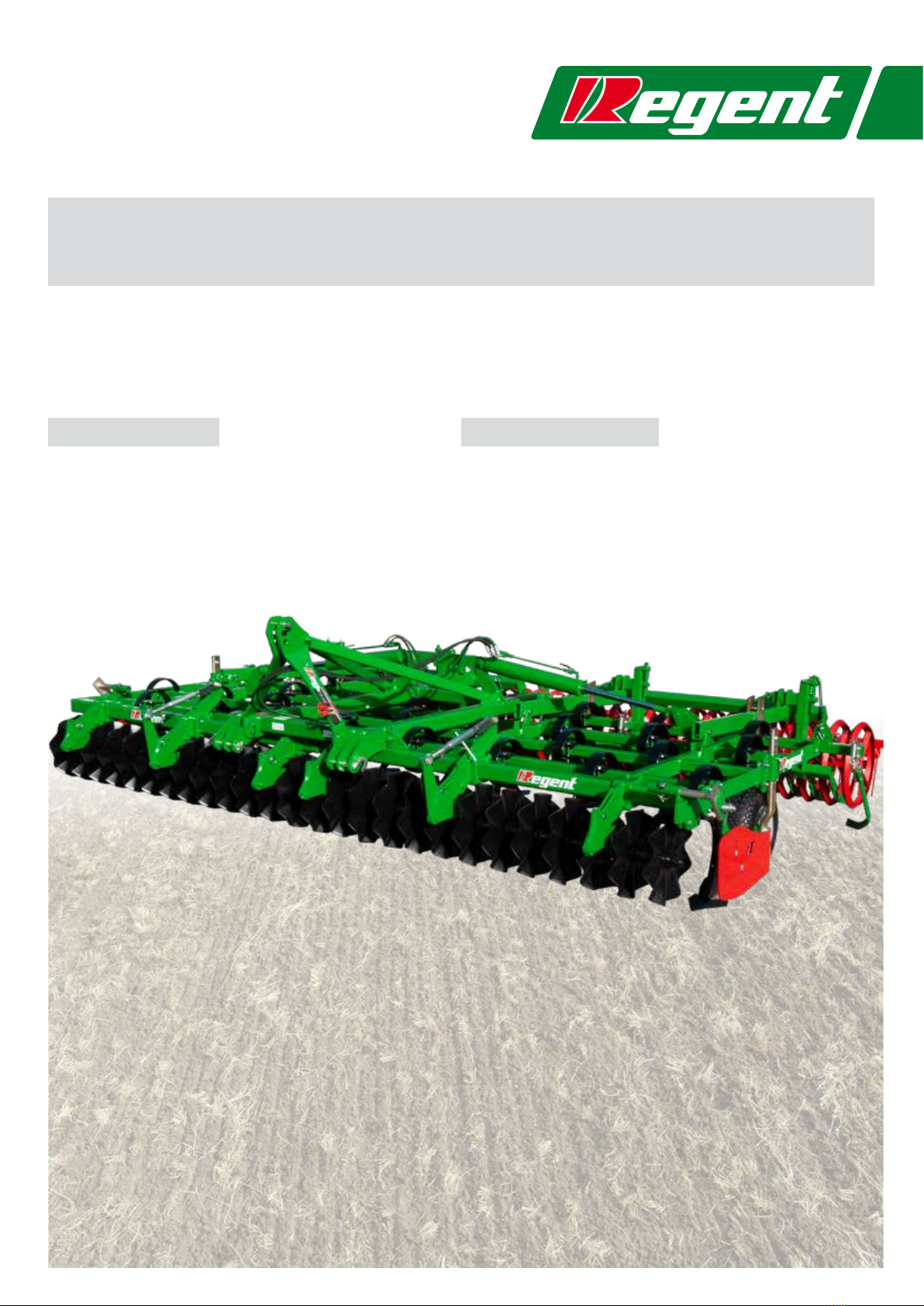
REGULATIONS OF GENERAL SECURITY AND
ACCIDENT PREVENTION
Beforeusingyournewmachineforthersttime,pleasereadallinstructionscarefullyandoperateinaccordancewiththe„Generalsaf-
etyandaccidentpreventionregulations“ofthemanufacturerandthoseofthelegislatorofyourcountry.Themanufacturerdeclinesall
liabilityiftherulesbelowarenotfollowed.Ifyouhaveanyquestionsaboutthesafetyregulations,pleasecontactanauthorizeddealeror
thefactorycustomersupportofRegentPugfabrikGmbH.
5www.regent.at