Testing/Troubleshooting
Check that both Power A and Power B Green LEDs are on. If they are not lit, check the input power
connections.
Check that the Green LEDs on each of the two isolated power modules are on. If they are not lit, check
module connections. If the connection is secure, replace the module.
Check that the Green Fieldbus LED is on. If it is not lit, check the Fieldbus cable and H1 host connection for
short circuit.
If a system alarm is generated, check all LEDs on the FPS units in the alarm circuit. Follow the instructions
above.
Operation
During normal operation, the green Power In A, Power In B, Fieldbus, and Power On LEDs should be lit.
If any of these LEDs are not lit, follow the instructions in the Testing/Troubleshooting section.
Maintenance Requirements
The FPS-I and FPS-2 contain no user serviceable parts. No maintenance is required. Non-functioning units
should be returned to the manufacturer for replacement or repair.
2221 Yew Street
Forest Grove, Oregon 97116 USA
(503) 357-5607 or (800) 382-3765
Fax (503) 357-0491
www.relcominc.com
500-272 Rev E.0
For Further Information
Contact your local MTL representative or Relcom, Inc. as listed at the bottom of this page.
Page 3 of 3
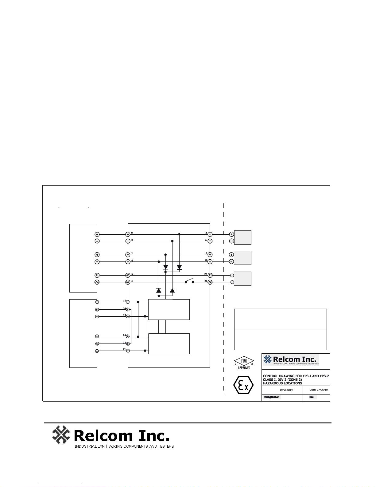
Power
Supply 1
Power
Supply 2
24 VDC Power Supply (Typical)
Vout (Max) <= 30 V, Vout (Min) >= 18V
Install According to Power Supply
Instructions to Ensure Maximum
Voltage Output is not Exceeded
Installation must be in accordance with the National Electrical Code
(NFPA 70, Article 504), ANSI/ISA-RP12.6, and CEC Part 1.
Part Numbers:
FPS-I (FPS-RCT and two FPS-IPM)
FPS-2 (FPS-RC and two FPS-IPM)
Minimum Wire Requirements: 24 AWG Stranded.
WARNING:
EXPLOSION HAZARD - DO NOT DISCONNECT
EQUIPMENT UNLESS POWER HAS BEEN SWITCHED
OFF OR THE AREA IS KNOWN TO BE NON-HAZARDOUS.
AVERTISSEMENT:
RISQUE D'EXPLOSION - AVANT DE DECONNECTER
L'EQUIPMENT, COUPLER LE COURANT OU S'ASSURER
QUE L'EMPLACEMENT EST DESIGNE NON DANGEREUX.
HAZARDOUS (CLASSIFIED) LOCATION NON-HAZARDOUS LOCATION
Class I, Division 2, Groups A, B, C, D, T4
Class I, Zone 2 IIC T4 (US only)
Ex nA, IIC, T4 (Canada and CENELEC only)
-40 C <= Tamb <= 50 C
TO BE INSTALLED IN AN IP 54 OR BETTER ENCLOSURE
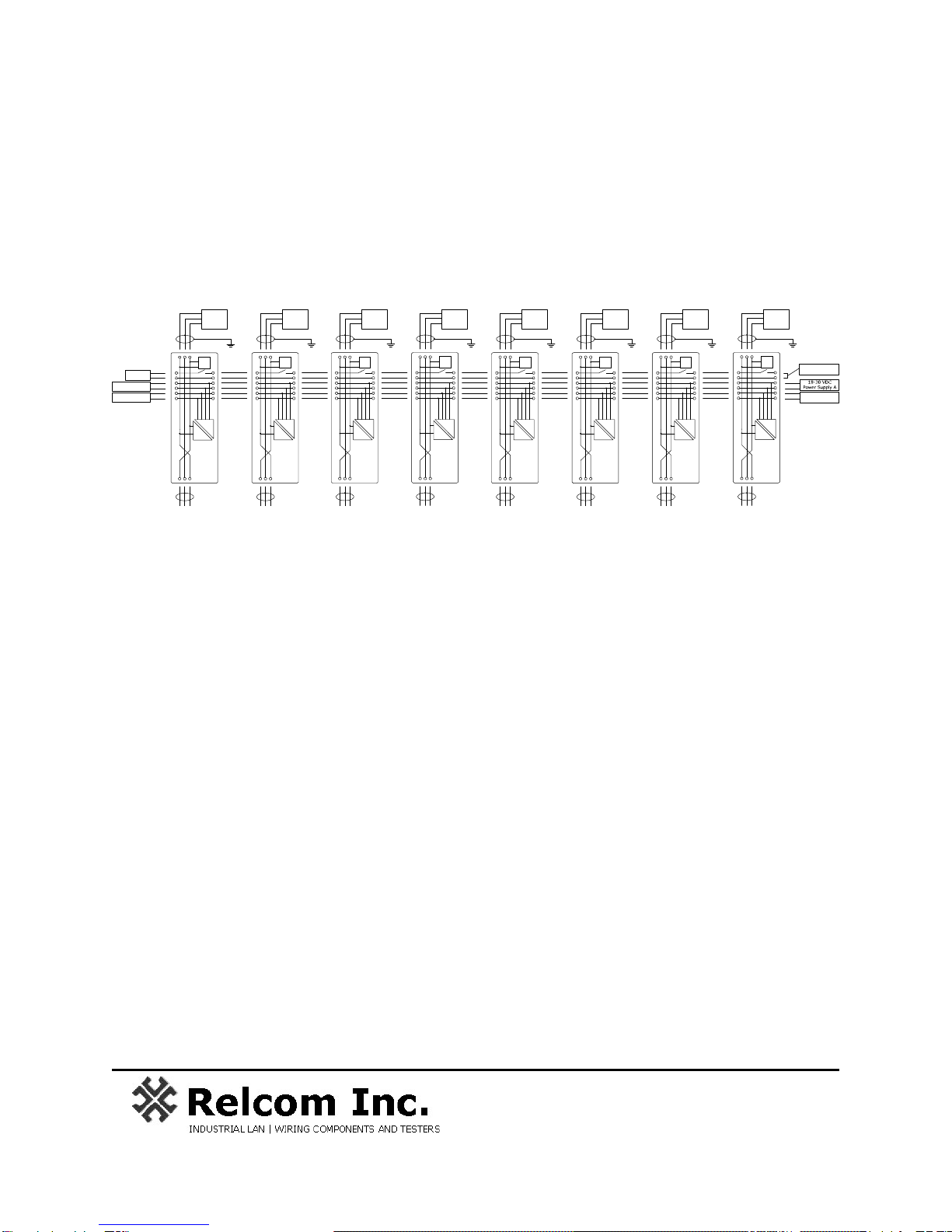
FPS-I or FPS-2
FPS-RC or FPS-RCT
FPS-IPM
Plugged into Socket
FPS-IPM
Plugged into Socket
Fieldbus
Segment
(Connector
blocks, devices,
terminators, host,
etc.)
Additional
FPS-I or
FPS-2
Units
Fieldbus Output
(+/- Power and Shield)
Power Supplied to Backplane must be fused for
8 A Circuitry.
2221 Yew Street, Forest Grove, Oregon 97116 USA
Title:
Approved By:
+
Control
System
Alarm/