TEXIO PR-A Series User manual

INSTRUCTION MANUAL
REGULATED DC POWER SUPPLY
PR-A SERIES
PR18-1.2A
PR18-3A
PR18-5A
PR36-3A
B71-0040-01

■About Brands and Trademarks
“TEXIO”is the product brand name of our industrial electronic devices.
All company names and product names mentioned in this manual are the
trademark or the registered trademark of each company or group in each country
and region.
■About the Instruction Manual
Permission from the copyright holder is needed to reprint the contents of this
manual, in whole or in part. Be aware that the product specifications and the
contents of this manual are subject to change for the purpose of improvement.

CONTENTS
SAFETY ································································· Ⅰ-Ⅳ
1. OUTLINE ....................................................................................1
2. FEATURES .................................................................................1
3. SPECIFICATION.........................................................................2
4. PERCAUTION FOR USE............................................................ 4
5. EXPLANATION OF PANELS......................................................5
5-1. Front panel....................................................................................................6
5-2. Rear panel.....................................................................................................7
6. OPERATION PROCEDURES .....................................................8
6-1. Stand-alone operation...................................................................................8
6-2. Serial connection...........................................................................................8
6-3. Parallel operation (master-slave control).......................................................9
7. TROUBLESHOOTING...............................................................11
Note.
This instruction manual is described for four models.
(PR18-1.2A,PR18-3A,PR18-5A,PR36-A)
Refer to item applied to your product.

I
USING THE PRODUCT SAFELY
■Preface
To use the product safely, read instruction manual to the end. Before using this
product, understand how to correctly use it. If you read the manuals but you do
not understand how to use it, ask us or your local dealer. After you read the
manuals, save it so that you can read it anytime as required.
■Pictorial indication
The manuals and product show the warning and caution items required to safely
use the product. The following pictorial indication is provided.
Pictorial
indication
Some part of this product or the manuals may show this
pictorial indication. In this case, if the product is
incorrectly used in that part, a serious danger may be
brought about on the user's body or the product. To use
the part with this pictorial indication, be sure to refer to the
manuals.
WARNING
!
If you use the product, ignoring this indication, you may get
killed or seriously injured. This indication shows that the
warning item to avoid the danger is provided.
CAUTION
!
If you incorrectly use the product, ignoring this indication,
you may get slightly injured or the product may be
damaged. This indication shows that the caution item to
avoid the danger is provided.
Please be informed that we are not responsible for any damages to the user or to
the third person, arising from malfunctions or other failures due to wrong use of
the product or incorrect operation, except such responsibility for damages as
required by law.

II
USING THE PRODUCT SAFELY
WARNING
!
CAUTION
!
■Do not remove the product's covers and panels
Never remove the product's covers and panels for any purpose.
Otherwise, the user's electric shock or fire may be incurred.
■Warning on using the product
Warning items given below are to avoid danger to user's body and life and avoid
the damage or deterioration of the product. Use the product, observing the
following warning and caution items.
■Warning items on power supply
●Power supply voltage
The rated power supply voltages of the product are 100, 120, 220 and 240VAC.
The rated power supply voltage for each product should be confirmed by
reading the label attached on the back of the product or by the “rated”column
shown in the instruction manual. The specification of power cord attached to
the products is rated to 125VAC for all products which are designed to be used
in the areas where commercial power supply voltage is not higher than
125VAC. Accordingly, you must change the power cord if you want to use the
product at the power supply voltage higher than 125VAC. If you use the
product without changing power cord to 250VAC rated one, electric shock or
fire may be caused. When you used the product equipped with power supply
voltage switching system, please refer to the corresponding chapter in the
instruction manuals of each product.
●Power cord
(IMPORTANT) The attached power cord set can be used for this
device only.
If the attached power cord is damaged, stop using the product and call us or
your local dealer. If the power cord is used without the damage being
removed, an electric shock or fire may be caused.
●Protective fuse
If an input protective fuse is blown, the product does not operate. For a
product with external fuse holder, the fuse may be replaced. As for how to
replace the fuse, refer to the corresponding chapter in the instruction manual.
If no fuse replacement procedures are indicated, the user is not permitted to
replace it. In such case, keep the case closed and consult us or your local
dealer. If the fuse is incorrectly replaced, a fire may occur.

III
USING THE PRODUCT SAFELY
■Warning item on Grounding
If the product has the GND terminal on the front or rear panel surface, be sure to
ground the product to safely use it.
■Warnings on Installation environment
●Operating temperature and humidity
Use the product within the operating temperature indicated in the “rating”
temperature column. If the product is used with the vents of the product
blocked or in high ambient temperatures, a fire may occur. Use the product
within the operating humidity indicated in the “rating” humidity column. Watch
out for condensation by a sharp humidity change such as transfer to a room
with a different humidity. Also, do not operate the product with wet hands.
Otherwise, an electric shock or fire may occur.
●Use in gas
Use in and around a place where an inflammable or explosive gas or steam is
generated or stored may result in an explosion and fire. Do not operate the
product in such an environment. Also, use in and around a place where a
corrosive gas is generated or spreading causes a serious damage to the
product. Do not operate the product in such an environment.
●Installation place
Do not insert metal and inflammable materials into the product from its vent
and spill water on it. Otherwise, electric shock or fire may occur.
■Do not let foreign matter in
Do not insert metal and inflammable materials into the product from its vent and
spill water on it. Otherwise, electric shock or fire may occur.
■Warning item on abnormality while in use
If smoke or fire is generated from the product while in use, stop using the
product, turn off the switch, and remove the power cord plug from the outlet.
After confirming that no other devices catch fire, ask us or your local dealer.

IV
USING THE PRODUCT SAFELY
■Input / Output terminals
Maximum input to terminal is specified to prevent the product from being
damaged. Do not supply input, exceeding the specifications that are indicated
in the "Rating" column in the instruction manual of the product. Also, do not
supply power to the output terminals from the outside. Otherwise, a product
failure is caused.
■Calibration
Although the performance and specifications of the product are checked under
strict quality control during shipment from the factory, they may be deviated more
or less by deterioration of parts due to their aging or others.
It is recommended to periodically calibrate the product so that it is used with its
performance and specifications stable. For consultation about the product
calibration, ask us or your local dealer.
■Daily Maintenance
When you clean off the dirt of the product covers, panels, and knobs, avoid
solvents such as thinner and benzene. Otherwise, the paint may peel off or
resin surface may be affected. To wipe off the covers, panels, and knobs, use a
soft cloth with neutral detergent in it.
During cleaning, be careful that water, detergents, or other foreign matters do not
get into the product.
If a liquid or metal gets into the product, an electric shock and fire are caused.
During cleaning, remove the power cord plug from the outlet.
Use the product correctly and safely, observing the above warning and caution items.
Because the instruction manual indicates caution items even in individual items,
observe those caution items to correctly use the product.
If you have questions or comments about the manuals, ask us or E-Mail us.

1
1. OUTLINE
The PR-A Series is a serial control type regulated DC power supply. It is a constant
voltage/current power supply whose output can be varied from 0 up to the rated
values.
It is a compact unit which, provided with both voltage and current calibrated meters,
allows both voltage and current to be monitored simultaneously. In terms of
operability, the unit enables high precision, continues variability via coarse and fine
adjust knobs.
We are confident that the unit’s design conceived with the user’s convenience in
mind to enable advantages such as arrangement in easy-to-use configurations and
its reliability will satisfy your needs very well.
With the PR-A Series, multiple units of the same model can be connected in parallel
to set up a “one- control”master/slave configuration having increased current output.
2. FEATURES
○The PR-A Series is a constant voltage/current supply which features extremely
low voltage and load fluctuation and ripple noise.
○Controls the output on and off by using output switch.
○The unit features separate voltage and current meters so that both voltage and
current can be monitored simultaneously.
○Output voltage and current can be adjusted continuously to any desired values.
Furthermore, the voltage can be preset easily and precisely using coarse and
fine adjust knobs.
○The constant current circuit operators to protect against overload and output
shorting. The limiting current can be preset from 0 up to the rated current, and
the unit can also be used as a constant current supply.
○The units enables “one-control”operation via connection in series, or via parallel
connection in a master/slave configuration.
○Using an optional rack-mounting adapter (RK-604), the PR Series can be
installed on a EIA or JIS rack.

2
3. SPECIFICATION
Item
PR18-1.2A
PR18-3A
PR18-5A
PR36-3A
Output Voltage
(continuously variable、coarse and fine adjusts)
0V to 18V
0V to 36V
Output current(continuously variable)
0A to 1.2A
0A to 3A
0A to 5A
0A to 3A
Constant voltage characteristics
Input fluctuation ( for surge of AC±100%)
0.01%+2mV(3.8mV)
0.01%+2mV(5.6mV)
Load fluctuation(for surge of 0% to 100%)
0.01%+2mV(3.8mV)
0.01%+3mV(4.8mV)
0.01%+2mV(5.6mV)
Ripple noise、rms(10Hz to 1MHz)※1
0.5mV rms
Ripple peak(peak-to-peak)※1
2mVp-p
Transient response
(Output current 5% to 100%)
100μs Typical
Temperature coefficient
150ppm/℃Typical
Constant current characteristics
Input fluctuation (for surge of AC±100%)
2mA
Load fluctuation(for surge of 0% to 100%)
15mA
Ripple noise、rms(10Hz to 1MHz)※1
2.4mArms
6.0mArms
10mArms
6.0mArms
Ripple peak(peak-to-peak)※1
3.6mAp-p
12mAp-p
15mAp-p
12mAp-p
Temperature coefficient
500ppm/℃Typical
Instrumentation
Voltmeter(2.5-level-F.S.)
18V
36V
Ammeter(2.5-level-F.S.)
1.2A
3A
5A
3A
Constant-voltage operation indicator
Green CV LED goes on
Constant-current operation indicator
Red CC LED goes on

3
Item
PR18-1.2A
PR18-3A
PR18-5A
PR36-3A
Function
OUTPUT ON / OFF switching
Turn the output on and off.
Serial connection (independent control mode)
Can be connected in series (within limits of ground proof voltage.)
Parallel operation (master-slave mode)
Can be operated in “one‐control” parallel configuration (only with other machines of same model)
OUTPUT
Polarity
Positive or negative ground possible
Output terminal (color)
+(red)、-(white)、GND(black)
Ground proof voltage
±250VDC
Operating conditions
Operating Temperature/Humidity Range
0 ℃to 40 ℃、10% to 85%R.H.
Storage Temperature/Humidity Range
-20 ℃to 60 ℃、10% to 85%R.H.
Cooling mechanism
Natural convection
Power consumption
VA / W (For rated load of AC 100V)
Approx. 60VA/45W
Approx.125VA/100W
Approx. 200VA/165W
Approx. 225VA/170W
Input Voltage
Voltage、Frequency
AC100V/120V/200V/220V/240V ±10%、50Hz/60Hz
Dimensions and weight
Dimensions mm (hight×width×depth)
147×104×180
147×104×215
147×138×230
147×138×230
Max. Dimensions mm (hight×width×depth)
161×108×200
167×108×265
167×142×290
167×142×290
Weight
Approx. 3.8kg
Approx. 5.7kg
Approx. 8.1kg
Approx. 8.6kg
Accessory items
CD-ROM(Instruction manual)
※1 Measured with positive or negative grounded
Circuit and ratings subject to change without notice due to development in technology.

4
4. PERCAUTION FOR USE
WARNING
!
1) Confirming the supply voltage
*Use this unit within the specified range. The unit’s rated voltage is single-phase
100/120/200/220/240VAC ±10% at 50/60Hz.
*The rated voltage is indicated on the specification and name plate located
beside the input connector on the rear panel.
2) Do not remove cover or panel
The user never open the case panel whatever may happen.
If the user needs to open case for replacing the fuse, changing the source voltage
or repairing the internal circuit or parts, please contact your dealer or our
distributor.
CAUTION
!
1) Precautions for connection of output terminals.
*This units is a floating type power supply. For ordinary use, be sure that the
MASTER/SLAVE switch on the rear panel is set to MASTER, and that either the
(+) output terminal or the (-) output terminal is connected to the GND terminal
(case GND) via the shorting bar.
2) Output current value setting
*To set the constant current value, short-circuit output terminal (+) and (-) and
deliver the output current
3) Set-up environment
*Be sure to use this unit within the specified ambient temperature range of 0 to
40 ℃.
*Because the unit is cooled by natural convection, do not place objects on top,
place the unit on or near any heat-emitting device, or use multiple units in any
stacked configuration. Also use the unit in an environment that is as well
cross-ventilated as possible.
5
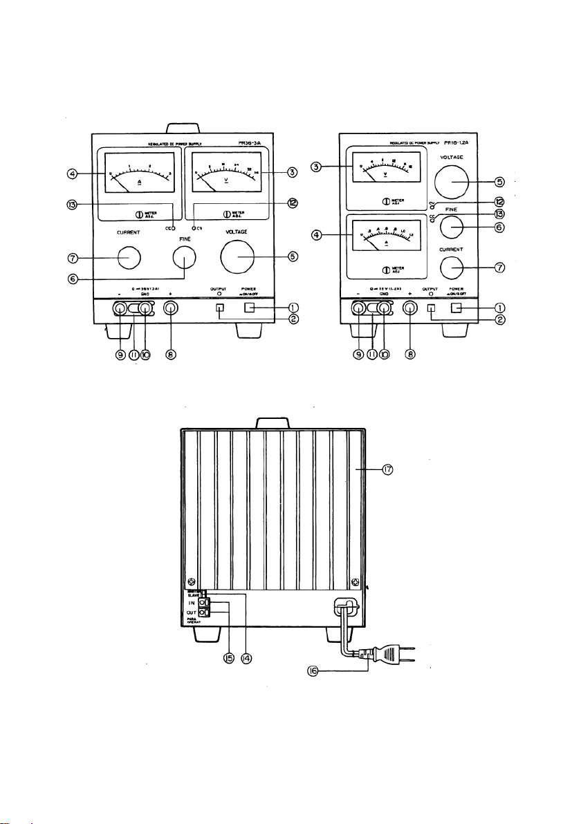
5. EXPLANATION OF PANELS
Figure1.
Figure2.

6
5-1. Front panel
①POWER ON/OFF
The power switch. The power supply should be on and operating when this switch
is depressed.
②OUTPUT switch
Turns the output on and off.
When the output is turned on, the OUTPUT LED goes on.
③Voltmeter
ADC voltmeter that indicates the output voltage.
④Ammeter
ADC ammeter that indicates the output current.
⑤VOLTAGE COARSE
Coarse adjust knob for the output voltage.
⑥VOLTAGE FINE
Fine adjust knob for the output voltage.
⑦CURRENT
Knob for setting the current value in the constant current mode. It can be used to
set limiting value for the output current.
⑧Output terminal (+)
Terminal for tapping of (+) output voltages.
⑨Output terminal (-)
Terminal for tapping of (-) output voltage.
⑩GND terminal
The ground terminal, it is connected to the main chassis. Normally, this terminal
for connected to either the (+) or (-) terminal with short bar.
⑪Short bar
Normal use, this bar connects between GND and output(+) or output (-) terminal.
⑫CV LED(Green)
The LED keeps lighting in process of constant- voltage operation.
⑬CC LED(Red)
The LED keeps lighting in process of constant-current operation.

7
5-2. Rear panel
⑭MASTER/SLAVE switch
Used during “one-control”parallel operation in the master/slave configuration.
During normal operation, the switch should be set to MASTER. (For details, see
section 6-3;“Parallel Operation”)
⑮IN/OUT terminals for parallel operation
Control terminals for use in the “one-control”parallel operation mode.
⑯Power cable
Approx. 2 meter-long power cable, equipped with standard wall plug.
⑰Heat sink
A heat dissipater for the transistors, be careful as this area can became quite hot
during operation.

8
6. OPERATION PROCEDURES
6-1. Stand-alone operation
*When using the power supply in stand-alone, simply operate by manipulation of
the panel switches as needed. However , be sure that the MASTER/SLAVE switch
is set to MASTER.
6-2. Serial connection
*Two or more units of the power supply can be hooked up in series to achieve in
increase in output voltage. The final output will be the sum of the outputs of the
individual units. In this situation, however, care must be taken that the voltage of
neither of the terminals with respect to the chassis GND exceeds the ground proof
voltage.
*In the case of serial operation of two units (both same model);
a. For connection as in Fig. 4, the output voltage, but output current will be limited
to within the value specified for a single unit.
b. For connection as in Fig. 5, where an intermediate point is hooked up to ground,
the configuration can be used as a plus/minus power supply.
GND
+
-
E1
GND
+
-
E2
+
-
E0
E0E1
=+E2
Connection of GND
For positive ground(dotted line)
For Negative ground(solid line)
LOAD
GND
+
-
E1
GND
+
-
E2
+
-
+E 1
-E 2
Intermediate point is
hooked up to ground.
LOADLOAD
Figure3. Figure4.

9
6-3. Parallel operation (master-slave control)
*Two or more units of the same machine can be hooked up in parallel to give an
increase in output current. The total output current will be the sum of the output
currents of the individual machines.
*In parallel operation, one machine will act as the master and all others will act
slaves. The output voltages and output currents are all set from the master
machine.
*When hooking the machines up in parallel, be sure that all the power ON/OFF
switches are OFF.
HOOK-UP PROCEDURE;
1)Turn the power switches of the master unit and slave unit(s) all to “OFF”.
2)Turn the MASTER/SLAVE switch (located on the back panel) on all the slave units
from “MASTER” to “SLAVE”.
3)Hook up the parallel operation-use terminals (IN/OUT, located on the rear panel) of
the master and slave(s) as shown in Figure 5.
4)For connecting the output terminals of each of the machines to the load, use all
cords of the same length.
5)For (+) and (-) grounding to the GND terminal, hook up the master and slave
machines via the terminals on the panels.
Figure 7 shows the output connection scheme for (-) grounding.
6)Set the voltage and current knobs of all the slave unit(s) it the maximum setting.
7)Turn the power switches of the master unit and slave unit(s) all to “ON”. Control
the output voltage and current as desired via the voltage and current knobs on
master unit.
*When the output goes to 0 amperes in the parallel operation mode, output voltage
can no longer be controlled by the master machine. Be sure to keep a current
flowing that is several % of the rated current.
Hook-up of rear panel terminals in the parallel operation mode
MASTER
MASTER
SLAVE
IN
OUT
SLAVE(1)
MASTER
SLAVE
IN
OUT
SLAVE(2)
MASTER
SLAVE
IN
OUT
Figure5.

10
Hook-up front panel terminals in the parallel operation modes.
- +
G
- +
G- +
G
I2
I3
I1
+
-
I0
MASTER SLAVE(1) SLAVE(2)
LOAD
Note ; I0= I1+ I2+ I3
The voltage presets on all the slave machines are set to maximum. The master
operates in constant voltage mode and the slaves operate in constant current
mode. Figure 6.
For instruction on how to achieve parallel operation of multiple machines of different
models, please contact your dealer or our distributer.
*Connection of Terminal on Rear Panel
While pressing on the slit portion of the terminal with an ordinary (-) screwdriver,
insert the connecting cable into the round jack. When insertion is complete,
remove the screwdriver.
The cable will remain locked into the terminal even after the screwdriver is
removed.
Insert the
connecting cable
Push with (-) screwdriver
10mm
φ0.4~1.0 (AWG26~18), 0.3~0.75m ㎡
Figure7.
Note : When using stranded (twisted) cable, the connector should be attached by
soldering.

11
7. TROUBLESHOOTING
Problem
Indicators orAreas to check
Cause
Power supply will
not go on.
Power ON lamp does not light
up.
*Poor connection of
power cord, or broken
wire.
*Bad power switch.
*Fuse meltdown.
No output voltage.
Voltmeter does not move.
*Circuit malfunction.
No output current.
Ammeter does not move.
*Circuit malfunction.
Excessively large
output.
Output voltmeter and ammeter
readings do not decrease.
*Bad power transistor or
control mechanism.
*Circuit malfunction.
Unstable output.
Input voltage is wrong.
Machine is vibrating.
Strong magnetic or electrical
field nearby.
*Operating outside the
rated voltage range.
*Oscillations due to
special load type.
*Remove from source of
oscillations.
WARNING
!
The user never open the case panel whatever may happen.
If the user needs to open the case for replacing the fuse, changing the source
voltage or repairing the internal circuit or parts, please contact your dealer or our
distributor.

7F Towa Fudosan Shin Yokohama Bldg.
2-18-13, Shin Yokohama, Kohoku-ku,Yokohama, Kanagawa, 222-0033 Japan
http://www.texio.co.jp/
This manual suits for next models
4
Table of contents
Other TEXIO Power Supply manuals

TEXIO
TEXIO PDS20-10A User manual

TEXIO
TEXIO PS-A Series User manual

TEXIO
TEXIO PFR-100M250 Manual

TEXIO
TEXIO PSW Series User manual

TEXIO
TEXIO PU6-100 User manual

TEXIO
TEXIO PAR-A Series User manual

TEXIO
TEXIO PU Series User manual

TEXIO
TEXIO PU6-200 User manual

TEXIO
TEXIO PD18-10AD User manual

TEXIO
TEXIO PU6-200 User manual


