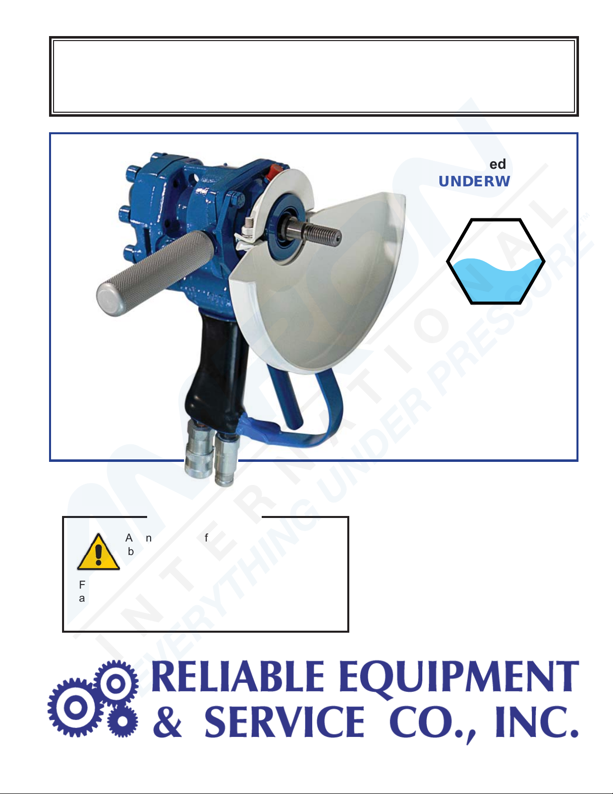
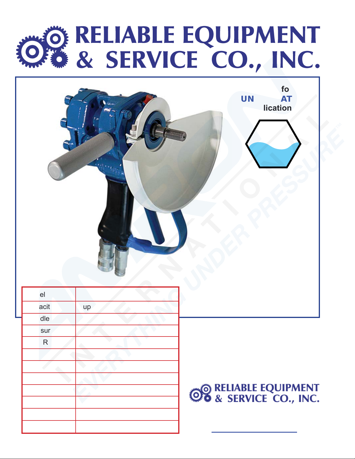
Reliable Equipment & Service REL-GR-9 Manual

1
OPERATORS’ GUIDE
REL-GR-9 Manual 07-15
Sealed for
UNDERWATER
applications
UW
WARNING
All information found in this guide must
be read and understood before use or
testing of this tool.
Failure to read and understand these warnings
and safe handling instructions could result in
severe personal injury and or death.
REL-GR-9
9” Hydraulic Grinder
Shown with optional
REL-370-6FP
Quick Couplers
Grinding
Cutting
Cleaning
Buffing
Polishing
De-scaling
Barnacle Removal

2
CAUTION
The information in this manual is intended to guide the user
in the use and application of this tool. It is not intended as
a substitute for proper training and experience in safe work
practices for this type of equipment.
Consult your supervisor or safety personnel if you have any
questions regarding the safe operation of this tool.
DISTRIBUTED BY
REGISTRATION
UPON RECEIPT OF THIS TOOL, COMPLETE THE REGISTRATION BELOW.
COMPANY _____________________________________________________________
ADDRESS _____________________________________________________________
________________________________________________________________________
PHONE _______________________ FAX____________________________________
SERIAL NUMBER _______________________________________________________
DATE OF PURCHASE ___________________________________________________
DEALER NAME _________________________________________________________
THIS SYMBOL INDICATES ITEMS OF EXTREME IMPORTANCE.
Safety of user and others may be in jeopardy if these instructions
are not read and understood.

3
TABLE OF CONTENTS
DISTRIBUTION & REGISTRATTION ................................................... 2
TABLE OF CONTENTS ........................................................................ 3
GENERAL INFORMATION & LITERATURE ........................................ 4
TOOL & HYDRAULIC SOURCE SPECIFICATIONS ............................ 5
GENERAL SAFETY INFORMATION ................................................. 6-8
HOSES AND FITTINGS (General Information) .................................... 9
HOSES - Fittings, Connectctions, Installation .................................... 10
DAILY MAINTENANCE & HYDRAULIC FLUIDS ............................... 11
OPERATIONAL SAFETY .................................................................... 12
PRE-OPERATION ............................................................................... 13
OPERATION ........................................................................................ 14
POST OPERATION, WHEEL REPLACEMENT, & INSPECTION ........15
ADAPTER, LABELS, & LOCAL REGULATIONS ............................. 16
ASSEMBLY DRAWINGS & PARTS ............................................... 18-19
OPERATION & MAINTENANCE RECORDS ...........................17, 20-21
CONTACT INFORMATION ............................................................... 22
DESCRIPTION
The REL-GR-9 hydraulic 9” Grinder has broad applications for the utility, line
construction, D.O.T., and underwater construction industries.
The well balanced tool feels comfortable and secure. The trigger is designed to
be responsive in a heavily gloved hand, enabling the user controlled operation.
The REL-GR-9 hydraulic 9” Grinder uses standard 9 inch (23 cm) abrasive
discs for cutting, grinding, and polishing applications. A variety of specialized
accessories are also available to further expand the capabilities of this tool.
If you have any questions regarding the information found
in this manual please contact RELIABLE EQUIPMENT at the address,
phone or fax numbers found on the back cover of this manual.

4
301 Ivyland Road • Warminster, PA 18974
Phone: 800-966-3530 • Fax: 215-357-0363
www.Reliable-Equip.com
REL-GR-9
9” Hydraulic Grinder
Grinding
Cutting
Cleaning
Buffing
Polishing
De-scaling
Barnacle Removal
Shown with optional
REL-370-6FP
Quick Couplers
Sealed for
UNDERWATER
applications
A variety of wheels, discs, brushes
and accessories are available meet
any demand, making the REL-GR-9
an indispensible addition to any
tool inventory.
Model REL-GR-9 Hydraulic Grinder
Capacity up to 9” wheel / 23 cm
Spindle 5/8 - 11 Threaded
Pressure 1,000 - 2,500 psi 70 - 176 Bar
Flow Range 4 - 12 gpm / 38 lpm
Optimum Flow 10 gpm / 38 lpm (2,700 rpm)
Porting 8 SAE O-ring
Connector 3/8” adaptors (x2)
Motor Gear Drive
Weight 14 lbs. / 6.4 kg
Length 11 inch / 28 cm
Width 12 inch / 30.5 cm
UW

5
TOOL SPECIFICATIONS
Length .............................................................................................11” (28 cm)
Width ........................................................................................... 12” (30.5 cm)
Weight ......................................................................................... 14 lb. (6.4 kg)
Disc Diameter (Max.) ....................................................................... 9” (23 cm)
Spindle ................................................................................ 5/8 - 11 Threaded
Output Speed (Max.) .........................................................................2,700 rpm
Pressure/Return Ports ............................................................. 8 SAE O-ring
Connector ................................................................................... 3/8” Adaptors
Drive ............................................................................................. Gear Driven
Hyd. System Type ..............................................Open Center, HTMA Type II
SPECIFICATIONS
Hydraulic Power Source
Flow: Min. .......................................................................4 gpm (5.1 lpm)
Recommended .....................................................10 gpm (38 lpm)
Flow Range .................................................. 4-12 gpm (15-45 lpm)
Operating Pressure Min. ...................................................1,000 psi (70 bar)
Operating Pressure Max. .................................................2,500 psi (176 bar)
Pressure Relief Setting .............................................2,000 psi Max. (138 bar)
Back Pressure........................................................................200 psi (13.8bar)
Filtration ................................................................................ 10 microns Max.
Hydraulic System ........................................................................Open Center
Fluid Temperature, Max. .......................................................... 140O F (60O C)
* Checked with Flowmeter on Pressure Line
WARNING
DISASSEMBLYOFTHISTOOLISNOTRECOMMENDED
SERIOUS INJURY OR DEATH COULD RESULT FROM
IMPROPER SERVICE OR REPAIR OF THIS TOOL.
REPAIR AND/OR SERVICE OF THIS TOOL MUST BE DONE BY A
CERTIFIED TECHNICIAN OR AN AUTHORIZED REPAIR CENTER.
Contact RELIABLE EQUIPMENT at 800-966-3530 for an authorized repair center.

6
WARNING
BEFORE USING THIS TOOL, READ THE WARNINGS
and the recommended practices described in this manual.
Failure by the operator to read and fully understand these
warnings will leave this person unqualified to use and
operate this tool. Property damage, severe personal injury,
and/or death could result by not following these warnings.
Eye Protection
These warnings will appear in appropriate locations when they are pertinent to the
particular subject being shown. Read each one carefully and follow them strictly.
WARNING
Always wear eye protection to avoid
injury from flying debris or hydraulic
oil leaks. Failure to do so can result in
serious personal injury.
Hard Hat
WARNING
Always wear a hard hat to avoid injury
from falling debris. Failure to do so
can result in serious personal injury.
Hearing
Protection
WARNING
Always wear hearing protection,
to avoid hearing loss due to long
term exposure to high noise levels.
Foot
Protection
WARNING
Always wear foot protection.
Failure to do so can result in serious
personal injury.
Dust Mask
WARNING
Always wear a dust mask. Failure
to observe this warning may result
in serious health issues and/or
breathing difficulty.
WARNING
Protective
Gloves
Always wear protective gloves
Failure to do so can result in serious
personal injury.

7
WARNING
Safety
DO NOT attempt to make any changes to any of the component
parts or accessories when connected to the power source.
DO NOT adjust, inspect, or clean tool while the tool is connected to
the power source. The tool could accidentally start up and cause
serious injury.
DO NOT lock the tool in the On Position. In an emergency, serious
damage or injury could occur during the time required to stop the tool.
Safe Operation & Care
USE THIS TOOL FOR ITS INTENDED PURPOSE ONLY
Any other use can result in injury or property damage.
INSPECT TOOL BEFORE USE. Replace any worn, damaged
or missing parts. A damaged or improperly assembled tool may
malfunction, injuring operator and/or nearby personnel.
INSPECT HYDRAULIC HOSES AND COUPLINGS before each
use. Repair or replace if any cracking, leakage, wear or damage
is is found. Worn or damaged hoses may fail resulting in personal
injury or property damage.
CLEAR WORK AREA of all bystanders and unnecessary personnel
before operating this tool. Remove any potential tripping hazard or
restrictions to free movement.
KEEP ALL PARTS OF THE BODY AWAY FROM MOVING PARTS.
Failure to observe this warning could result in serious injury.
WARNING
Oil Injection Injury
Hydraulic oil or fluid under the skin is a serious injury.
Oil under pressure can penetrate the skin and may cause
dismemberment or loss of life. Seek medical assistance
immediately if such an injury should occur.
Always wear safety gloves, eye protection and all required
safety equipment when operating or handling this tool.
DO NOT use fingers or hands to attempt to locate a leak.
DO NOT handle hoses or couplers while system is pressurized.
NEVER open or service the system before depressurizing.
WARNING

8
Safe Handling
HYDRAULIC FLUID MAY CAUSE SKIN IRRITATION.
Prevent hydraulic fluid from making contact with skin.
IN THE EVENT OF SKIN CONTACT immediately wash thoroughly.
Failure to observe this warning could result in injury.
CAUTION
Vibration Hazard
Apply just enough pressure to control the tool operation. Applying
excess pressure to the tool may cause operator discomfort or
temporary numbness.
Failure to observe this warning could result in serious injury.
CAUTION
Electrical Shock Hazard
Use only certified non-conductive hoses and fittings.
Always wear and use the necessary clothing, equipment and
safety practices to protect against electrical shock. Failure to
follow these rules can result in serious personal injury or death.
WARNING
CAUTION
General Safety
Ensure that all fellow employees and bystanders are clear
and protected from possible injury caused by this tool or the
operations being performed. Persons in close proximity could
be injured and property damaged if the tool were to malfunction.
This tool should always be used within the limits and purposes
stated by the product manufacturer. Abuse or usage beyond the
manufacturers’ intended purposes could cause damage to the tool
and severe injury to the operator and or bystander.
Burn Hazard
Do Not connect or disconnect tool, hoses or fi ttings while power
source is running or while hydraulic fl uid is hot.
Hot hydraulic fl uid may cause serious burns.
Failure to observe this warning could result in serious injury.
WARNING

9
HOSES AND FITTINGS
Care must be exercised in the use of hose and fi ttings for use on hydraulic tools, especially
in confined areas. Any obstruction or abrasive surrounding could damage the hose and cause a
serious accident. Always use the recommended hose for the tool that is being used. Always consult
the dealer or distributor for the correct hoses and purchase from him to ensure, from a safety
standpoint that the materials used in the manufacture of the hoses is to the correct specification
for the application. Fittings must meet the standards established by the industry to adequately
assure safety. Poor quality or low rated fittings are not to be used. They invite a serious accident.
Length: Hose must be the correct length for the general use of the tool or for the specific function it is
to provide. Pressure surge is an important factor in the selection of hoses. The hose should be rated
above the expected surge pressure to ensure adequate safety. Hoses that are too long will have a
tendency to coil, kink, or move in multiple directions creating a safety hazard. Hoses that are too long
will rub or chafe against the ground or projecting objects, seriously shortening the life of the hose. It
may be advisable to carefully restrain a hose which is temporarily too long for the current application.
Pressure surge can cause whipping, and seriously damage the hose. Always keep the hose length
as short as possible for the operation which is it intended.
Size: The hose must be large enough to carry the pressurized flow of fluid to the end application
without creating undue heat generation or excessive turbulence. These factors could cause excessive
wear to the hose from any or all of the above reasons.
Pressure: Hose selection must be made so that the recommended maximum operating pressure is
greater than the system pressure. A surge or sudden drop in pressure will cause the hose to deteriorate
faster if the maximum pressure of the hose is significantly below the surge pressure. A hose with a
top rate of pressure as the line pressure of the installation is not an accepted safety practice. Always
err on the side of safety.
Temperature: Hose can be seriously damaged by passing over or near hot objects. Avoid any situation
that will heat the hose. Serious damage and/or failure will occur.
Unusual Applications: Careful thought and research should precede installation of hoses. Thorough
and protected testing, with appropriate safety guards, must be done to avoid injury before general use.
Connections: Hoses must have the proper end fittings in order to mate correctly with connectors.
Worn or damaged connectors and worn end fittings on the ends of the hose can cause a failure.
Pressure surge can cause a slow or sudden failure at the connection causing serious damage or injury.
Safety Check: Before using any installation, perform a thorough checkout to determine if any of the
above or unforeseen problems occur. Initial testing with safety guards is an invaluable safety precaution.
Always consult the distributor or manufacturer for the correct specifications regarding any of
the items discussed above. The correct hoses and fitting are available from your supplier.
There exists the potential for SHOCK or ELECTROCUTION in using anything other than certifi ed non-
conductive hoses and hydraulic oil with dielectric properties near ENERGIZIZED ELECTRICAL LINES.
Hoses and fittings used with this tool must comply with S.A.E.
J1273 recommended practice for selection, installation, and
maintenance of hose assemblies.
FAILURE TO COMPLY WITH THESE WARNINGS
COULD RESULT IN SEVERE BODILY INJURY.
WARNING

10
HOSES AND FITTINGS
There exists the potential for shock in using anything other than
certified nonconductive hoses and hydraulic oil with dielectric
properties, and when using system components near energized
electrical lines.
Failure to recognize these conditions could cause electrocution.
Hoses and fittings used with this tool must comply with S.A.E. J1273 which
covers recommended practice for selection, installation, and maintenance of hose and
hose assemblies. The correct hoses and fi ttings are available from your supplier.
WARNING: Failure to comply with these warnings could result in severe bodily injury.
WARNING
UNIT/HOSE CONNECTIONS
ALWAYS SHUT OFF pump/power source and move flow selector
to OFF before connecting or disconnecting system components.
ALWAYS DEPRESSURIZE hydraulic system before slowly
disconnecting this unit or any of the systems components.
ALWAYS TIGHTEN couplings completely. Loose or improperly
tightened couplings will not allow fluid to pass through the
hose creating a blockage in the supply or return line.
ALWAYS INSPECT HOSES AND CONNECTORS before connection
to tool. Replace or repair if any leakage is evident. Leakage is a sign
of deterioration in component parts. Worn or leaking parts must be
repaired or replaced, or tool damage or severe injury could result.
WARNING
HOSE INSTALLATION
Care must be taken to assure the correct connection of the hoses
to the pressure and return ports.
Connect the return hose to the return port on the power source,
then to the return port on the tool.
Connect the pressure hose to the pressure port on the tool, then
to the pressure port on the power source.
Operation with hydraulic fl ow reversed can cause malfunction.
Failure to fully comply can result in severe injury or death.
CAUTION

11
DAILY MAINTENANCE /INSPECTION
The life, reliability, and safety of the tool is dependent on proper maintenance.
Ensure the hydraulic system control valve is in the “OFF” position and hoses are
disconnected before inspecting or servicing the grinder.
Clean & Inspect all surfaces including handle, trigger, spindle, fittings, hoses, disc,
and guard. Inspect tool for dirt build-up, corrosion, wear, and damage.
All the above items must be replaced with new parts if signs of wear are evident.
Loose, worn or damaged parts can cause tool to malfunction during operation.
Make sure the proper disc is installed for the application being performed.
Check that the maximum operating speed of the disc/wheel is equal to or greater than
the rated shaft speed of the grinder. Wheels must be rated at 2,700 rpm minimum.
Inspect Wheel or blade for wear or damage (i.e. chips, cracks, surface wear, bending)
For maximum tool performance replace disc/wheel or accessory if wear or damage
is evedent. (Refer to “INSTALLING & REMOVING GRINDING WHEEL” as needed)
Inspect accessory handle, Handle should be clean and securely fastened to the grinder.
Inspect for cracked hoses and leaking fittings. Never use hands to check for leaking.
All the above items must be replaced with new parts if signs of wear are evident.
Check fluid level of the power source reservoir frequently.
FLUID CONTAMINATION: Cover the ends of fittings with a dust cap when disconnected.
This will help keep the fluid from contamination.
MONTHLY MAINTENANCE: Inspect per Appendix A, SAE Standard J1273, 5/86 for
hose or fi tting damage such as wear, cracks or leakage, replace the necessary parts.
NOTE: Keep Label Set clean and legible. Replace decals when necessary.
Post Operation Maintenance (Underwater Models & Applications ONLY)
The tool must be cleaned and lubricated with waterproof grease after every day of use.
The handle body and motor assemblies are sealed and do not require maintenance
unless they are malfunctioning.
Salt water applications may require more frequent maintenance.
HYDRAULIC FLUIDS
All hydraulic fluids that meet these listed specifications or the listed HTMA specifications may
be used for this tool.
S. U. S.
@ 100OF (38OC) ......................................................................... 140 TO 225
@ 210OF (99OC) ....................................................................... 40 minimum
FLASH POINT ...................................................... 340OF min. (170O C min.)
POUR POINT ......................................................... -30OF min. (-34OC min.)

12
OPERATIONAL SAFETY WARNINGS
USE ALL APPROPRIATE & APPLICABLE PERSONAL SAFETY EQUIPMENT as required
by the operating company and local safety regulations.
INSPECT HYDRAULIC HOSES AND FITTINGS for wear or deterioration every day.
Replace all parts that show signs of leaking, wear, or damage.
NEVER CONNECT fi ttings unless power/pump source is turned off or disconnected.
KEEP ALL PARTS OF THE BODY AWAY from moving parts of the tool when connected to
the power source for the tool. Do not wear long hair or lose clothing that may become drawn
into moving components.
KEEP ALL BODY PARTS AWAY from path of debris discharge. Discharge may also be
defl ected by objects. Clear area and/or take additional precausions to ensure operator safety.
MAKE SURE there is no person in close proximity to you or the tool who could be injured by
any operation being performed or fl ying debris expelled by the tool.
DO NOT overextend your position by overreaching or unbalancing the footing necessary to
maintain physical control of your body oand the tool.
ALWAYS MAINTAIN a fi rm grip on the tool to avoid having the tool slip out of the hands during
an operation, causing a serious personal injury and/or property damage.
DO NOT apply excessive pressure, side load or apply any type of indirect force.
Cutting wheel or blade may be damaged creating a potentially dangerous situation.
SHOCK, ELECTRICAL: Using this tool in an energized electrical environment could be
dangerous to the user. Failure to observe this warning may result in electrocution.
DEPRESSURIZE THE UNIT before attempting to disassemble, connect, or disconnect
any of the components. Check oil temperature before disconnecting or disassembling this
unit. A serious burn could result from this exposure.
SEE A DOCTOR IMMEDIATELY, if a hot oil injury should occure.
SEE A DOCTOR IMMEDIATELY, if a pressurized oil injury should occure.
Infection or serious reaction could result from any hydraulic pressure injury.
USE THIS TOOL FOR THE MANUFACTURERS’ INTENDED PURPOSES ONLY.
OBSERVE CLOSELY ALL SAFETY RULES FOR A PARTICULAR JOB CLASS
THE PURCHASER/OWNER of this unit must be certain that all the users of this unit are properly
trained in it’s use and in compliance with all appropriate industrial codes and/or practices.
FAILURE TO HEED THESE WARNINGS COULD RESULT IN
SERIOUS PERSONAL INJURY AND/OR PROPERTY DAMAGE.
WARNING
Operation/Safety methods may vary in accordance
with the working guidelines established by each utility
or contractor.
For your own safety, ensure that you fully comply with
all safe operation guidelines required by your employer.

13
PRE-OPERATION
If you are unsure of the proper use or application for this tool consult a supervisor.
Only use accessories that conform to the specifi cations given in this manual.
NOTE: This saw rotates in the Counter clockwise direction, expelling debris forward away
from the operator. Do not allow others to enter the area in front of the tool during operation.
1. It is important to ensure that any couplers used are the correct type, and the fl ow is
going in the right direction. Although the tool may function with the pressure and return
lines reversed, the tool’s performance, SAFETY, and service life will be adversely affected.
IMPORTANT! The operator of the tool MUST know the type of hydraulic system on which the
tool is being used. This tool is factory confi gured to operate on Open Center Systems.
Failure to observe all warnings & instructions may result in property damage, or personal injury.
2. Install the proper wheel/blade for intended application. Blade direction is Counterclockwise.
Check that the maximum operating speed of the cutting wheel is equal to or greater than
the rated shaft speed of the grinder. Wheels must be rated at 2,700 rpm minimum.
(Refer to “INSTALLING & REMOVING GRINDING WHEEL” as needed)
3. Check Trigger Mechanism - Trigger should operate smoothly and freely between
ON and OFF positions.Trigger should disengage grinder when released.
Safety catch on handle should prevent engagement of the trigger unless the
catch is fully depressed.
4. Check that the handle is clean and fully screwed into the bracket.
5. Wheel Guard - Inspect the wheel guard for structural damage.
Adjust the wheel guard as needed. Ensure that the screws are tightened before operation.
6. Ensure that the hydraulic power source is operating within the recommended range
for both Pressure of 1,500-2,000 psi (70-140 bar) and Flow of 7-9 gpm (26-34 lpm)
NOTE: Use of a calibrated Flow Meter and Pressure Gauge (REL-FPG) is recommended.
5. Ensure that the power source is equipped with a relieve valve set to 2,100 psi (145 bar)
ENSURE THAT POWER SUPPLY IS OFF BEFORE CONNECTING THE TOOL.
6. Squeeze the trigger to relieve any internal pressure.
7. Connect appropriate hydraulic hoses to the tool beginning with the return hose.
(Refer to Hoses & Fittings on Page 9 & 10)
8. Start the hydraulic system and move the control valve to the “ON” position.
9. Operate the grinder in a safe position at no load for 30 seconds. If O.K. proceed.
If considerable vibration, noise or other defects are detected, STOP operation immediately.
Dust created during the demolition of certain materials may
contain hazardous substances. (i.e. Silica, Lead, Asbestos, etc.)
Inhalation of such materials may result in serious injury, cancer, or death.
An understanding of the materials you are cutting will allow you to protect
yourself, co-workers, and others within the work area.
WARNING
Follow correct safety procedures and comply with all national, state or provisional
health and safety regulations relating to them.
If appropriate arrange for the SAFE disposal of these materials by a qualifi ed person.

14
OPERATION
If you are unsure of the proper use or application for this tool consult a supervisor.
The operator must be familiar with the intended work area. Avoid potential hazards and
prohibited work areas such as dangerous terrain, excessive slopes, or unmarked utilities.
Only use accessories that conform to the specifi cations given in this manual.
Do not allow others to enter the discharge area around the tool during operation.
WARNING: Never operate a tool without the wheel guard in place.
1. Clamp or secure the work and support it on both sides of the cut.
2. Start the hydraulic tool system & move the control valve to the “ON” position.
COLD WEATHER OPERATION - Run power unit at low speed to preheat the hydraulic fl uid.
The oil should be at or above 50O (10OC) with a viscosity of 400 SSU (82 cs) before operation.
WARNING: Know the location of buried or covered services BEFORE starting the work.
Operate the tool in well ventilated areas ONLY.
Do not operate the tool near flammable materials. Do not cut or grind on vessels containing
combustible substances. Sparks can ignite flammable or combustible substances.
3. Grip the tool with both hands during startup and operation and be sure you have full
balance before starting grinder rotation.
NOTE: Always keep your body away from the “plane of rotation” of the grinding wheel.
4. Always start the grinder with the disc/wheel away from the work surface.
Press the safety switch into the handle and slowly squeeze the trigger.
Start hydraulic flow low and slowly increase to a level that produces efficient operation,
but allows the operator to maintain full balance and control.
NOTE: Run the tool at operating speed for at least one minute at the beginning of each shift,
or after a new disc/wheel is installed. Never exceed the max. speed marked on the disc.
4. With the disc rotating, start the operation. Holding the tool securely move the tool gently
into the work with consistent pressure. Do not bump the tool into the workpiece.
Never cock, jam or wedge the disc during the operation.
5. Allowing the disc to do the work without slowing the rotation speed.
Forcing the operation may increase operator fatique.
Pinching due to heat expansion may cause disc breakage.
(Refer to INSTALLING & REMOVING GRINDING WHEEL on page 15)
NOTE: If a wheel breaks while operating the tool, investigate the cause of the failure
before continuing the operation.
NOTE: Inspect the guard and collars for damage after any disc breakage on tool.
6. Release the Trigger and the Safety Latch and allow tool to stop.
WARNING: Never carry the tool or put it down while the disc is still moving.
7. Move the hydraulic system control valve to the “OFF” position and shut down system.
CAUTION: Work piece may be HOT and/or sharp. Use your personal protection equipment.
8. Disconnect the hydraulic hoses from the tool.
First the INPUT (Supply), then the Output (Return) hose.
9. Place dust plugs or caps on hose ends, couplers and/or tool ports as needed.
10. Remove the disc after use.

15
POST OPERATION CARE & STORAGE
Disconnect the hydraulic hoses from the tool.
First the INPUT (Supply), then the Output (Return) hose.
Place dust plugs or caps on hose ends, couplers and/or tool ports as needed.
Remove the disc after use.
NOTE: Never transport or store the tool with the cut-off wheel mounted on the saw.
TOOL CARE
Clean tool to remove dirt, grease or debris. Dry with compressed air or clean dry cloth.
Replace any damaged or missing safety labels and tags before storing.
Store the tool in a clean dry place.
DISC/WHEEL CARE
All abrasive discs/wheels are breakable.
Care should be taken to prevent damage during handling and storage.
Clean and inspect the wheel before storing.
Clean wheel to remove dirt, grease & debris.
Dry thoroughly.
Store wheels on a flat rigid surface of steel or comparable material.
Do not subject to high humidity, water or liquids.
Avoid excessive heat, freezing, or temperatures low enough to cause condensation if
temperature is increased.
INSTALLING & REMOVING GRINDING WHEEL
Inspect for chips, cracks, wear, or damage. Replace the wheel if it is worn or damaged.
1. Remove and set aside the jam nut from the output shaft.
2. Position the grinding wheel over the shaft.
3. Screw the jam nut down onto the spindle shaft. Tighten the nut securely by using two
open-end wrenches, one wrench on the flats of the spindle shaft, the other wrench on
the jam nut. NEVER over-tighten by impacting either wrench with a hammer or mallet.
4. Remove the grinding wheel by loosening the jam nut. (Reverse of Step 3)
PERIODIC INSPECTION & MAINTENANCE - For maximum performance, reliability and
SAFETY of the tool, periodically check the following components.
DRIVE-SHAFT SPEED CHECK
The maximum rated speed of the Hydraulic Grinder is 2,700 rpm.
The rated speed of the disc must be equal to, or greater than that of the tool to ensure the
integrity of the wheel at maximum tool speed.
Use the hydraulic power supply normally used with the cut-off saw when conducting this test.
Excessive speed may be caused by increasded fl ow. Refer to SPECIFICATIONS on page 5.
Check the speed of the motor output shaft. (Every 100 hours of operation is recommended)
The test should be performed only by a trained, experienced technician.
Maintain a record of the checks.

16
USE OF A DEPRESSED CENTER WHEEL ADAPTER - Use of a depressed center wheel
adapter is required when using a cupped or depressed center wheel.
BEFORE USING THIS PRODUCT
READ THE SAFETY WARNINGS
and recommended practices described
in the manual. Failure by the operator to
read and fully understand the warnings
will leave this person unqualifi ed to use
and operate the tool.
Failure to observe all warnings and instructions could result
in property damage, severe personal injury, and/or death.
WARNING
SPECIFICATIONS
Flow Range: 4 - 12 gpm
Recommended 7-10 gpm
Recommended
Operating Pressure
1,500-2,000 psi
LOCAL SAFETY REGULATIONS
Supervising authorities should develope additional precautions relating to the specifi c work
and local safety regulations. Record pertinent local and/or regonal codes below.
KEEP LABEL SET CLEAN - REPLACE WORN OR DAMAGED LABELS BEFORE STORAGE

19
Date Ser. # Hydraulic Source ID# Hyd. Flow Speed/RPM
DRIVE SHAFT SPEED CHECK
If you have any questions regarding the information
found in this manual please contact RELIABLE EQUIPMENT at the address,
phone or fax numbers shown below.

17
REL-GR-9
9” GRINDER
PARTS LIST
5
1
3
67
4
2
10 8
9
12
11
13
15
14 16 17 18
19
20
21
18 22 23 24
25
26
28
30
34
36
32
35
37
34
36
27
31
33
42
40
38
39
43
43
42
41
44
9
45
53
Coupler Set
46
48
49
50
51
52
47

18
GR29 PARTS LIST
1 GR901 1 Jam Nut
2 GR902 2 Hex Bolt, Guard
3 GR903 2 Nut
4 GR904 1 Clamp, Guard
5 GR905 1 Wheel Guard
6 GR906 4 Cap Screw
7 GR907 2 Lockwasher
8 GR908 1 Capscrew
9 GR909 2 Nut
10 GR910 1 Trigger Guard
11 GR911 1 Handle
12 GR912 2 Dead Handle Bracket
13 GR913 1 Shaft Seal
14 GR914 1 Grease Fitting
15 GR915 1 Bearing Carrier
16 GR916 1 Retaining Ring
17 GR917 1 Ball Bearing
18 GR918 2 Retaining Ring
19 GR919 1 O-Ring
20 GR920 1 Spindle Shaft
21 GR921 1 Woodruff Key
22 GR922 1 Back-up Washer
23 GR923 1 Back-up Ring
24 GR924 1 O-Ring
25 GR925 8 Capscrew
26 GR926 8 Washer
27 GR927 1 Plug
28 GR928 1 Motor Cap Assy.
29 GR929 1 O-Ring
30 GR930 1 Dowel Pin
31 GR931 1 Idler Shaft
32 GR932 1 Drive Gear
33 GR933 1 Idler Gear Assy.
34 GR934 2 Bushing
35 GR935 1 Bushing
36 GR936 1 O-Ring
37 GR937 1 Main Housing
38 GR938 1 Retaining Ring
39 GR939 1 Reversing Spool
40 GR940 1 Setscrew
41 GR941 1 Valve Keeper
42 GR942 2 Back-up Ring
43 GR943 2 O-Ring
44 GR944 1 Capscrew
45 GR945 1 Trigger
46 GR946 1 Rod Wiper
47 GR947 1 O-Ring
48 GR948 1 Spool Cap
49 GR949 1 O-Ring
50 GR950 1 Headed Push Pin
51 GR951 1 Spool Assy.
52 GR952 1 Spring
53 GR953 2 Adapter
GR9SK 1 SEAL KIT

20
Date Depth Operation Service Inspection
Underwater Operation/Service Records
If you have any questions regarding the information
found in this manual please contact RELIABLE EQUIPMENT at the address,
phone or fax numbers shown below.
NOTES
Table of contents
Popular Grinder manuals by other brands

Bosch
Bosch Professional GWS 8-125 C operating instructions

EINHELL
EINHELL TE-AG 230 operating instructions

SUHNER ABRASIVE
SUHNER ABRASIVE UTG 8-R Technical document

Makita
Makita M0920 instruction manual

Toro
Toro STX-26 Operator's manual

Art's-Way Manufacturing
Art's-Way Manufacturing 6520 Operator's manual

tresnar
tresnar TAG-125/1200 Original instruction manual

Hitachi Koki
Hitachi Koki G13SB3 Handling instructions

Chicago Pneumatic
Chicago Pneumatic T025373 Operator's manual

Makita
Makita 9565PCV instruction manual

Northern Industrial Tools
Northern Industrial Tools 3343109 user manual

DeWalt
DeWalt D28885 instructions