Page 9
G. Installing and Wiring the Outdoor Power
Inlet Box (included in kit)
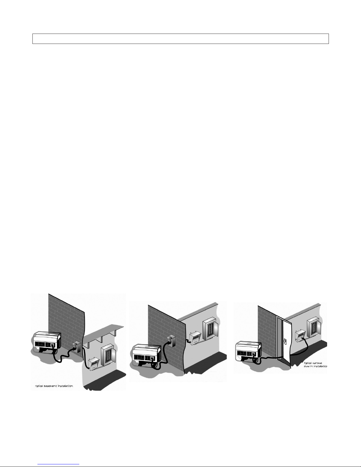
Since you will be operating your generator outdoors in a location
remote from your electrical load center, it is recommended that you
install an outdoor power inlet box on an exterior wall of your house.
Because it is hardwired directly to your transfer switch, the power
inlet box gives you the flexibility to locate your generator just about
anywhere.
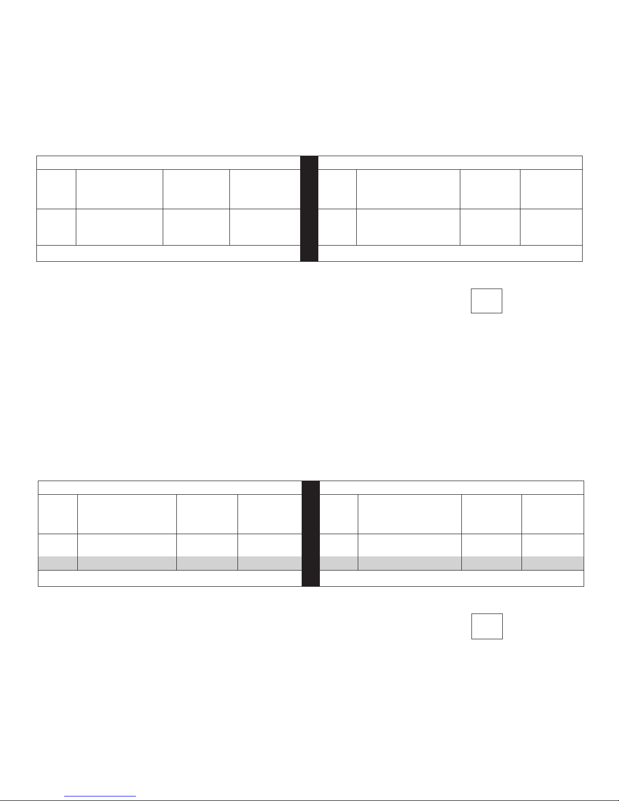
Reliance Controls Power Inlet Boxes are UL listed and can be used
with the following generator and building wire sizes:
Generator Size Power Inlet BoxBuilding Wire (100' or less)
Up to 7500 Watts PB30 (In kit) 10 gauge
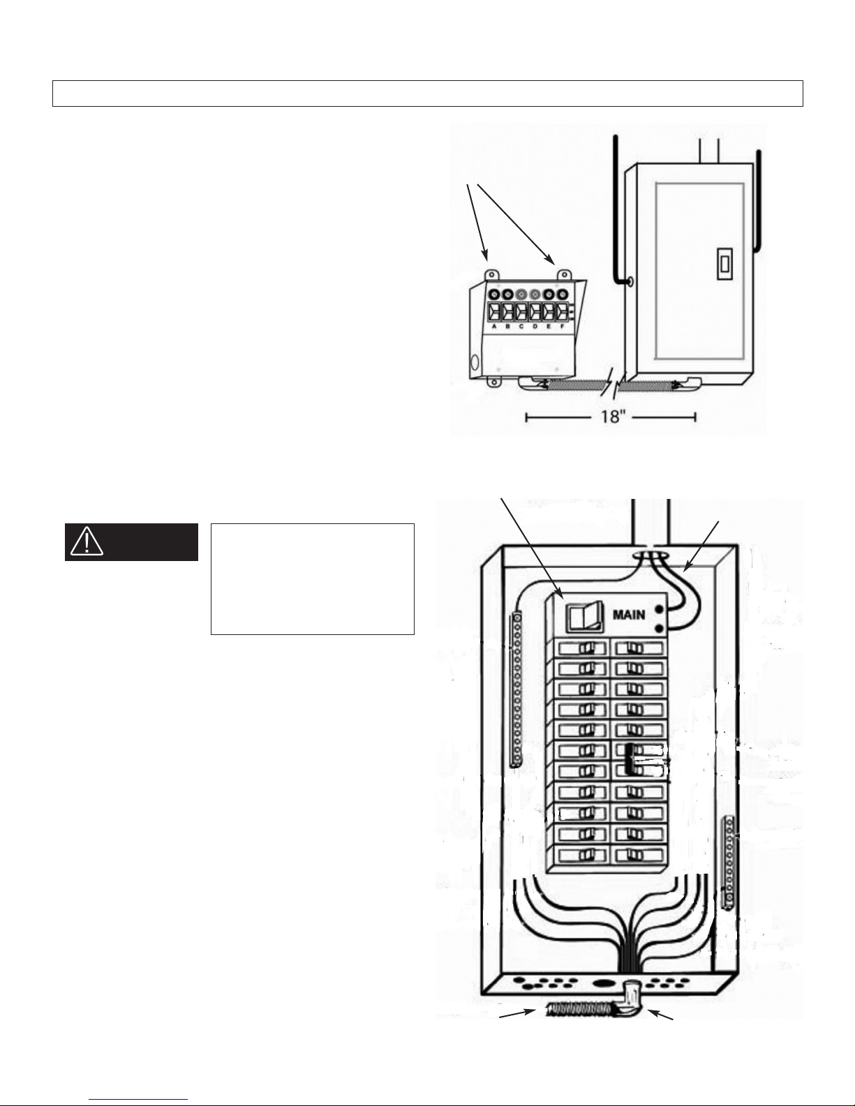
To install a Reliance Power Inlet Box (Figure 8):
1. Loosen the screw at the bottom front of the box and lift off the
cover.
2. Choose which knockout hole on the box is most convenient to
where you will be running the building wire into your house.
Remove the knockout with a screwdriver and hammer.
3. Plan to run enough building wire (check electrical codes for the
need for conduit) to reach your transfer switch, allowing extra
length for ease of wiring at the transfer switch end.
4. Using approved wiring methods, place a cable or conduit
connector (check codes) in the inlet box knockout hole and run
enough building wire into the box to allow easy wiring. Tighten
the connector.
5. Mount the back plate of the power inlet box where it will be
convenient. Use the three holes in the plate.
6. Strip 5/8” from each building wire lead. Loosen the green
grounding screw on the inside of the box and insert the stripped
end of the building wire ground under one side of the grounding
screw and retighten.
7. On the bottom of the inlet plug, insert the white wire into the
hole marked “W” and tighten the screw on the side of the plug.
Do the same with the red wire into the hole marked “X” and the
black wire into the hole marked “Y”.
8. Replace the cover of the power inlet box and tighten
the screw.
H. Wiring the Power Inlet Box to the
Transfer Switch
All Reliance Controls transfer switches are designed to allow
hardwiring between the outdoor power inlet box and the transfer
switch’s internal wiring compartment. This installation is the most
efficient, eliminates the need for longer generator power cords
running through your home to your transfer switch and eliminates
the need for an additional junction box.
To hardwire your transfer switch to the building wire from the power
inlet box (Figure 9A and 9B):
1. Remove the front bottom wiring compartment cover plate of the
transfer switch by unscrewing the two screws securing the plate
and then pulling out on the bottom of the plate. Once the plate
is removed, the wire leads necessary to connect the incoming
building wire can be easily accessed.
2. Punch out the knockout hole on the side of the transfer switch
wiring compartment.
3. Using approved wiring methods, place a cable or conduit
connector (check electrical codes) in the knockout hole, and pull
enough building wire into the inside of the wiring compartment
to provide sufficient working length. Tighten the connector.
4. Connecting the Wattmeters: Thread the black building wire
through the transformer ring attached to the left wattmeter
before connecting it to the black transfer switch wire. Likewise
thread the red building wire through the transformer ring
attached to the right wattmeter before connecting it to the red
transfer switch wire. Connect the green to green and white to
white wires with a red connector. Do not thread these wires
through the transformer rings (Figure 9B).
5. Complete the wiring by pushing the wires back into the unit,
putting the wiring compartment cover back in place and
replacing the screws that hold the cover plate.
Connecting the Wattmeters
Black wire through left
ring transformer
Red wire through right ring
transformer
Figure 8 Figure 9A Figure 9B