Relyon plasma Brush User manual

Table of contents
BA-KommUSB_EN / F0352200
June 2016
1
Operating instructions
USB communication package
BA-KommUSB_EN / F0352200

Table of contents
2
BA-KommUSB_EN / F0352200
Thank you for purchasing a high-quality relyon plasma GmbH product.
To get the best from your product, please read these instructions carefully.
Important!
Read these instructions carefully before assembling, installing and starting up the machine!
Always follow the safety instructions! Failure to follow the safety instructions may result in accidents,
serious injury and serious damage to the machine.
The product may only be started up and operated by trained and qualified persons!
Train your staff! The operator / user is responsible for ensuring that personnel have fully understood the
operation of the machine and the safety requirements.
© Copyright relyon plasma GmbH 2016.
All rights reserved. All rights reserved.
Text, images and diagrams and their layout are protected by copyright and other laws. Unauthorised copying and
distribution of this document and the utilisation and communication of its contents are strictly prohibited unless expressly
authorised. Offenders will be held liable for the payment of damages. All rights reserved in the event of a patent, utility
model or ornamental design registration being granted.
Original operating
instructions

Table of contents
BA-KommUSB_EN / F0352200
June 2016
3
1Safety.........................................................................................................................................4
1.1 Residual risks....................................................................................................................................4
1.2 Information and obligations for the operator .....................................................................................4
1.3 Intended use .....................................................................................................................................4
1.4 Impermissible operating conditions...................................................................................................5
2System description...................................................................................................................6
2.1 Function ............................................................................................................................................6
2.2 System overview ...............................................................................................................................6
2.2.1 Description of the components ...........................................................................................6
2.2.2 Scope of delivery ................................................................................................................7
3Transport / storage ...................................................................................................................7
4Unpacking and installation ......................................................................................................7
4.1 Unpacking .........................................................................................................................................7
4.2 Installation requirements ...................................................................................................................7
4.3 System component installation .........................................................................................................8
4.4 "Plasma control" installation software ...............................................................................................8
5Operation...................................................................................................................................9
5.1 Start-up..............................................................................................................................................9
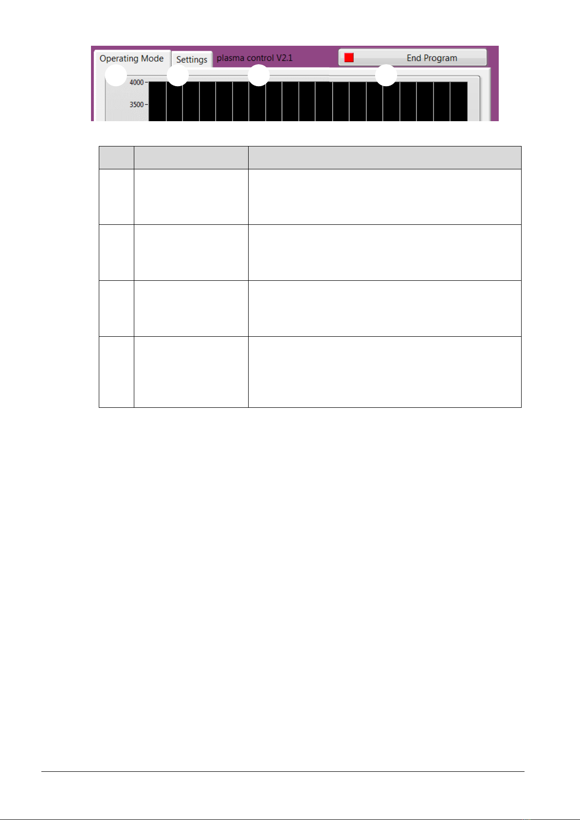
5.2 Operating the "plasma control" software...........................................................................................9
5.2.1 "Operating Mode" menu item............................................................................................11
5.2.2 "Settings" menu item ........................................................................................................13
5.2.3 Data recording sample file ................................................................................................14
6Environment............................................................................................................................15
6.1 Disposal ..........................................................................................................................................15

4
June 2016
BA-KommUSB_EN / F0352200
1Safety
The system was designed in accordance with the relevant international standards.
However, as with any technical product, hazards may arise if the system is not used
properly or is used for purposes other than its intended use.
Working with the system can be dangerous and may result in serious or fatal injury. It is
therefore essential to protect yourself and others.
In addition to the safety instructions in this document, you must also comply with general
safety standards.
Caution - Danger!
When working with the system, please note and observe the safety instructions and
requirements in these operating instructions because non-compliance may result in
serious or fatal injury.
1.1 Residual risks
This system has been manufactured in accordance with the current state of the art.
However, it is impossible to eliminate residual risks.
Always adhere to the following safety instructions:
Caution –Electrical voltage!
•Danger: 230 V. If damage is visible on the electrical connection, mains cable or
system:
- Do not start up the system.
- Have the damaged parts repaired by a qualified person or replace them.
Tripping hazard!
Lay the connection cables in suitable cable trays. Lay cables such that they do not
present a tripping hazard.
1.2 Information and obligations for the operator
•The system may emit interference.
- The system has been tested in accordance with EMC legislation.
- The operator must verify and assure electromagnetic compatibility with other
electrical and electronic equipment in the immediate vicinity of the system.
•Ensure that:
- Operating personnel have read and understood these operating instructions.
- Anyone working near the machine is made aware of the dangers and is provided
with the necessary protective equipment.
- Repairs are only carried out by qualified persons.
•In particular, make operating personnel aware of the safety instructions in this
document.
•Always keep the system in fully functional condition.
•Any modifications made to the machine will invalidate the operating licence and the
warranty. Exception: Such modifications are expressly authorised by the manufacturer.
1.3 Intended use
The system is intended solely for operation with the PS2000 high-voltage source and a
plasma generator from relyon plasma GmbH.

BA-KommUSB_EN / F0352200
June 2016
5
Coupled with a suitable plasma generator, the machine is intended solely for the plasma
treatment of surfaces (metals, textiles, glass and plastics) to activate, clean, coat or remove
residue at atmospheric pressure.
Under no circumstances may the system be used by non-trained persons.
1.4 Impermissible operating conditions
The system must not be operated under the following conditions:
•In explosive (Ex) zones
•In areas with severe build-up of dust
•Where there is excessive air humidity (>80% rel.)
•Where temperatures are outside of 0 –40 °C or 32 –104 °F.
•Where there are strong vibrations
Note!
Please also observe the information in the operating instructions of all additional
components connected to the system.

6
June 2016
BA-KommUSB_EN / F0352200
2System description
2.1 Function
The components of this system are the basic elements for communicating with a PS2000
current source using a Windows PC over USB.
2.2 System overview
2.2.1 Description of the components
No.
Components
1
PC/CAN Interface USB-to-CAN compact
2
CAN cable (length 2 m)
3
CAN terminal resistor (Sub-D)
4
CAN terminal resistor bushing (Sub-D)
5
USB stick with software
1
2
3
4
5

BA-KommUSB_EN / F0352200
June 2016
7
2.2.2 Scope of delivery
The scope of delivery includes the following components:
•PC/CAN Interface USB-to-CAN compact
•CAN cable (length 2 m)
•CAN terminal resistor (Sub-D)
•CAN terminal resistor bushing (Sub-D)
•USB stick with software
•Operating instructions
3Transport / storage
•Protect the system from dirt and foreign objects.
•Protect the system from impact.
4Unpacking and installation
4.1 Unpacking
•Carefully open the packaging.
•Take the components out of the packaging.
4.2 Installation requirements
Before installing the machine, the following points must be met:
•The components must be undamaged.
•If installing as a permanent installation or in a building, a suitable switch or circuit
breaker that satisfies national safety requirements (in Germany: VDE 0100) must be
fitted as an upstream all-pole cut-off device that will disconnect the system from the
power supply. This cut-off device should be fitted near the machine and must be easily
accessible to the user. The switch must also be labelled as the cut-off device for the
machine.
•Only a trained electrician may wire the system.
•Observe all installation requirements and safety notices for the additional machines
connected.
•PC system requirements (at least): - Windows XP, Windows 7
- 1 GB RAM
- 400 MB free storage space
- 1024x768 resolution
- USB connection

8
June 2016
BA-KommUSB_EN / F0352200
4.3 System component installation
To install the system, carry out the following steps in the order specified:
1. Connect the CAN terminal resistor (bushing) to the "USB-to-CAN" PC/CAN interface.
2. Connect the CAN cable to the CAN terminal resistor (bushing).
3. Connect CAN cable to the rear connection of the PS2000 current source.
4. Terminate the CAN bus on the PS2000 with the provided terminal resistor; if necessary,
also refer to the operating instructions of the PS2000 current source if necessary.
5. Set the PS2000 node number to "10."
6. Connect the "USB-to-CAN" PC/CAN interface to the USB connection of your PC.
7. Establish the emergency stop circuit for the PS2000 and all other connections of the
additional machines as described in the corresponding operating instructions.
The system is installed.
4.4 "Plasma control" installation software
To install the software, carry out the following steps in the specified order:
1. Insert the provided USB stick into the USB port on your PC.
1
2
5
3
4
6

BA-KommUSB_EN / F0352200
June 2016
9
2. Install the VCI driver by running the "VCI_Treiber_###.exe" file in the "VCI-Installer"
subfolder.
This may require administrator rights. Follow the instructions in the program to complete
the installation
3. Carry out the "setup.exe" file in the "plasma control V2.1" subfolder.
This may require administrator rights. Follow the program instructions to complete the
installation.
The software is installed.
5Operation
5.1 Start-up
To operate the system, the following points must be met:
- The main switch of the connected PS2000 current source must be switched on.
- The emergency stop circuit must be connected correctly.
- The CAN bus cables must be connected, both ends must be terminated with
terminal resistors and the correct CAN bus address (10) must be set at the rear side
of the current source.
- The baud rate of the current source must be 500 kBd.
- The software version of the current source(s) must be 4.03 or higher.
- The "USB-to-CAN" PC/CAN interface must be connected to the PC's USB
connection before the "plasma control" software is started.
- The "plasma control" software must be installed and started on the connected PC.
- The plasma generator must have a gas supply.
- All additional machines/components must be correctly connected.
If these points are met, you can use the software to control your plasma process using your
PC.
Please note that it is essential that a gas flow is present in order to operate the plasma
generator. The software does not test whether sufficient gas flow is present. This check
then has to be provided in the overall system.
Before activating the high voltage for plasma generation, there must be a gas flow through
the plasma generator for at least 2 seconds.
Attention –Damage to machine!
The plasma generator may be damaged if it is operated with no gas or too little gas.
- Never switch on the high voltage before sufficient gas is flowing through the plasma
generator!
5.2 Operating the "plasma control" software
The software is divided into two tabs: "Operating Mode" and "Settings".
The individual functions and commands are described below.

10
June 2016
BA-KommUSB_EN / F0352200
#
Menu item
Explanation
1
Operating mode
During operation, all necessary commands can be run
on the "Operating Mode" tab.
Further details can be found in 5.2.1
2
Settings
One-time settings for the storage location can be
entered under "Settings".
Further details can be found in 5.3.1
3
(Version number)
In the header, you can read off the version number of
the software (shown in V2.1)
4
End program
Please always be sure to close the program using the
"End Program" button.
If the program was not closed using this button,
restarting the computer is required to establish
communication again.
1
2
4
3

BA-KommUSB_EN / F0352200
June 2016
11
5.2.1 "Operating Mode" menu item
#
Menu item
Explanation
4
Plasma ON
(Plasma OFF)
Pressing this button activates/deactivates the high
voltage and the plasma on the plasma generator is
ignited/stopped. The button appears red during an
active plasma generation process.
To be able to start the plasma generation process,
there can be no error messages in the status field (#7).
5
Reset
The presence of an error message can be
acknowledged using this button. If an error message is
present, the button flashes red.
6
Datalog
Pressing this button starts the data recording process.
The button appears green during an active data
recording process.
7
Status
The current status messages are displayed in this field.
Additional information about the status messages can
be found in the operating instructions of the PS2000
current source.
4
5
6
7
9
8
10
11

12
June 2016
BA-KommUSB_EN / F0352200
8
(Comments field)
In this field, you can enter any text that is to be stored
with your measurement data. These entries can be
process parameters or identification numbers.
9
Power
This is the power set value input of the current source
in a percentage. You can select values between 70 and
100% and apply them by pressing "SET".
10
Frequency
This is the frequency set value input of the current
source in kilohertz (kHz). You can select values
between 40 and 65 kHz and apply them by pressing
"SET".
11
(Diagram/legend)
The currently measured operating parameters for
voltage U (in volts), current I (in milliamperes) and
power P (in watts) are displayed here for the last 60
seconds.

BA-KommUSB_EN / F0352200
June 2016
13
5.2.2 "Settings" menu item
#
Menu item
Explanation
12
Data Name Suffix
As an option, you can enter a desired suffix for the
data recording files here.
The suffix is appended to the part of the file name that
cannot be changed, which consists of the date and
time of the data recording.
The suffix field is populated with the text
"plasmacontrol" by default.
If no input is made, the file is named according to the
yyyymmdd_hhmmss_plasmacontrol.csv format
13
Data Safe Path
As an option, you can change the data path for the
data recording process.
If no change is made, it is stored automatically in the
standard working directory.
14
(Status window
file path)
Whether or not a valid data path was selected is
displayed here.
13
12
14

14
June 2016
BA-KommUSB_EN / F0352200
5.2.3 Data recording sample file
The file is stored in the selected directory or in the standard working directory in
accordance with the naming system described under point 5.2.2.
The file format is .csv with the ";" delimiter (semicolon).
A sample file is listed below to show an example of the content and the structure. All
standard settings have been retained for the sample file.
Sample file name: 20151217_171129_plasmacontrol.csv

BA-KommUSB_EN / F0352200
June 2016
15
6Environment
6.1 Disposal
Consider the environment.
Electrical and electronic equipment used must not be disposed of along with normal
waste.
- The machine contains valuable materials that can be recycled. Take the machine to a
suitable collection point.
relyon plasma GmbH
Weidener Strasse 16
93057 Regensburg
Germany
Phone: +49-941-60098-0
Fax: +49-941-60098-100
E-mail: info@relyon-plasma.com
www.relyon-plasma.com
Other manuals for Brush
1
Table of contents
Other Relyon plasma Conference System manuals