Relyon plasma Brush User manual

Inhaltsverzeichnis
BA-KommPN_EN / F0354700 Januar 2023 1
Operating instructions
Communication package
ProfiNet
BA-KommPN_EN / F0354700

2 BA-KommPN_EN / F0354700
Thank you for buying a high-quality relyon plasma GmbH product.
To get the best from your product, please read these instructions carefully.
Important!
Read these instructions carefully before assembling, installing and starting up the machine!
Always follow the safety instructions! Failure to follow the safety instructions may result in accidents,
serious injury and serious damage to the machine.
The product may only be started up and operated by trained and qualified persons!
Train your staff! The operator / user is responsible for ensuring that personnel have fully understood the
operation of the machine and the safety requirements.
© Copyright relyon plasma GmbH 2023.
All rights reserved. All rights reserved.
Text, images and diagrams and their layout are protected by copyright and other laws. Unauthorised copying and
distribution of this document and the utilisation and communication of its contents are strictly prohibited unless expressly
authorised. Offenders will be held liable for the payment of damages. All rights reserved in the event of a patent, utility
model or ornamental design registration being granted.
Original Operating
Instructions

Inhaltsverzeichnis
BA-KommPN_EN / F0354700 Januar 2023 3
1 Safety ......................................................................................................................................... 4
1.1 Residual risks .................................................................................................................................... 4
1.2 Information and obligations for the operator ..................................................................................... 4
1.3 Intended use ..................................................................................................................................... 5
1.4 Impermissible operating conditions ................................................................................................... 5
2 System description ................................................................................................................... 6
2.1 Function ............................................................................................................................................ 6
2.2 System overview ............................................................................................................................... 6
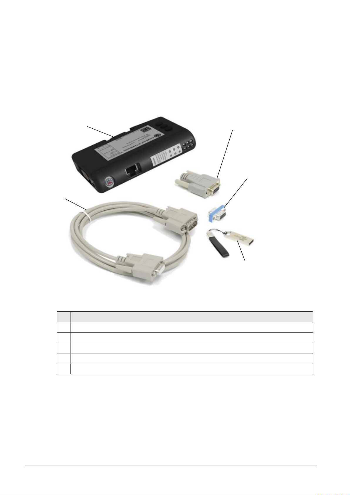
2.2.1 Description of the components ........................................................................................... 6
2.2.2 Scope of delivery ................................................................................................................ 7
2.2.3 Other hardware components needed ................................................................................. 7
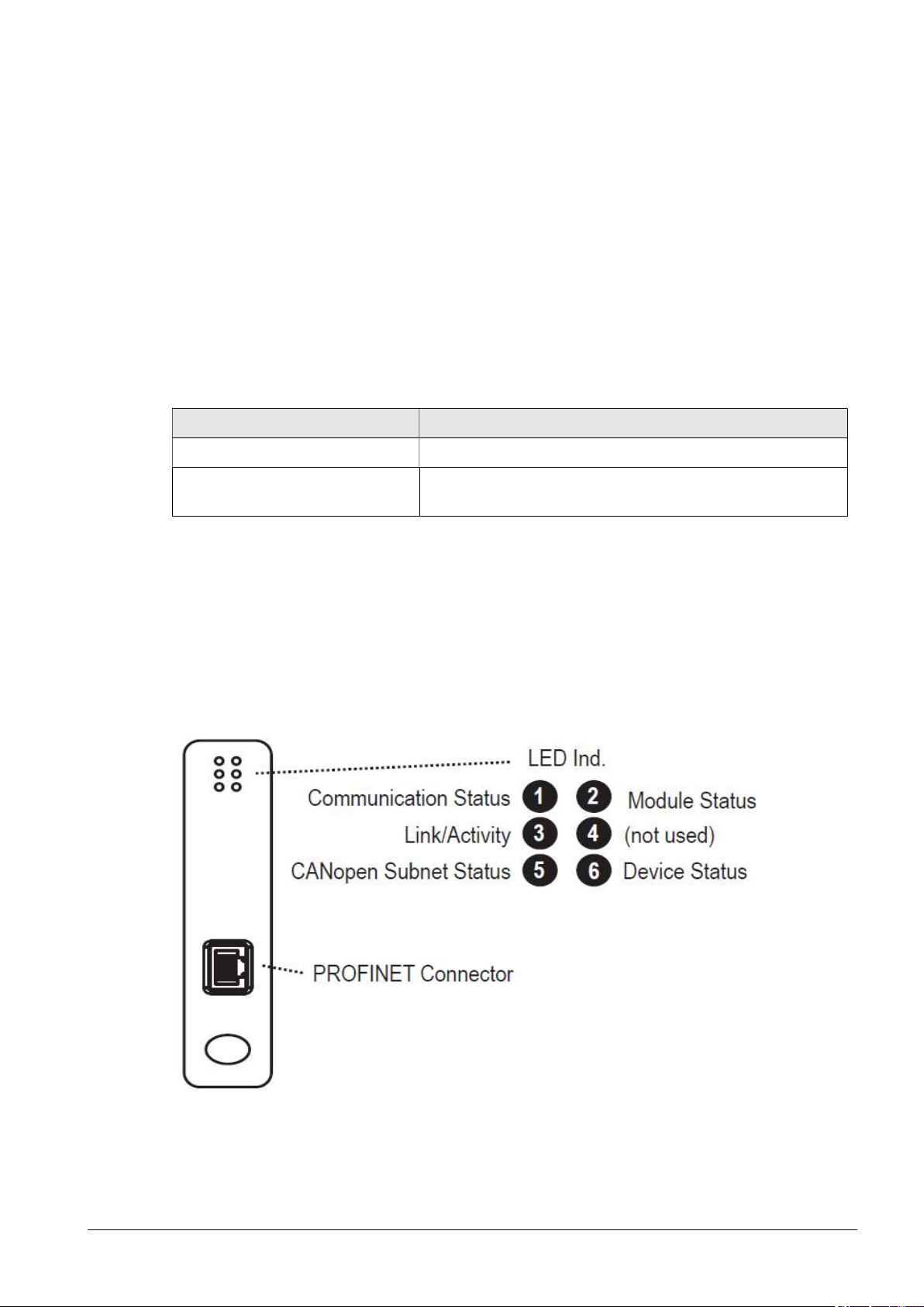
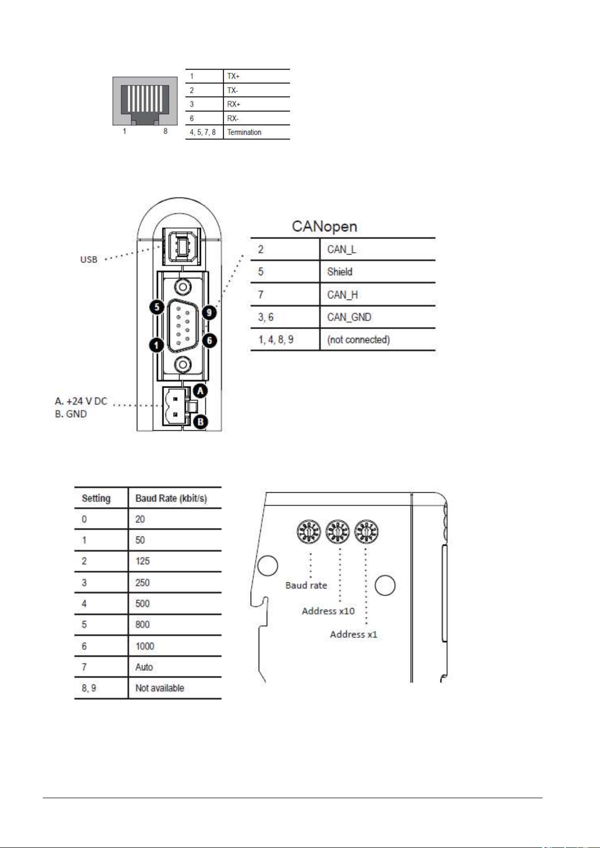
2.3 Connection assignments ................................................................................................................... 7
2.3.1 Anybus X-gateway control connection assignments .......................................................... 7
3 Technical data ........................................................................................................................... 9
4 Transport/Storage ..................................................................................................................... 9
5 Unpacking and Installation .................................................................................................... 10
5.1 Unpacking ....................................................................................................................................... 10
5.2 Installation requirements ................................................................................................................. 10
5.3 Installation ....................................................................................................................................... 10
6 Operation and configurations ................................................................................................ 12
6.1 Taking into operation ....................................................................................................................... 12
6.2 Anybus X-gateway CANopen Master Configuration ....................................................................... 12
6.3 PS2000 CANopen Slave Konfiguration .......................................................................................... 13
6.4 PDO mapping .................................................................................................................................. 13
6.5 Siemens configuration..................................................................................................................... 14
6.6 Error messages on the Anybus X-gateway..................................................................................... 16
7 Environment ............................................................................................................................ 17
7.1 Disposal .......................................................................................................................................... 17
8 Conformity / Standards .......................................................................................................... 17
8.1 CE ................................................................................................................................................... 17
8.2 Product standards ........................................................................................................................... 17

4 Januar 2023 BA-KommPN_EN / F0354700
1 Safety
The system was designed in accordance with the relevant international standards.
However, as with any technical product, hazards may arise if the system is not used
properly or is used for purposes other than its intended use.
Working with the system can be dangerous and may result in serious or fatal injury. It is
therefore essential to protect yourself and others.
In addition to the safety instructions in this document, you must also comply with general
safety standards.
Caution - Danger!
When working with the system, please note and observe the safety instructions and
requirements in these operating instructions because non-compliance may result in
serious or fatal injury.
1.1 Residual risks
This system has been manufactured in accordance with the current state of the art.
However, it is impossible to eliminate residual risks.
Always adhere to the following safety instructions:
Caution – Electrical voltage!
• Danger: 230 V. If damage is visible on the electrical connection, mains cable or
system:
- Do not start up the system.
- Have the damaged parts repaired by a qualified person or replace them.
Trip hazard!
Lay the connection cables in suitable cable trays. Lay cables such that they do not
present a trip hazard.
1.2 Information and obligations for the operator
• The system may emit interference.
- The system has been tested in accordance with EMC legislation.
- The operator must verify and assure electromagnetic compatibility with other
electrical and electronic equipment in the immediate vicinity of the system.
• Ensure that
- operating personnel have read and understood these operating instructions.
- anyone working near the machine is made aware of the dangers and is provided
with the necessary protective equipment.
- Repairs are only carried out by qualified persons.
• In particular, make operating personnel aware of the safety instructions in this
document.
• Always keep the system in fully functional condition.
• Any modifications made to the machine will invalidate the operating licence and the
warranty unless such modifications are expressly authorised by the manufacturer.

BA-KommPN_EN / F0354700 Januar 2023 5
1.3 Intended use
The system is intended solely for operation with the PS2000 high-voltage source and a
plasma generator from relyon plasma GmbH.
Coupled with a suitable plasma generator, the machine is intended solely for the plasma
treatment of surfaces (metals, textiles, glass, plastics) to activate, clean, coat or remove
residue at atmospheric pressure.
Under no circumstances may the system be used by non-trained persons.
1.4 Impermissible operating conditions
The system must not be operated under the following conditions:
• In explosive (ex) zones
• In areas with severe build-up of dust
• Where there is excessive air humidity (see Technical data, chapter 3)
• Installation heights above 2,000m above Sea Level
• Where there are strong vibrations
Note!
Please also observe the information in the operating instructions of all additional
components connected to the system.

6 Januar 2023 BA-KommPN_EN / F0354700
2 System description
2.1 Function
The components of this system are the basic elements for communicating with a PS2000
current source via Profinet.
2.2 System overview
2.2.1 Description of the components
No.
Component
1 Anybus X-gateway (CANopen Master – PROFINET-IO AB7307-B)
2 CAN cable (length 2m)
3 CAN terminal resistor (sub-D)
4 CAN terminal resistor (RJ45)
5 USB stick with software and documentation
1
2
3
4
5
Figure 1: Scope of delivery

BA-KommPN_EN / F0354700 Januar 2023 7
2.2.2 Scope of delivery
The scope of delivery includes the following components:
• Anybus X-gateway with specific Software by relyon plasma
• CAN cable (length 2m)
• CAN terminal resistor (sub-D)
• CAN terminal resistor (RJ45)
• Manual
• USB stick with software
2.2.3 Other hardware components needed
Depending on the stage of expansion, several additional hardware components are needed
for a functioning overall system. Either recommendations for these or the characteristics
needed are listed below.
Component Description
Voltage supply U = 24 V DC; I ≥ 1 A; to supply the Anybus X-gateway
Wiring material Various cables, top hat rail terminals and bridges
depending on stage of expansion
2.3 Connection assignments
2.3.1 Anybus X-gateway control connection assignments
The following figures show the connection assignment of the converter. On the front of the
Anybus X-gateway (Figure 2) is the network connector for the Profinet. On the lower side
(Figure 4) there are the connections for the supply voltage (+24V DC), the CANopen bus and
a USB interface for programming. On the side of the module (Figure 5) are various
parameters for setting the CANopen network. The allowed node address range is 1 - 127,
the baud rate is pre-set to 500kbit/s and the address (Node-ID) of the module is 1.
Figure 2: Front of the Anybus X-gateway

8 Januar 2023 BA-KommPN_EN / F0354700
Figure 3: Profinet port
Figure 4: Lower side of the Anybus X-gateway
Figure 5: Side of the Anybus X-gateway

BA-KommPN_EN / F0354700 Januar 2023 9
3 Technical data
X-gateway CANopen
Maximum number of Slaves 126
CANopen Connector DSUB9M
Baud rate Up to 1 Mbit/s
I/O data 128 PDOs received/128 PDOs transmitted, 510 bytes IN/OUT
Extras CANopen specifications DS301 v4.0.2
Technical details Standard
Weight 150 g, 0,33 lb
Dimensions (L•W•H) 120 x 75 x 27 mm, 4,72” x 2,95” x 1,06”
Protection class IP20, NEMA 1
Housing material PC-ABS, UL 94
Position for installation any
Mounting DIN rail (35 x 7, 5/15) EN 50022
Electrical properties
Eelectrical connection 24 VDC +/- 10 %
Eelectrical consumption 250 mA
Hardware properties
Voltage protection Yes
Short-circuit protection Yes
Galvanic isolation in the
subnet
Yes
Operating conditions
Temperature -25 - 55 oC, -13 - 131 oF IEC 60068-2-1
IEC 60068-2-2
Humidity < 90 % rel. (non-condensing) IEC 60068-2-30
Installation height < 2000 m
Storage conditions
Temperature -40 - 85 oC, -40 - 185 oF IEC 60068-2-1
IEC 60068-2-2
Humidity < 80 % rel. (non-condensing) IEC 60068-2-30
Electromagnetic emissions
Elektrostatic discharge +/- 4 kV EN 61000-4-2
Electromagnetic HF-fields 10 V/m 80 MHz - 1 GHz
3 V/m 1,4 GHz - 2,0 GHz
1 V/m 2,0 GHz - 2,7 GHz
EN 61000-4-3
Fast transients +/- 1 kV EN 61000-4-4
Overvoltage protection +/- 1 kV EN 61000-4-5
HF-guided interference 10 V/rms EN 61000-4-6
Emissions (at 10 m) 40 dB 30 MHz - 230 MHz
47 dB 30 MHz - 1 GHz
EN 55016-2-3
4 Transport/Storage
• Store the device in a dry place. This protects the device from corrosion of the electrical
contacts.
• Protect the device from dirt and foreign bodies.

10 Januar 2023 BA-KommPN_EN / F0354700
5 Unpacking and Installation
5.1 Unpacking
• Open the packaging carefully. Observe the directional instructions on the packaging.
• Take the components out of the packaging.
5.2 Installation requirements
Before installing the machine, the following must be true:
• The components must be undamaged.
• If installing as a permanent installation or in a building, a suitable switch or circuit
breaker that satisfies national safety requirements (in Germany: VDE 0100) must be
fitted as an upstream all-pole cut-off device that will disconnect the system from the
power supply. This cut-off device should be fitted near the machine and must be easily
accessible to the user. The switch must also be labelled as the cut-off device for the
machine.
• Only a trained electrician may wire the system.
• Observe all installation requirements and safety notices of the additional machines
connected.
5.3 Installation
To install the system, perform the following steps in the order given:
1. Mount the components provided for this purpose on a DIN rail (35 x 7, 5/15) to ensure stable
mounting.
2. Ensure that the Anybus X-gateway and the power source P2000 are without power.
3. Connect the CAN terminating resistor bushing (Sub-D) (#4) to the CAN cable (length 2m)
(#2) and all this to the Anybus X-gateway
Figure 6: Wiring to X-gateway

BA-KommPN_EN / F0354700 Januar 2023 11
4. Connect the CAN cable (length 2m) (#2) to the rear connector of the power source
PS2000 and terminate the CAN bus with the terminating resistor provided for this
purpose, see also the operating manual of the power source PS2000 if applicable. If two
power sources are used, they are connected to each other with another CAN cable.
(Figure 7)
5. Set the node number of the PS2000 to "10" (or "11" for a possible second power source)
(#7).
6. Establish the emergency stop circuit of the PS2000 as well as all other connections of
the additional devices as described in the corresponding operating manuals.
The system is installed.
Address:10
Figure 7: Wiring to PS2000

12 Januar 2023 BA-KommPN_EN / F0354700
6 Operation and configurations
6.1 Taking into operation
To operate the system the following requirements must be met:
• The main switches of the connected power sources PS2000 must be switched on.
• The emergency stop circuit must be connected correctly.
• There must be no error on the PS2000.
• The CAN bus line must be connected, both ends terminated with terminating resistors
and the correct CAN bus address must be set on the power sources.
• The Profinet cable must be connected.
• The power supply oft he Anybus X-gateway must be provided.
• The status LEDs of the Anybus X-gateway must be green.
• The gas supply of the plasma generator must be given.
• All additionally connected devices/components must be connected correctly.
6.2 Anybus X-gateway CANopen Master Configuration
Anybus X-gateway is set as manager in the CANopen network with the following parameters:
The control of the manager and all nodes is monitored with a hearbeat of:
• Producer Interval (ms): 1000ms
• Consuming Node ID/Time Out (ms): 1500ms
Figure 8: CANopen master configuration

BA-KommPN_EN / F0354700 Januar 2023 13
6.3 PS2000 CANopen Slave Konfiguration
PS2000 is set as slave in the CANopen network with the following parameters:
6.4 PDO mapping
Translation of the signals from CANopen to PROFINET is realized with the following PDO
mappings:
In the Master/Slave configuration the first 6 objects of the PDO mapping are to be considered
as outputs and the remaining 10 objects as inputs. These are the data sets:
Output Data Output Data Size Details
Error Status [2000,00] 1 Byte Reset PS2000 [0 / 1]
High Voltage [2030,00] 1 Byte Switch on plasma [0 / 1]
Power Set [2040,00] 1 Byte Setting power level [70 - 100%]
(Default: 100 %)
Frequency Set [2041,00] 1 Word = 2 Byte Setting frequency [40000Hz - 65000Hz]
(Default: 54000Hz)
Voltage Threshold [2042,00] 1 Word = 2 Byte Internal error threshold -Do not change!
(Default: 500 V)
Current Threshold [2043,00] 1 Word = 2 Byte Internal error threshold -Do not change!
(Default: 100 mA)
Total Output Data Size: 9 Byte
Figure 9: CANopen slave configuration
Figure 10: PDO mapping

14 Januar 2023 BA-KommPN_EN / F0354700
Input Data Input Data Size Details
Status Code [2010,00] 1 Byte Status code of PS2000 (4: Plasma off, 7:
Plasma on, 8: Error)
Power Actual [2020,00] 1 Word = 2 Byte Power of PS2000 [0 - 3200W]
Frequency Actual [2021,00] 1 Byte Frequency of PS2000 [40000Hz - 65000Hz]
Voltage RMS Actual [2022,00] 1 Word = 2 Byte Voltage RMS of PS2000 [0 - 1500V]
Current RMS Actual [2023,00] 1 Word = 2 Byte Current RMS of PS2000 [0 - 1000mA]
Temperature 1 [2050,01] 1 Byte Temperature#1
Temperature 2 [2050,02] 1 Byte Temperature#2
Temperature 3 [2050,03] 1 Byte Temperature#3
Temperature 4 [2050,04] 1 Byte Temperature#4
Power-On time [2060,00] 1 Word = 2 Byte Power-On time
Total Input Data Size: 14 Byte
Important!
In a slave/slave configuration, the first 6 objects of the PDO mapping are to be
considered as inputs and the remaining 10 as outputs.
6.5 Siemens configuration
The Input Data Size and Output Data Size are required in the Siemens configuration to
map the data networks. A correct Siemens configuration looks like this:
Figure 11: Siemens configuration

BA-KommPN_EN / F0354700 Januar 2023 15
Figure 12: Variable configuration
More information about a Siemens integration and configuration can be found in the supplied
documentation “User Manual: Anybus X-gateway CANopen PROFINET“.

16 Januar 2023 BA-KommPN_EN / F0354700
6.6 Error messages on the Anybus X-gateway
The following table shows the possible status of the LEDs on the converter and serves as a
possible assistance. In the figure on the right, the six LEDs are marked with a respective
allocation number.
Figure 12: Error messages on the Anybus X-gateway

BA-KommPN_EN / F0354700 Januar 2023 17
7 Environment
7.1 Disposal
Consider the environment.
Used electrical and electronic equipment must not be disposed of along with normal waste.
- The devices contain valuable materials that can be recycled. Take the device to a
suitable collection point.
8 Conformity / Standards
8.1 CE
We declare CE-conformity.
The marking can be found on the type plate on the back of the device housing.
8.2 Product standards
The device complies with the following regulations and standards:
2014/30/EU
EMC Directive (Electromagnetic Compatibility)
2011/65/EU
RoHS Directive with amendment 2015/863
EN 61000-6-4 (2007) + Al (2011)
Emission standard for industrial environment
EN 61000-6-2 (2005)
lmmunity for industrial environment
EN 55016-2-3, Class A (2017)
EN 55032, Class A (2012)
EN 61000-4-2 (2009)
EN 61000-4-3 (2006) + Al (2008) + A2 (2010)
EN 61000-4-4 (2012)
EN 61000-4-5 (2014) + Al (2018)
EN 61000-4-6 (2014)
relyon plasma GmbH
Osterhofener Str. 6
93055 Regensburg
Germany
Tel.: +49-941-60098-0
Fax: +49-941-60098-100
E-Mail: info@relyon-plasma.com
www.relyon-plasma.com

18 Januar 2023 BA-KommPN_EN / F0354700
Other manuals for Brush
1
Table of contents
Other Relyon plasma Conference System manuals