ADF Web HD67044-B2-20 User manual

Industrial Electronic Devices
ADFweb.com Srl – IT31010 – Mareno – Treviso INFO: www.adfweb.com hone +39.0438.30.91.31
User Manual
M
-
Bus Master / Modbus TCP Slave
Document code: MN67044_ENG Revision 2.00 Page of 30
User Manual
Revision 2.00
English
M-Bus Master / Modbus TCP Slave -
Converter
(Order Code: HD67044-B2-20, HD67044-B2-40,
HD67044-B2-80, HD67044-B2- 60,
HD67044-B2-250)
for Website information:
www.adfweb.com?Product=HD67044-B2
for Price information:
www.adfweb.com?Price=HD67044-B2-20
www.adfweb.com?Price=HD67044-B2-40
www.adfweb.com?Price=HD67044-B2-80
www.adfweb.com?Price=HD67044-B2- 60
www.adfweb.com?Price=HD67044-B2-250
Benefits and Main Features:
Very easy to configure
Up to 250 standard M-Bus devices connected to
the Converter
Power Supply 5…2 V AC or 8…35V DC
Industrial temperature range:
-40°C / 85°C (-40°F / 85°F)
Similiar
Products
For other M-Bus products see also the following link:
Converter - M-Bus /
www.adfweb.com?Product=HD6702 (RS232)
www.adfweb.com?Product=HD67022 (RS4 5)
www.adfweb.com?Product=HD67030 (Ethernet)
Analyzer & Scanner M-Bus
www.adfweb.com?Product=HD6703
M-Bus – Repeater - Isolator
www.adfweb.com?Product=HD67032
Converter - M-Bus Master/ Modbus Slave
www.adfweb.com?Product=HD67029M-232 (on RS232)
www.adfweb.com?Product=HD67029M-485 (on RS4 5)
M-Bus Master / PROFIBUS Slave - Converter
www.adfweb.com?Product=HD67053M
M-Bus – Concentrator - Datalogger
www.adfweb.com?Product=HD67054M
M-Bus Slave / Modbus Master - Converter
www.adfweb.com?Product=HD67059M-232
Do you need to choose a device? do you want help?
Ask it to the following link: www.adfweb.com?Cmd=helpme
HD67044
-
B2
Industrial Electronic Devices
ADFweb.com Srl – IT31010 – Mareno – Treviso INFO: www.adfweb.com hone +39.0438.30.91.31
User Manual
M
-
Bus Master / Modbus TCP Slave
Document code: MN67044_ENG Revision 2.00 Page 2 of 30
INDEX:
Page
INDEX 2
UPDATED DOCUMENTATION 2
REVISION LIST 2
WARNING 2
TRADEMARKS 2
SECURITY ALERT 3
EXAMPLE OF CONNECTION 4
CONNECTION SCHEME 5
CHARACTERISTICS 6
POWER SUPPLY 7
FUNCTION MODES 8
LEDS 9
MODBUS TCP 0
M-BUS 0
USE OF COMPOSITOR SW67044
NEW PROJECT / OPEN PROJECT
SET COMMUNICATION 2
M-BUS 3
UPDATE DEVICE (ONLY FOR HD67044-B2 SERIES) 25
MECHANICAL DIMENSIONS 27
ORDER CODES 28
ACCESSORIES 28
DISCLAIMER 29
OTHER REGULATIONS AND STANDARDS 29
WARRANTIES AND TECHNICAL SUPPORT 30
RETURN POLICY 30
PRODUCTS AND RELATED DOCUMENTS 30
UPDATED DOCUMENTATION:
Dear customer, we thank you for your attention and we remind you that you
need to check that the following document is:
Updated
Related to the product you own
To obtain the most recently updated document, note the “document code” that
appears at the top right-hand corner of each page of this document.
With this “Document Code” go to web page www.adfweb.com/download/ and
search for the corresponding code on the page. Click on the proper “Document
Code” and download the updates.
To obtain the updated documentation for the product that you own, note the
“Document Code” (Abbreviated written "Doc. Code" on the label on the product)
and download the updated from our web site www.adfweb.com/download/
REVISION LIST:
WARNING:
ADFweb.com reserves the right to change information in this manual about our
product without warning.
ADFweb.com is not responsible for any error this manual may contain.
TRADEMARKS:
All trademarks mentioned in this document belong to their respective owners.
Revision
Date Author Chapter
Description
.020 30/03/20 0
Ft All Revision
.02 22/ 0/20 0
Fl All Revision
.030 04/03/20
Fl All Software changed (v .300)
2.000 03/ 2/20 2
Fl All New hardware version
2.00 29/03/20 3
Fl All Added new chapters

Industrial Electronic Devices
ADFweb.com Srl – IT31010 – Mareno – Treviso INFO: www.adfweb.com hone +39.0438.30.91.31
User Manual
M
-
Bus Master / Modbus TCP Slave
Document code: MN67044_ENG Revision 2.00 Page 3 of 30
SECURITY ALERT:
G
ENERAL
I
NFORMATION
To ensure safe operation, the device must be operated according to the instructions in the manual. When using the device are required for
each individual application, legal and safety regulation. The same applies also when using accessories.
I
NTENDED
U
SE
Machines and systems must be designed so the faulty conditions do not lead to a dangerous situation for the operator (i.e. independent limit
switches, mechanical interlocks, etc.).
Q
UALIFIED
P
ERSONNEL
The device can be used only by qualified personnel, strictly in accordance with the specifications.
Qualified personnel are persons who are familiar with the installation, assembly, commissioning and operation of this equipment and who
have appropriate qualifications for their job.
R
ESIDUAL
R
ISKS
The device is state of the art and is safe. The instrument can represent a potential hazard if they are inappropriately installed and operated
by personnel untrained. These instructions refer to residual risks with the following symbol:
This symbol indicates that non-observance of the safety instructions is danger for people to serious injury or death and / or the
possibility of damage.
CE
CONFORMITY
The declaration is made by us. You can send an email to support@adfweb.com or give us a call if you need it.

Industrial Electronic Devices
ADFweb.com Srl – IT31010 – Mareno – Treviso INFO: www.adfweb.com hone +39.0438.30.91.31
User Manual
M
-
Bus Master / Modbus TCP Slave
Document code: MN67044_ENG Revision 2.00 Page 4 of 30
EXAMPLE OF CONNECTION:

Industrial Electronic Devices
ADFweb.com Srl – IT31010 – Mareno – Treviso INFO: www.adfweb.com hone +39.0438.30.91.31
User Manual
M
-
Bus Master / Modbus TCP Slave
Document code: MN67044_ENG Revision 2.00 Page 5 of 30
CONNECTION SCHEME:
Figure
1
: Connection scheme for HD670
44
-
B2
-
xxx

Industrial Electronic Devices
ADFweb.com Srl – IT31010 – Mareno – Treviso INFO: www.adfweb.com hone +39.0438.30.91.31
User Manual
M
-
Bus Master / Modbus TCP Slave
Document code: MN67044_ENG Revision 2.00 Page 6 of 30
CHARACTERISTICS:
The HD67044-B2-xxx is a M-Bus Master / Modbus TCP Slave Converter.
It allows the following characteristics:
Electrical isolation between Ethernet and M-Bus;
Mountable on 35mm Rail DIN;
Power Supply 5…2 V AC or 8…35V DC;
Temperature range -40°C to 85°C.
At the Converter can be connected up to 250 standard M-Bus devices. This number depends of the code expressed by the xxx number:
HD67044-B2-20 support up to 20 M-Bus devices;
HD67044-B2-40 support up to 40 M-Bus devices;
HD67044-B2-80 support up to 80 M-Bus devices;
HD67044-B2- 60 support up to 60 M-Bus devices;
HD67044-B2-250 support up to 250 M-Bus devices.
In the case of HD67044-B2- 60 the device must be mounted on 35mm DIN rail which is horizontally mounted on a wall or cabinet
back-plate. To avoid obstructions to the airflow around the unit it is recommended to not cover the paths of air.
In the case of HD67044-B2-250 the device must be mounted on 35mm DIN rail which is horizontally mounted on a wall or cabinet
back-plate. These units have a fan in the top of the enclosure. To avoid obstructions to the airflow around the unit it is recommended
to not cover the paths of air. Take care to not cover the fan. It is recommended to put the device into a ventilated cabinet.

Industrial Electronic Devices
ADFweb.com Srl – IT31010 – Mareno – Treviso INFO: www.adfweb.com hone +39.0438.30.91.31
User Manual
M
-
Bus Master / Modbus TCP Slave
Document code: MN67044_ENG Revision 2.00 Page 7 of 30
POWER SUPPLY:
The devices can be powered at 5…2 V AC and 8…35V DC. The consumption depends to the code of the device. For more details see the
two tables below.
VAC
VDC
Vmin Vmax Vmin Vmax
15V 21V 1 V 35V
Consumption at 24V DC:
Device No Load [W/VA] Full Load [W/VA]*
HD67044-B2-20
3.5
4
HD67044-B2-40 5
HD67044-B2-80 8
HD67044-B2- 60 4
HD67044-B2-250 30
* This value is with all the Slave M-Bus devices of the code (20, 40, 80, 60, 250) connected to the line
HD670
44
-
B2
-
xxx
Caution
: Not reverse the polarity power
Industrial Electronic Devices
ADFweb.com Srl – IT31010 – Mareno – Treviso INFO: www.adfweb.com hone +39.0438.30.91.31
User Manual
M
-
Bus Master / Modbus TCP Slave
Document code: MN67044_ENG Revision 2.00 Page 8 of 30
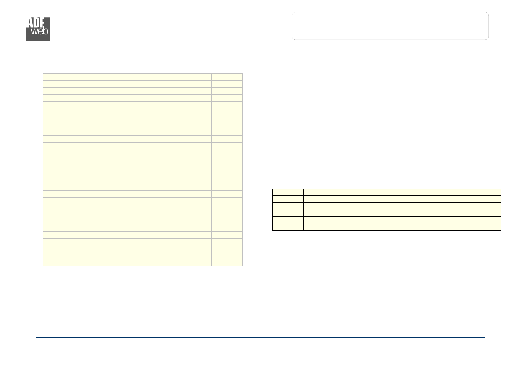
FUNCTION MODES:
The device has got two functions mode depending of the position of the ‘Dip of Dip-Switch A’:
The first, with ‘Dip of Dip-Switch A’ at “OFF” position, is used for the normal working of the device.
The second, with ‘Dip of Dip-Switch A’ at “ON” position, is used for upload the Project and/or Firmware.
For the operations to follow for the updating, see ‘UPDATE DEVICE’ section.
According to the functioning mode, the LEDs will have specifics functions, see ‘LEDS’ section.
Warning:
Dip2 of ‘Dip-Switch A’ must be at ON position for working even if the Ethernet cable isn’t inserted.

Industrial Electronic Devices
ADFweb.com Srl – IT31010 – Mareno – Treviso INFO: www.adfweb.com hone +39.0438.30.91.31
User Manual
M
-
Bus Master / Modbus TCP Slave
Document code: MN67044_ENG Revision 2.00 Page 9 of 30
LEDS:
The device has got two LEDs that are used to give information of the functioning status.
The various meanings of the LEDs are described in the table below.
LED Normal Mode Boot Mode
: Device State (green) Blinks slowly (~ Hz) Blinks quickly
2: M-Bus Comm. Blinks quickly when a reply to a M-
Bus request arrives Blinks quickly
3: M-Bus Error Becames ON when the reply to M-
Bus interrogation isn’t arrived Blinks quickly
4: Modbus Comm. Changes state when receive a
correct Modbus request Blinks quickly
5: Ethernet Link (green) ON: Ethernet cable connected
OFF: Ethernet cable disconnected
ON: Ethernet cable connected
OFF: Ethernet cable disconnected
Industrial Electronic Devices
ADFweb.com Srl – IT31010 – Mareno – Treviso INFO: www.adfweb.com hone +39.0438.30.91.31
User Manual
M
-
Bus Master / Modbus TCP Slave
Document code: MN67044_ENG Revision 2.00 Page 0 of 30
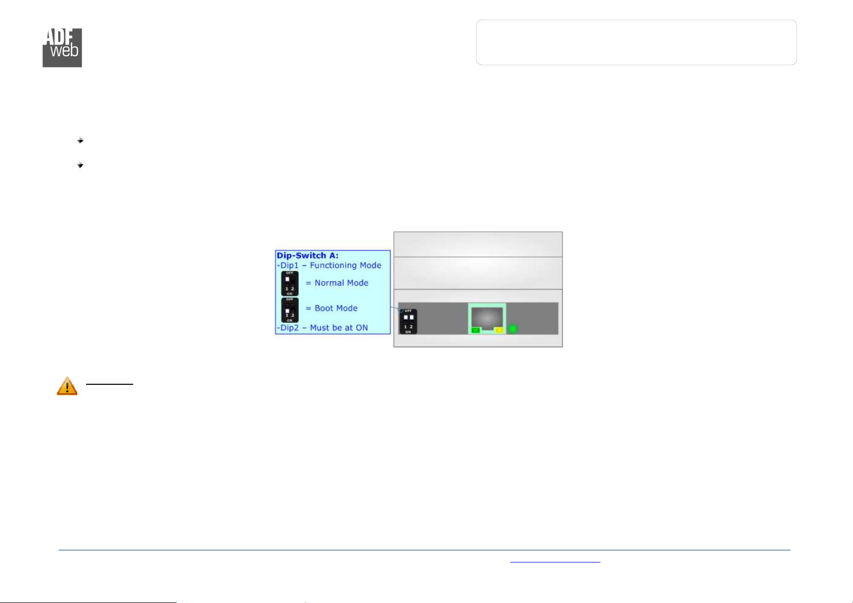
MODBUS TCP :
The Modbus TCP connection must be made using Connector3 of HD67044-B2 with at least a Category 5E
cable. The maximum length of the cable should not exceed 00m. The cable has to conform to the T568
norms relative to connections in cat.5 up to 00 Mbps. To connect the device to an Hub/Switch is
recommended the use of a straight cable, to connect the device to a PC/PLC/other is recommended the
use of a cross cable.
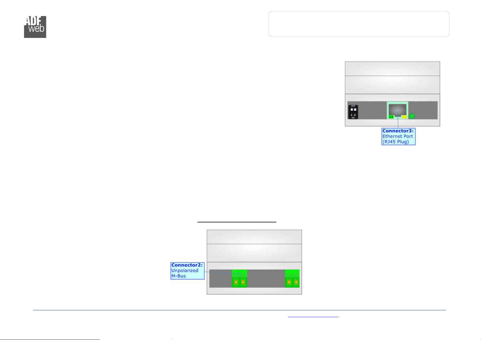
M-BUS:
The M-Bus is a unpolarized bus.
A two wire standard telephone cable (JYStY N*2*0.8 mm) is used as the transmission medium for the M-Bus. The maximum distance
between a slave and the repeater is 350m; this length corresponds to a cable resistance of up 29Ω. This distance applies for the standard
configuration having Baud rates between 300 and 9600 Baud, and a maximum of 250 slaves. The maximum distance can be increased by
limiting the Baud rate and using fewer slaves, but the bus voltage in the space state must at no point in a segment fall below 2V, because
of the remote powering of the slaves. In the standard configuration the total cable length should not exceed 000m, in order to meet the
requirement of a maximum cable capacitance of 80nF. (Taken from M-Bus specifics)

Industrial Electronic Devices
ADFweb.com Srl – IT31010 – Mareno – Treviso INFO: www.adfweb.com hone +39.0438.30.91.31
User Manual
M
-
Bus Master / Modbus TCP Slave
Document code: MN67044_ENG Revision 2.00 Page of 30
USE OF COMPOSITOR SW67044:
To configure the Converter, use the available software that runs with
Windows, called SW67044. It is downloadable on the site
www.adfweb.com and its operation is described in this document.
(This manual is referenced to the last version of the software present
on our web site). The software works with MSWindows (MS 2000, XP,
Vista, Seven, 8; 32/64bit).
When launching the SW67044 the right window appears (Fig. 2).
Note:
It is necessary to have installed .Net Framework 4.
NEW PROJECT / OPEN PROJECT:
The “New Project” button creates the folder which contains the entire device configuration.
A device configuration can also be imported or exported:
To clone the configurations of a Programmable “M-Bus / Modbus TCP – Converter” in order
to configure another device in the same manner, it is necessary to maintain the folder and
all its contents;
To clone a project in order to obtain a different version of the project, it is sufficient to
duplicate the project folder with another name and open the new folder with the button
“Open Project”.
Figure
2
:
Main window
for
SW
670
4
4

Industrial Electronic Devices
ADFweb.com Srl – IT31010 – Mareno – Treviso INFO: www.adfweb.com hone +39.0438.30.91.31
User Manual
M
-
Bus Master / Modbus TCP Slave
Document code: MN67044_ENG Revision 2.00 Page 2 of 30
SET COMMUNICATION:
This section define the fundamental communication parameters of two Buses, Modbus and M-Bus.
By Pressing the “Set Communication” button from the main window for SW67044 (Fig. 2) the window
“Set Communication” appears (Fig. 3).
The window is divided in three sections, the first used for select the device, one for the Modbus TCP
(Ethernet) and the other for the M-Bus.
The means of the fields for Select Device are:
If the hardware in your possession is the HD67044M-xxx you have to select “HD67044M”;
otherwise if the hardware in your possess is the HD67044-B2-xxx you have to select “HD67044-
B2”.
The means of the fields for Ethernet are:
In the field “IP Address” insert the IP address of the device;
In the field “Subnet Mask” insert the Subnet Mask;
If the field “Gateway” is checked it is possible to insert, in the field under, the IP Address of the
Converter used for going out to the net;
In the field “TCP Port” insert the number of the port used for communicate.
The means of the fields for M-Bus are:
In the field “Baudrate” it is possible to select the baudrate of the M-Bus line;
In the field “Parity” it is possible to select the parity of the line;
If the field “M-Bus Poll on request” is checked, the Converter makes the request only if a Modbus
register is requested; otherwise if “Cyclic request” is checked, the Converter makes the request in
M-bus network each time the time defined under passes;
In the field “Delay” insert a time expressed in seconds. This time is used for the “Cyclic request”;
In the field “Node State value when slave device is not present” it is possible to insert the
value to assign to the “Node State” when the Converter doesn’t find the interrogated slave M-Bus. Figure 3: “Set Communication”
window

Industrial Electronic Devices
ADFweb.com Srl – IT31010 – Mareno – Treviso INFO: www.adfweb.com hone +39.0438.30.91.31
User Manual
M
-
Bus Master / Modbus TCP Slave
Document code: MN67044_ENG Revision 2.00 Page 3 of 30
M-BUS
By Pressing the “M-Bus” button from the main window for SW67044 (Fig. 2) the window “M-Bus Network” appears (Fig. 4).
S
ECTION
N
ODES
:
In the section “Nodes” it is possible to create the nodes of M-Bus
line. In order to create a new node it is necessary to select which
address use, selecting “Primary ID” or “Secondary ID”, to makes
the requests and then insert the “Primary Address” (from to 250)
or the Secondary Address” (from 0 to 99999999) of M-Bus device in
the field “ID Node M-Bus”. In the field “Description” it is possible
to write a short description of the node.
In the field “Node State” it is possible to insert an address Modbus
that contain the Status of the M-Bus device. If you don’t need to
know this, put this register at 0.
In the field “Identification Number” it is possible to insert an
address Modbus that contain the Identification Number of the M-Bus
device. You have to read two consecutive registers for knowing the
value. If you don’t need to know this, put this register at 0.
If the field “Convert BCD in Integer Identification Num.” is
checked the Converter converts the Identification Number that is
normally expressed in BCD in a Integer.
In the field “Swap Identification Num.” it is possible to select the
swap mode of the Identification Number. If swap isn’t necessary you
have to select “None”; otherwise see the section “Swap
Identification” (page 20) of this document for select the swap mode.
If the field “Send SND_NKE” is checked, the Converter send the
“SND_NKE” frame to start the communication.
In the field “Send Reset App.” Is checked the Converter send the
“Application Reset” command to the slave. In the field “Variables
List” it is possible to select which type of variables definition to use.
If is selected “By Type” it is necessary to fill all fields, in the section
Variables, with the correct values; otherwise if “By Position” is selected you can insert the progressive number of the variable that you need
(page 8 for more information).
After that, pressing the “ADD NODE” button, a new node appears in the left side of the window. In order to modify a created node it is
necessary to select the desired node, change the wrong items and then press the “MODIFY NODE” button.
Figure
4:
“M
-
Bus Network” window

Industrial Electronic Devices
ADFweb.com Srl – IT31010 – Mareno – Treviso INFO: www.adfweb.com hone +39.0438.30.91.31
User Manual
M
-
Bus Master / Modbus TCP Slave
Document code: MN67044_ENG Revision 2.00 Page 4 of 30
S
ECTION
V
ARIABLES
(B
Y
T
YPE
):
Selecting the desired node it is possible to add a variable. In order
to create a new variable it is necessary to fill these items:
To use the created variable the field “Enable Variable”
must be checked. If you have created a variable but for the
moment it is unused it is possible to uncheck the field
“Enable Variable” without delete it;
In the field “Description” it is possible to write a
description of the variable (it isn’t a necessary information,
it helps the readability of the tree of network);
The field “Type of Data” is used to select the unit of
measure;
In the field “VIF ASCII String” insert the string of VIF. It
is possible to use this field only if the “Type of Data” is “VIF
is in ASCII”;
In the field “Function Field” it is necessary to select the
type of data;
The field “Dimension” is used to select the dimension of
the variable (8, 6, 24, 32, 32 real, 48, 64 bit, Variable
Length);
In the field “Length(Variable Len)” insert the length of
the data in the case of the dimension is “Variable Length”;
In the field “Unit” if it is necessary it is possible to select
the unit of that variable. The Unit is used for indicates from
which device the data come;
In the field “Modbus Register” it is necessary to insert the
value of Modbus Register that contains the data of the M-Bus device. It is possible to insert from Modbus Register “ ” to “60000”;
In the field “Modbus Re Scale” it is necessary to insert the value of Modbus Register that contains the value of measure scale. If the
scale is not necessary, you have to insert the number “0” in this field. It is possible to insert from Modbus Register “ ” to “60000”;
In the field “Storage Number” if it is necessary it is possible to insert the value of storage counter of that variable. With this field
the slave can indicate and transmit various stored counter states or historical values, in the order in which they occur;
In the field “Tariff” if it is necessary it is possible to insert the value of the tariff of that variable. The Tariff is used for indicates from
which device the data come;
In the field “VIFE” it is possible to select a sub-type of “Type of Data”;

Industrial Electronic Devices
ADFweb.com Srl – IT31010 – Mareno – Treviso INFO: www.adfweb.com hone +39.0438.30.91.31
User Manual
M
-
Bus Master / Modbus TCP Slave
Document code: MN67044_ENG Revision 2.00 Page 5 of 30
If the field “Use Five Modbus Register” and the “Type of Data” is “Time Point” it is possible to read the information of Year, Month,
Day, Hour, Minutes on five consecutive Modbus registers without decoding the data (if not selected the values are the same of the
reply of the slave device, so coded with a determinate structure). You have to insert the first Modbus Register.
If the field “From BCD to Integer” is checked the Converter converts the BCD value of variable in Integer format. This happens only
if the variable is in BCD format; if it isn’t nothing changes.
If the field “Convert in Float” is checked the Converter converts the data into Float type. Every variable occupies two consecutive
Modbus Registers and the first one is the one defined in “Modbus Register”. In this case the float value is multiplied by the “Modbus
Re Scale” automatically.
Having completed this fields, to add the variable the button “ADD VARIABLE” must be pressed.
In order to modify a created variable it is necessary to select the desired variable, change the wrong items and then press the “MODIFY
VARIABLE” button.

Industrial Electronic Devices
ADFweb.com Srl – IT31010 – Mareno – Treviso INFO: www.adfweb.com hone +39.0438.30.91.31
User Manual
M
-
Bus Master / Modbus TCP Slave
Document code: MN67044_ENG Revision 2.00 Page 6 of 30
SECTION VARIABLES (BY POSITION):
Selecting the desired node it is possible to add a variable. In order
to create a new variable it is necessary to fill these items:
To use the created variable the field “Enable Variable”
must be checked. If you have created a variable but for the
moment it is unused it is possible to uncheck the field
“Enable Variable” without delete it;
In the field “Description” it is possible to write a
description of the variable (it isn’t a necessary information,
it helps the readability of the tree of network);
The field “Dimension” is used to select the dimension of
the variable (8, 6, 24, 32, 32 real, 48, 64 bit, Variable
Length);
In the field “Length(Variable Len)” insert the length of
the data in the case of the dimension is “Variable Length”;
In the field “Modbus Register” it is necessary to insert the
value of Modbus Register that contains the data of the M-
Bus device. It is possible to insert from Modbus Register
“ ” to “60000”;
In the field “Modbus Re Scale” it is necessary to insert the
value of Modbus Register that contains the value of
measure scale. If the scale is not necessary, you have to
insert the number “0” in this field. It is possible to insert
from Modbus Register “ ” to “60000”;
If the field “Use Five Modbus Register” and the “Type of
Data” is “Time Point” it is possible to read the information of Year, Month, Day, Hour, Minutes on five consecutive Modbus registers
without decoding the data (if not selected the values are the same of the reply of the slave device, so coded with a determinate
structure (page 25 for more information)). You have to insert the first Modbus Register.
If the field “From BCD to Integer” is checked the Converter converts the BCD value of variable in Integer format. This happens only
if the variable is in BCD format; if it isn’t nothing changes;
If the field “SWAP” is checked the byte of data of that variable are swapped. Example: from 0x0 020304 to 0x0403020 ;
In the field “Position” insert the number of the variable that you want on Modbus.

Industrial Electronic Devices
ADFweb.com Srl – IT31010 – Mareno – Treviso INFO: www.adfweb.com hone +39.0438.30.91.31
User Manual
M
-
Bus Master / Modbus TCP Slave
Document code: MN67044_ENG Revision 2.00 Page 7 of 30
Example:
0x68 - Start Byte
0xBD - L Fied
0xBD - L Field
0x68 - Start Byte
0x08 - C Field
0x02 - A Field
0x72 - CI Field
0x7 - Identification Number (Byte 4of4)
0x65 - Identification Number (Byte 3of4)
0x45 - Identification Number (Byte 2of4)
0x28 - Identification Number (Byte of4)
0x4D - Manufacturer (Byte 2of2)
0x6A - Manufacturer (Byte of2)
0x8 - Version
0x04 - Medium
0x3E - Access Number
0x27 - Status
0x00 - Signature (Byte 2of2)
0x00 - Signature (Byte of2)
0x04 - DIF
0x79 - VIF Identification
0x00 - Data (Byte 4of4)
0x00 - Data (Byte 3of4)
0x00 - Data (Byte 2of4)
0x00 - Data (Byte of4)
0x04 - DIF
0x06 - VIF Energy
0x00 - Data (Byte 4of4)
0x00 - Data (Byte 3of4)
0x00 - Data (Byte 2of4)
0x00 - Data (Byte of4)
0x44 - DIF
0x06 - VIF Energy
0x00 - Data (Byte 4Of4)
0x00 - Data (Byte 3Of4)
0x00 - Data (Byte 2Of4)
0x00 - Data (Byte Of4)
…
… Other Variables
…
0x55 - Check Sum
0x 6 - Stop Byte
Fixed Data Header
First Variable ( )
Second Variable ( 2 )
Third Variable ( 3 )
To be use in the “Position” field
Identification Number (or Secondary Address) putted in
the selected register if “Identification Number” is
checked
Status of the meter putted in the selected register if
“Node State” is checked

Industrial Electronic Devices
ADFweb.com Srl – IT31010 – Mareno – Treviso INFO: www.adfweb.com hone +39.0438.30.91.31
User Manual
M
-
Bus Master / Modbus TCP Slave
Document code: MN67044_ENG Revision 2.00 Page 8 of 30
S
ECTION
D
ELETE
I
TEMS
:
If it is necessary to delete a node or a variable, you have to select
the node or the variable and then press the “DELETE ITEM”
button.

Industrial Electronic Devices
ADFweb.com Srl – IT31010 – Mareno – Treviso INFO: www.adfweb.com hone +39.0438.30.91.31
User Manual
M
-
Bus Master / Modbus TCP Slave
Document code: MN67044_ENG Revision 2.00 Page 9 of 30
Possible choices for the fields used to create a variable:
Type of Data:
|_Energy (Wh)
|_Energy (J)
|_Volume (m
3
)
|_Mass (Kg)
|_On Time
|_Operating Time
|_Power (W)
|_Power (J/h)
|_Volume Flow (m
3
/h)
|_Volume Flow Ext. (m
3
/min)
|_Volume Flow Ext. (m
3
/s)
|_Mass Flow (Kg/h)
|_Flow Temperature (°C)
|_Return Temperature (°C)
|_Temperature Difference (K)
|_External Temperature (°C)
|_Pressure (bar)
|_Averaging Duration
|_Actuality Duration
|_Type of data in VIFE
|_Time Point
|_VIF is in ASCII
|_Unit for H.C.A.
|_Fabrication No
|_(Enhaced) Identification
|_Bus Address
Function Field:
|_Instantaneous Value
|_Minimum Value
|_Maximum Value
|_Value During Error State
Dimension (bit):
|_8
|_ 6
|_24
|_32
|_32 real
|_48
|_64
|_Variable Length

Industrial Electronic Devices
ADFweb.com Srl – IT31010 – Mareno – Treviso INFO: www.adfweb.com hone +39.0438.30.91.31
User Manual
M
-
Bus Master / Modbus TCP Slave
Document code: MN67044_ENG Revision 2.00 Page 20 of 30
VIFE:
|_ Not Selected
|_ Credit of the nominal local legal currency units
|_ Debit of the nominal local legal currency units
|_ Access Number (transmission count)
|_ Medium (as in fixed header)
|_ Manufacturer (as in fixed header)
|_ Parameter set identification
|_ Model/Version
|_ Hardware Version #
|_ Firmware Version #
|_ Software Version #
|_ Customer Location
|_ Customer
|_ Access Code User
|_ Access Code Operator
|_ Access Code System Operator
|_ Access Code Developer
|_ Password
|_ Error flags (binary)
|_ Error mask
|_ Digital Output (binary)
|_ Digital Input (binary)
|_ Baudrate [Baud]
|_ response delay time [bittimes]
|_ Retry
|_ First storage # for cyclic storage
|_ Last storage # for cyclic storage
|_ Size of storage block
|_ Storage interval [sec(s)..day(s)]
|_ Storage interval month(s)
|_ Storage interval year(s)
|_ Duration since last readout[sec(s)..day(s)]
|_ Start (date/time) of tariff
|_ Duration of tariff (nn=0 .. :min to day)
|_ Period of tariff [sec(s) to day(s)]
|_ Period of tariff months(s)
|_ Period of tariff year(s)
|_ dimensionless/ no VIF
|_ Volts
|_ Ampere
|_ Reset counter
|_ Comulation counter
|_ Control signal
|_ Day of week
|_ Week number
|_ Time point of day change
|_ State of parameter activation
|_ Special supplier information
|_ Duration since last comulation [hour(s)..year(s)]
|_ Operation time battery [hour(s)..year(s)]
|_ Date and time of battery change
|_ Energy MWh
|_ Energy GJ
|_ Volume
|_ Mass
|_ Volume 0, feet^3
|_ Volume 0, american gallon
|_ Volume american gallon
|_ Volume flow 0,00 american gallon/min
|_ Volume flow american gallon/min
|_ Volume flow american gallon/h
|_ Power MW
|_ Power GJ/h
|_ Flow Temperature
|_ Return Temperature
|_ Temperature Difference
|_ External Temperature
|_ Cold/Warm Temperature Limit °F
|_ Cold/Worm Temperature Limit °C
|_ Cumul. count max power
This manual suits for next models
4
Table of contents
Popular Conference System manuals by other brands

Danish Interpretation Systems
Danish Interpretation Systems DCS 6000 user manual

Prodys
Prodys V-Quantum Hardware and Reference Manual

QNAP
QNAP KoiBox-100W user guide

OneScreen
OneScreen h3-65 unit quick start guide

Panasonic
Panasonic WXT3020 - ORDER TAKER - MULTI LANGUAGE operating instructions

PUAS
PUAS U51VC user manual


