Remaco MIC-801 User manual

Warning
Important Notes:
All products are thoroughly inspected and fully tested operational in factory. We accept no liability whatsoever for any losses due to improper
operation, or any unauthorized alternation.
All trademarks contained in this installation guide are the property of their respective owners.
Installation Guide ( MIC-801 )
CCOPYRIGHTS 1998 REMACO TECHNOLOGIES PTE LTD WEBSITE: WWW.REMACOTECH.COM
MIC
V: 2.0
V+ GN
Inner Board
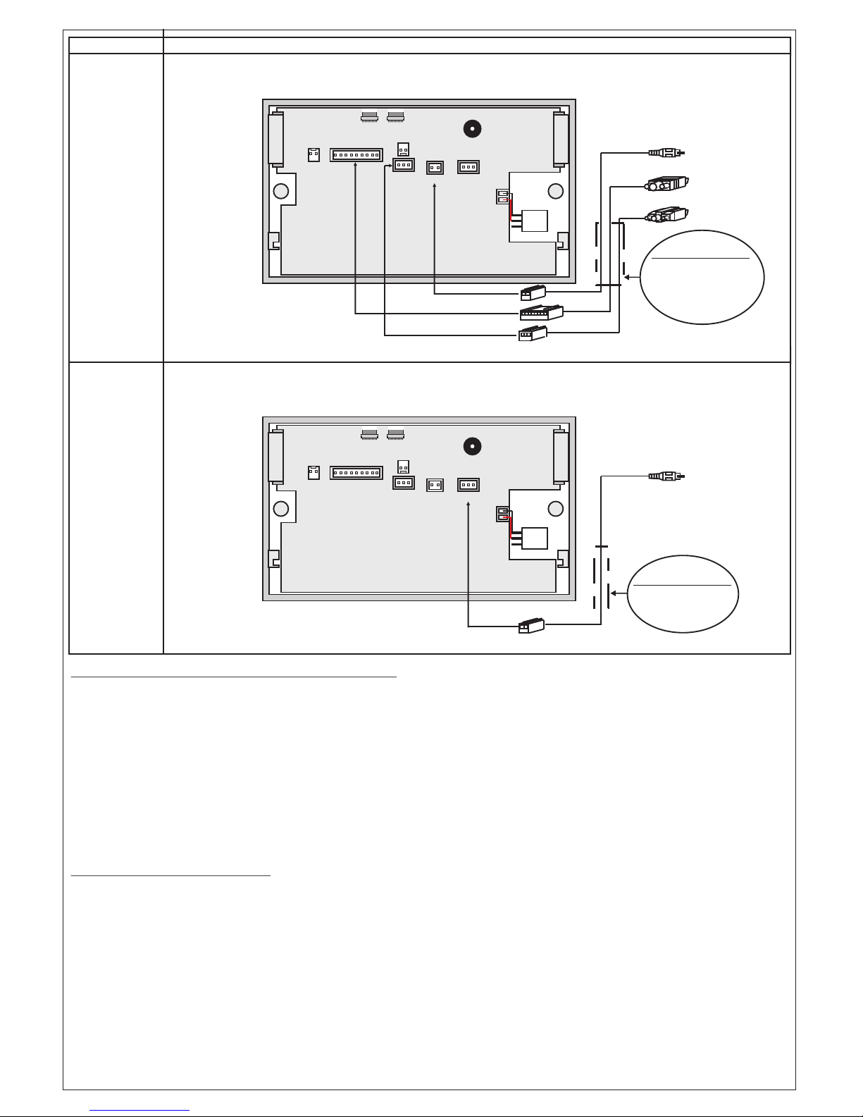
Application
The MIC-801 has 3 D-Sub 15pin input ports for connection to 3 different sources, as well as a video and
microphone input port. All these ports will provide the monitor, speaker and projector output ports with
the desired audio and visual signals that is essential for any classroom or office setups.
Application
Power For connection to a 230V power source
Projector
Monitor
Microphone Player
Speakers
Item
VGA Monitor
PC 1
PC 3
PC 2
PC 1
PC 3
PC 2
PC 2
AUDIO
PC 3
AUDIO
PROJ
ON/OFF
MIC
ON/OFF ON/OFF
BLANK SOURCE VOL
UP
VOL
DOWN
MUTE
PC 3 IN
PC 1
AUDIO
VIDEO
IN RL IN
AUDIO
MIC
IN
134567
SYNC
PC 2 INPC 1 IN
MONITOR OUT
VIDEO
2
Front Panal
Computer 1 Computer 2 Computer 3
230V AC-DC
Adapter
Concept
The MIC-801, Media Interface Controller, is an electronic controller that can be used to link a variety of
audio-visual equipments in classrooms, training rooms & conference rooms. By using the MIC-801, the
selection of equipment will be just within a touch of a button.
Programming MIC-801 To Control Projector
1) Press and hold both "Blank" and "Auto Sync" togeth er for 2 seconds to enter into programming mode.
“MIC”, “VIDEO” and “BLANK” buttons light up indicate program mode.
2) Enter password 3215, PCs button LED will light up.
3) If not successful, a long beep sound will be heard. Re-do above steps again.
5) Key in projector assigned code as listed (Example: 47 for Panasonic projector)
6) If no button is pressed for 60sec, then the programming mode will be deactivated
** Legend for Buttons: "VGA" = 8
To Program Other Settings
1) Press and hold both "Blank" and "Auto Sync" t ogether for 2 seconds to enter into programming mode.
2) Enter password 1216, PCs button LED will light up.
* to reset as factory default, enter digits " 1 1 " (default input selected is "PC 1")
* to set input of the projector to PC 1, enter digits " 1 2 " (must configure with same projector)
* to set input of the projector to PC 2, enter digits " 1 3 " (must configure with same projector)
V+ GN
Inner Board
AUDIO Audio output for connection to audio equipment
Application
VIDEO
VGA
RS-232
Video outputs and controls for connection to visual/audio equipments
Item
* to disable the buzzer, enter digits " 1 4 "
* to enable the buzzer, enter digits " 1 5 "
* to set device as master controller, enter digits " 1 6 " (must configure with same projector)
* to set device as slave controller, enter digits " 1 7 " (must configure with same projector)
VIDEO
VGA
RS-232
OPTIONAL PART
AVA-255
3-in-1
Video, VGA &
RS-232 Cable
AUDIO
OPTIONAL PART
AVA-258
Audio Cable
GND
V
H
GND
B
GND
G
GND
R
RX
TX
GND
GND
RX
VID
GND
GND
R
L
V+ GN
Inner Board
GND
V
H
GND
B
GND
G
GND
R
RX
TX
GND
GND
RX
VID
GND
GND
R
L

To manually program other projector code not listed through RS232
1) Connect computer to MIC-801 using RS232 Cable.
2) Open the MIC program, select "COM" port then click "Open Port".
3) Select any "Projector Number" from "8 1" to "8 8" and set the right "Projector Baud Rate" given
by projector manufacturer manual.
4) Press and hold both "Blank" and "Auto Sync" together for 2 seconds to enter into programming mode.
5) Enter password PCs button LED will light up.1214,
6) From MIC program, click "Write" icon to transfer the code to the MIC-801 device.
User may click "Read" to view previously set control code as well.
Remarks:
To switch off projector, user has to press and hold "Proj On/Off" button on MIC-801 panel for 2 seconds.
Appendix
1) At Master side, connect TX (from SV6) to Slave side of RX (at SV3) as shown in Black Dotted Line wire.
2) At Master side, connect GND (from SV3) to Slave side of GND (at SV3) as shown in BLACK Solid Line wire.
3) At Slave side, connect SV6 (TX & GND) to projector.
Connect 2 female connector as shown in the RED circle (Fig 1) to the header SV3 & SV6 respectively in
MIC-801 as shown in YELLOW circle (Fig 2).
Master and Slave Configuration (applicable if there are more than two MIC-801 connected)
The other end D-SUB 9pins female connector connect to computer ( RS232 to USB Adaptor may require
if computer does not have RS232 port)
Fig-1(RED)
Fig-2(YELLOW)
RS232 Connection Details
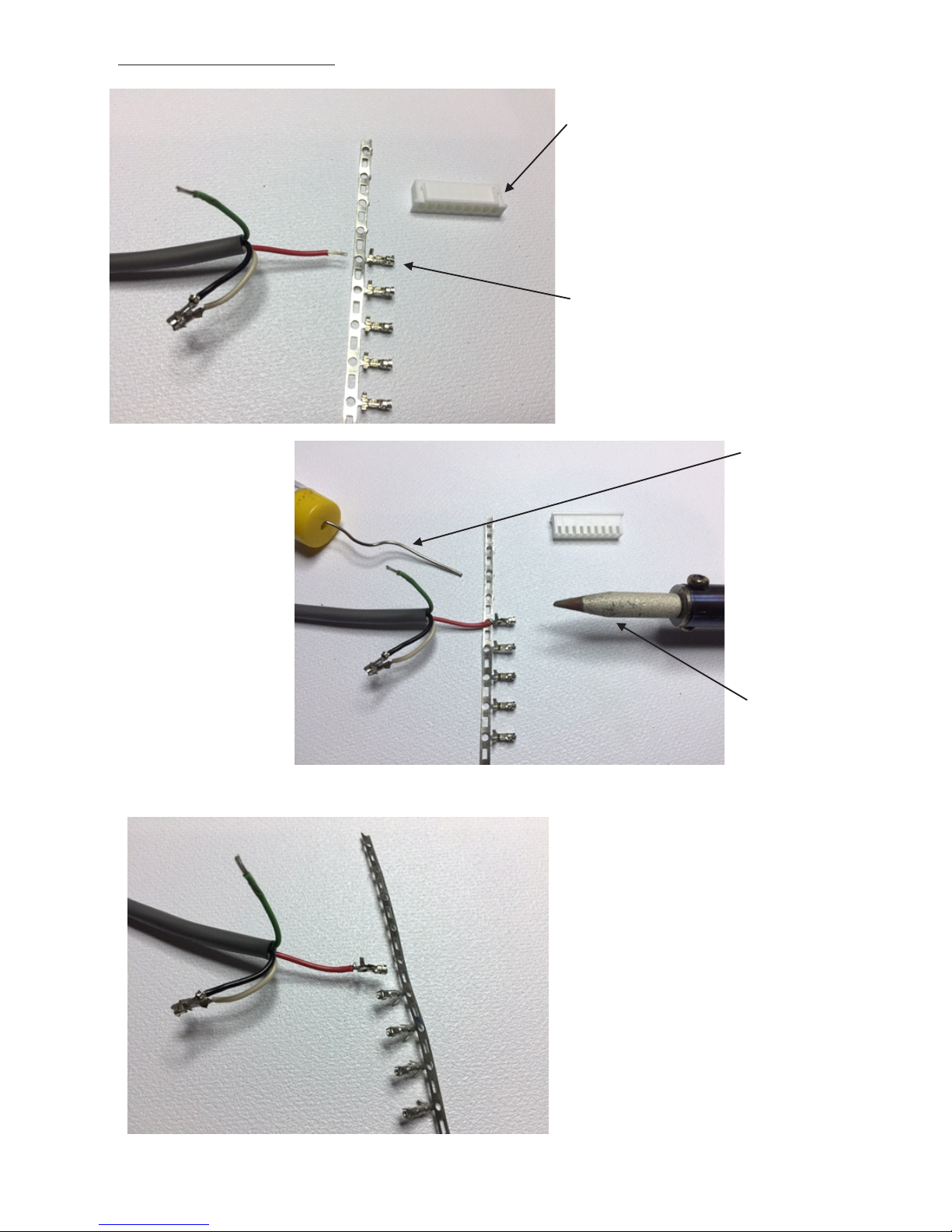
Assembly of XH Connector
XH Housing(Connector)
XH Wafer (Connector Pin)
Step1 - Get ready to solder wire to
XH wafer
Solder Lead
Solder Iron
Step2 - Solder the wire to wafer as shown
Step3 - Bend and break the wafer from others

Step4 - Form the Wafer as shown using Crimper
Step5 - Insert the wafer into the housing
Crimper for XH Connector
Step6 - Repeat above steps for the rest of wafer Assembled XH Connector

Projector Assigned Code Listing
Projector Brand Projector Model Baudrate
3M X SERIES 19200
3M DX SERIES 9600
ACER PH730, PD726, P7500, X1120H, X1220H, X1320H 9600
ACER OLD MODEL w/o OKOKOKOKOK 9600
BENQ 721 SERIES 115200
BENQ PB7210, PB7220 19200
BENQ MP / MX SERIES 115200
CANON SX6 SERIES 19200
CANON LV-7390, 8225 19200
CANON LV-7375, 8300, 8310, 8215 19200
CASIO XJ-H / XJ-M / XJ-ST / PJ SERIES 19200
DELL MP 5100 19200
EPSON ALL MODEL 9600
EIKI ALL MODEL LCD 19200
EIKI ALL MODEL DLP 9600
GEHA COMPACT 218 9600
GEHA COMPACT 228 WITH (2 STOP BIT) 9600
HITACHI ALL MODEL 19200
INFOCUS IN11x / IN12x / IN12xST / IN212x / IN3926 SERIES 9600
INFOCUS IN 554X 19200
INFOCUS IN513x SERIES 19200
INFOCUS IN512x / IN513x / IN514x SERIES 19200
INFOCUS IN510x SERIES 19200
INFOCUS IN SP8602 SERIES 115200
INFOCUS IN210x / IN310x / IN318x SERIES 115200
INFOCUS IN102 / IN104 SERIES 115200
INFOCUS IN 211x / IN311x / IN553x SERIES 115200
INFOCUS IN3118HD / SP8600 / SP8604 9600
INFOCUS IN3916 115200
MITSUBISHI ALL MODEL 9600
NEC ALL MODEL 19200
NEC ALL MODEL 38400
OPTOMA 865 / EW556 / EH2060 9600
OPTOMA EP738 9600
OPTOMA EP757 9600
OPTOMA TW8xx / TX7xx / DX / DS 9600
OPTOMA TX 783 WIRELESS 9600
OPTOMA EP771 9600
OPTOMA EP727 WITH (2 STOP BIT) 9600
PANASONIC ALL MODEL 9600
PANASONIC ALL MODEL 19200
PHILIPS ALL MODEL 9600
SANYO ALL MODEL 19200
SHARP ALL MODEL 9600
SONY EX3 SERIES (non-parity) 38400
SONY CX-FX-PX-DX-DW-EX2xx-EW SERIES (even-parity) 38400
TOSHIBA ALL MODEL 9600
TOSHIBA SP MODEL 9600
VIEWSONIC PJL6243 19200
VIEWSONIC PJL9371 19200
VIEWSONIC 558 SERIES 19200
VIEWSONIC PRO8500 19200
VIEWSONIC PRO9500 19200
VIEWSONIC 559 SERIES 19200
VIEWSONIC PRO8300 19200
VIVITEK D5180 / 5185 115200
VIVITEK D85x / D86x / D87x series 9600
VIVITEK D5 SERIES / H SERIES 9600
Assigned
Code
1 1
1 2
1 3
1 4
1 5
1 6
1 7
1 8
4 6
3 6
2 1
2 2
2 3
4 6
4 7
2 4
2 5
1 1
2 6
1 1
2 7
2 8
3 1
3 2
3 3
1 7
3 4
3 5
3 6
3 7
3 8
4 1
4 2
1 3
1 4
4 3
4 4
4 5
4 6
4 7
4 8
5 2
5 1
5 2
5 3
5 4
5 5
5 6
5 1
1 1
5 7
5 8
1 1
6 1
6 2
6 3
6 4
4 5
Programmable Code for user to assigned using RS232 connection
MIC-801 allow any projector brand/model not listed above to be programmed 8 1 to 8 8
End
CASIO XJ-V1 19200 2 5
Table of contents
Other Remaco Controllers manuals


Popular Controllers manuals by other brands

Digiplex
Digiplex DGP-848 Programming guide

YASKAWA
YASKAWA SGM series user manual

Sinope
Sinope Calypso RM3500ZB installation guide

Isimet
Isimet DLA Series Style 2 Installation, Operations, Start-up and Maintenance Instructions

LSIS
LSIS sv-ip5a user manual

Rockwell Automation
Rockwell Automation 1769-L31 installation instructions


