manuals.online logo
Brands
  1. Home
  2. •
  3. Brands
  4. •
  5. Evco
  6. •
  7. Controllers
  8. •
  9. Evco EV3B94 User manual

Evco EV3B94 User manual

EVCO S.p.A. • Code 1043B94E104 • page 1/4
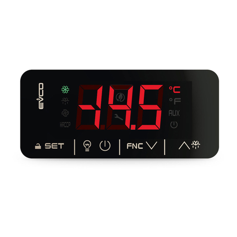
EV3B94 Controller for DHW tanks in heat pump version 1.0
EN ENGLISH
1 PREPARATIONS
1.1 Important
Carefully read these instructions before installing and using the prod-
uct. Pay close attention to the notes on installation and electrical wir-
ing connections; save these instructions together with the instrument
for future reference.
The device must be disposed of in compliance with
local Standards regarding the collection of electric
and electronic equipment.
1.2 Installation
Per panel using the snap-on brackets supplied; dimensions in mm (in).
DIMENS. MINIMUM TYPICAL MAXIMUM
A 71,0 (2,795) 71,0 (2,795) 71,8 (2,826)
B 29,0 (1,141) 29,0 (1,141) 29,8 (1,173)
Installation warnings:
• the thickness of the panel must not exceed 8.0 mm (0.314 in)
• make sure that the work conditions (temperature of use, humidity,
etc.) lie within the limits indicated in technical data
• do not install the device near to any heat sources (heating elements,
hot air ducts etc.), equipment containing powerful magnets (large
diffusors, etc), areas affected by direct sunlight, rain, humidity, exces-
sive dust, mechanical vibrations or shocks.
• in compliance with Safety Standards, the device must be installed
correctly and in a way to protect against any contact with electric
parts; all parts that ensure protection must be fixed in a way that they
cannot be removed without the use of tools.
1.3 Electric connection
Warnings for the electric connection:
• do not use electric or pneumatic screwdrivers on the terminal boards
• if the device has been taken from a cold to hot place, the humid-
ity could condense inside; wait about 1 hour before powering
it
• make sure that the power supply voltage, the frequency and the
operational electric power of the device, correspond with those of
the local power supply
• disconnect the power supply before proceeding with any type of
maintenance
• do not use the device as a safety device
• for repairs and information regarding the device, contact the EVCO
sales network.
2 USER INTERFACE
2.1 Preliminary notes
Operating Statuses:
• “on” status (the instrument is powered and on: the regulators can be
switched on)
• the “stand-by” status (the device is powered but is off via software: the
relays are off)
Hereon, the term “switch on” means the passage from the stand-by
status to the on status. The term “switch off” means passage from the on
status to the stand-by status.
When powered, the device will be in the same status as when the
power supply was cut-off.
2.2 Instrument manual switch-on/off
• Make sure that the keyboard is not locked and that no other proce-
dure is in progress
• press for 4 s.
2.3 The display
If the device is on, during normal operation the display will show the
magnitude established with parameter P5:
• if P5 = 0, the display will show the temperature of the upper part of
the DHW tank
• if P5 = 1, the display will show the current work set point
• if P5 = 2, the display will show the temperature of the lower part of
the DHW tank
• if P5 = 3, the display will show the evaporator temperature.
During the stand-by status the display is off.
2.4 Display of the type of operation in progress
• Make sure that the keyboard is not locked and that no other proce-
dure is in progress
• press for 2 s. the display will show one of the codes in-
cluded in the following table.
CODE MEANING
ECO “economy” operation
ObS “overboost” operation
Auto “comfort” operation
Anti “antilegionella” operation
dEFr defrosting
in2 active additional photovoltaic input
The display will show each code for 3 sec.
If the “Anti” code flashes:
• the temperature detected by the probe in the lower part of the
DHW tank is below the work set point during “economy” opera-
tion.
• the temperature detected by the probe in the lower part of the
DHW tank will be below the work set point during “comfort”
operation.
2.5 Manual Activation of Defrosting
• Make sure that the keyboard is not locked and that no other proce-
dure is in progress
• press for 4 s.
If the evaporator probe function is that of the defrosting probe (param-
eter P3=1) and upon activation of defrosting, the temperature of the
evaporator is higher than that established with parameter d2, the
defrosting function will not be activated.
2.6 Keyboard locking/unlocking
To lock the keyboard proceed as follows:
1. Make sure no procedure is in progress.
2. Do not operate for 30 s: the display will show the message “Loc”
for 1 s and the keybord shall lock automatically.
To unlock the keyboard:
3. Touch a key for 1 s: the display will show the message “UnL” for
1 s.
2.7 Silencing the buzzer
• make sure that no other procedure is in progress.
• press a key (pressing the key does not cause the associated effect).
If parameter u9 is set at 0, the buzzer will not be activated.
3 OPERATION
3.1 “economy” operation
During “economy” operation (i.e. if “comfort”, “overboost”,
“antilegionella” or defrosting operations are not in progress), the
compressor is switched on when the temperature of the lower part of
the DHW tank drops below the “ work set point SP1 - r0” and is switched
off when the temperature is above the work set point SP1.
During this operation, the fan works in parallel to the compressor and
the heating elements remain off.
3.2 “antilegionella” operation
The heating elements remain on in a cyclical mode (the parameter
H0 establishes the switch-on interval and the parameter H1 the tem-
perature to be reached; the differential of the parameter H1 is 2 °C/
4 °F).
If a power cut occurs during the countdown of the time established
with parameter H0, when the power is restored, the countdown will
be re-started with a max error of 30 minutes.
The function is activated on condition that:
• the temperature detected by the probe in the lower part of the
DHW tank is above the work set point during “economy” opera-
tion.
• the temperature detected by the probe in the lower part of the
DHW tank is above the work set point during “comfort” opera-
tion.
When the temperature of the lower part of the DHW tank reaches that
established with parameter H1, the heating elements remain on for
the time established with parameter H3, after which the function is
deactivated.
If there is a power cut during the countdown established with param-
eter H3, when the power is restored the countdown will be re-started
from the beginning, but on condition that the temperature of the
lower part of the DHW tank has again reached that established with
parameter H1 (or when it reaches it again).
If the function is in progress and the instrument is switched off due to
the HOF1 and HOF2 parameters, the function is completed.
3.3 “Comfort” operation
During “comfort” operation,the compressor is switched on when the
temperature of the lower part of the DHW tank drops below the work
set point SP2 - r0” and is switched off when the temperature is above
the work set point SP2.
During this operation, the heating elements are also switched on when
the temperature of the upper part of the DHW tank and that of the
lower part drop below the “work set point SP2-r0” and are switched
off when the temperature of the upper part of the DHW tank is above
the work set point SP2.
During this operation, the fan operates in parallel to the compressor.
The “comfort” function can also be activated in manual mode, with
the following procedure:
• Make sure that the keyboard is not locked and that no other proce-
dure is in progress
• hold the key down for 1 s: the display will show the first
label available
• press and release the key or the key to select
“Auto”
• press and release the key
To exit the procedure before the operation is complete:
• press and release : operation will not be activated.
The “comfort” operation can be deactivated with the following pro-
cedure:
• Make sure that the keyboard is not locked and that no other proce-
dure is in progress
• hold the key down for 1 s: the display will show the first
label available
• press and release the key or the key to select
“ECO”.
• press and release the key
To exit the procedure before the operation is complete:
• press and release : operation will not be deactivated.
3.4 Defrosting
Defrosting can be activated in one of the following ways:
• automatically (when the temperature of the evaporator has remained
below the temperature esta blished with parameter d17 for the time
established with parameter d18)
• in manual mode (by pressing the key for 4 sec).
Defrosting is activated on the condition that the compressor
has remained on for at least the time established with param-
eter d18.
If the parameter P4 is set at 0 or 2, the parameter d3 will establish the
duration of defrosting; if the parameter P4 is set at 1, the parameter d3
will establish the defrosting end temperature and parameter d3 the
maximum duration of defrosting.
Defrosting the defrost:
• if parameter d1 is set at 1, the compressor will be on (off otherwise)
• if parameter d1 is set at 0 or 1, the defrosting output will be active (off
otherwise)
• d1 is set at 2, the fan will be on (off otherwise).
If an “antilegionella” or “overboost” function is in progress, defrosting
will not be activated.
3.5 The “overboost” function
During the “overboost” function, the compressor, the fan and the
heating elements are on, until the temperature of the upper part of the
DHW tank rises above the work set point SP1.
To activate the “overboost” function:
• make sure that the keyboard is not locked and that no other opera-
tion is in progress; ensure that the “economy” operation is not in
progress
• hold the key down for 1 s: the display will show the first
label available
• press and release the key or the key to select
“ObS”.
• press and release the key
To exit the procedure before the operation is complete:
• press and release : the function will not be activated.
The function is activated on condition that the temperature detected
by the probe in the lower part of the DHW tank and that of the upper
part are below set point SP3.
When the function is in progress, the display shows “ObS” 1 sec every
4 sec.
3.6 The “additional photovoltaic” function
During the “additional photovoltaic” function, the instrument works
as if during comfort operation, with the difference that the work set
point SP2 is SP6.
To activate the “additional photovoltaic” function, the photovoltaic
input must be activated.
3.7 Function “green” (only if parameter i0 has value 2)
If the water temperature is above the temperature you have set with
parameter SP8 and the multipurpose input is active (green modality),
the compressor will be switched off.
EVCO S.p.A. • Code 1043B94E104 • page 2/4
Once the time you have set with parameter C13 has elapsed since the
input has been deactivated, the comp. could be switched on again.
Function antilegionella has the priority on function “green”.
3.8 Cold evaporator control
Once the time you have set with parameter C12 has elapsed, if the
evaporator temperature is below that you have set with parameter
SP9, the compressor will not be switched on and the water will be
heated thanks to the contribution of the heater; the control will be
done periodically (parameter C11).
3.9 Evaporator damaged control
Once the time you have set with parameter C14 has elapsed, if the
evaporator temperature is below that you have set with parameter
S10, the compressor and the evaporator fan will be switched off and
the water will be heated thanks to the contribution of the heater.
4 SETTINGS
4.1 Setting the work set point during “economy” opera-
tion
• Make sure that the keyboard is not locked and that no other proce-
dure is in progress
• press the display will show “SP1”
• press the LED will flash
• press or within 15 sec; see also parameters r1, r2
and r3
• press or do not operate for 15 s. the LED will switch off.
• press and release the key.
To exit the procedure before the operation is complete:
• do not operate for 15 sec (any changes will be saved).
It is also possible to set the work during “economy” operation using
the parameter SP1.
4.2 Setting the work set point during “comfort” operation
• Make sure that the keyboard is not locked and that no other proce-
dure is in progress
• press the display will show “SP1”
• press or to select “SP2”
• press the LED will flash
• press or within 15 sec; see also parameters r1, r2
and r3
• press or do not operate for 15 s. the LED will switch off.
• press and release the key.
To exit the procedure before the operation is complete:
• do not operate for 15 sec (any changes will be saved).
It is also possible to set the work set point during “comfort” operation
using the parameter SP2.
4.3 Setting the temperature below which it is possible to
start the “overboost” function
• Make sure that the keyboard is not locked and that no other proce-
dure is in progress
• press the display will show “SP1”
• press or to select “SP3”
• press the LED will flash
• press or within 15 sec; see also parameters r1, r2
and r3
• press or do not operate for 15 s. the LED will switch off.
• press and release the key.
To exit the procedure before the operation is complete:
• do not operate for 15 sec (any changes will be saved).
It is also possible to set the temperature below which it is possible to
start the “overboost” function using parameter SP3.
4.2 Setting the configuration parameters
To access the procedure:
1. Make sure no procedure is in progress.
2. Touch the ey for 4 s: the display will show “PA”.
3. Touch the key.
4. Touch the or key within 15 s to set the value
determined with the “PAS” parameter (the parameter is set at “-
19” by default).
5. Touch the or do not operate for 15 s: the display will
show “SP”.
To select a parameter:
6. Touch the or key.
To set a parameter:
7. Touch the key.
8. Touch the or key within 15 s.
9. Touch the key or do not operate for 15 s.
To exit the procedure:
10. Touch the key for 4 s or do not operate for 60 s (any
changes will be saved).
After setting the parameters, suspend power supply flow to the device.
4.3 Manufacturer’s settings
To access the procedure:
1. Make sure no procedure is in progress.
2. Touch the key for 4 s: the display will show “PA”.
3. Touch the key.
To restore the manufacturer’s settings:
4. Touch the or key within 15 s to set “149”.
5. Touch the key or do not operate for 15 s: the display
will show “dEF”.
6. Touch the key.
7. Touch the or key within 15 s to set “4”.
8. Touch the key or do not operate for 15 s: the display
will show a flashing “- - -” for 4 s, after which the device will exit
the procedure.
9. Cut the device power supply off.
Make sure that the manufacturer’s settings are appropriate; see ch. 9.
To store customized settings as manufacturer’s:
10. Set the configuration parameters (with the procedure described
in paragraph 4.2).
11. From step 4. touch the or ekey within 15 s to
set “161”.
12. Touch the key or do not operate for 15 s: the display
will show “MAP”.
13. Repeat steps 6. 7. 8. and 9.
To exit the procedure in advance:
14. Touch the key for 4 s during the procedure (i.e. before
setting “4”: Restore will not be performed).
5 COMPRESSOR OPERATING HOURS COUNT
5.1 Preliminary notes
The instrument is able to store up to 9,999 hours of compressor op-
eration, after which the number “9999” starts flashing.
5.2 Display of Compressor Operation Hours
• Make sure that the keyboard is not locked and that no other proce-
dure is in progress
• hold the key down for 1 s: the display will show the first
label available
• press and release the key or the key to select “CH”.
• press and release the key.
To exit the procedure:
• press and release the key or do not operate for 60 sec
• press and release the or key until the display
shows the temperature established with parameter P5 or do not
operate for 60 sec.
Alternatively:
• press and release the key.
5.3 Cancelling Compressor Operation Hours
• Make sure that the keyboard is not locked and that no other proce-
dure is in progress
• hold the key down for 1 s: the display will show the first
label available
• press and rel. the key or the key to select “rCH”.
• press and release the key
• press and release the key or the key within15 sec
to set “149”.
• press and release the key or do not operate for 15 sec the
display will show a flashing “- - - -” for 4 sec then the instrument will
exit the procedure.
6 SIGNALS
6.1 Signals
LED MEANING
compressor LED light
if the LED is on, then the compressor is on
if the LED is flashing:
• the working set point is in the process of being changed
(via the procedure described in par. 4.2, 4.3 and 4.4)
• compressor protection operation in progress:
- parameters C0, C1, C2
- parameters i2 and i7
Defrost LED
If it is on:
• defrosting is in progress
AUX Heating elements LED
if on, the heating elements will be on
Fan LED
if the LED is on, then the fan is on
maintenance LED
if on, compressor maintenance is required:
- parameter C10
HACCP Alarms LED
if it is on, an alarm or error is in progress
°CCelsius grade LED
if it is on, the unit of measurement of the temperature will
be the degree Celsius:
- parameter P2
°FFahrenheit grade LED
if it is on, the unit of measurement of the temperature will
be the degree Fahrenheit:
- parameter P2
on/stand-by LED
if it is on, the device will be in the stand-by status
CODE MEANING
Loc the keyboard is blocked; see paragraph 2.6
ObS the “overboost” function is in progress
7 ALARMS
7.1 Alarms
CODE MEANING
AL Minimum alarm temperatures
Solutions:
• check the temperature associated to the alarm
• see parameters A0, A1, A2 and A11
Main consequences:
• the instrument will continue to function normally
AH Maximum temperature alarm
Solutions:
• check the temperature associated to the alarm
• see parameters A3, A4, A5 and A11
Main consequences:
• the instrument will continue to function normally
id Multipurpose input alarm
Solutions:
• check the causes of input activation
• see parameters i0 and i2
Main consequences:
• the compressor will be switched off
iSd Blocked instrument alarm
Solutions:
• check the causes of multipurpose input activation
• switch off and re-start the instrument or suspend the
power supply
• see parameters i0, i2, i8 and i9
Main consequences:
• the compressor will be switched off
• the heating elements will operate like the compressor
during economy operation (see paragraph 5.1)
FiL Maintenance alarm
Solutions:
• see parameter C10
• press and release a key to silence the buzzer; silencing the
buzzer also causes the deletion of the compressor oper-
ating hours
Main consequences:
• the instrument will continue to function normally
UtL Evaporator probably dirty alarm
Solutions:
• see parameters S10 and C14
• check the evaporator
Main consequences:
• the compressor and the fan will be switched off; the water
heating goes on because of the heater
When the problem that caused the alarm disappears, the instrument
returns to normal operation, except during blocked instrument alarm
(code “iSd”) and the evaporator probably dirty alarm (code “UtL”)
which require that the instrument is switched off or the power supply
cut off.
8 INTERNAL DIAGNOSTICS
8.1 Internal diagnostics
CODE MEANING
Pr1 DHW tank upper part probe error
Solutions:
• see parameter P01
• check the integrity of the probe
• check the device-probe connection
• check the temperature of the upper part of the DHW tank
Main consequences:
• the regulators will switch off
Pr2 DHW tank lower part probe error
Solutions:
• the same as the previous case but relative to the DHE tank
lower part probe
Main consequences:
• the regulators will switch off
Pr3 Evaporator probe error.
Solutions:
• the same as the preceding case but with respect to the
evaporator probe
Main consequences:
• the instrument will continue to function normally
When the problem that caused the alarm disappears, the instrument
returns to normal operation.
9 TECHNICAL DATA
9.1 Technical data
Purpose of the command device: operating command device.
Construction of the command device: built-in electronic de-
vice.
Container: grey self-extinguishing.
Heat and fire protection class: D.
Dimensions: according to model:
- 75,0 x 33,0 x 59,0 mm (2,952 x 1,299 x 2,322 in;
L x H x P) with fixed screw connection terminal blocks
- 75,0 x 33,0 x 81,5 mm (2,952 x 1,299 x 3,208 in;
L x H x P) with removable screw connection terminal blocks.
Method of mounting the command device: on panel, with
snap-in brackets.
Shell protection rating: IP65 (the front one).
Connection method: according to model:
- fixed screw connection terminal blocks for wires up to 2.5 mm²
(0.0038 in²): power supply, analog inputs, digital inputs and
digital outputs
- removable screw connection terminal blocks for wires up to 2.5
mm² (0.0038 in²): power supply, analog inputs, digital inputs
and digital outputs.
The maximum lengths of the connection cables are:
- power supply: 10 m (32.8 ft)
- analog inputs: 10 m (32.8 ft)
- digital inputs: 10 m (32.8 ft)
- digital outputs: 10 m (32.8 ft).
Operating temperature: from 0 to 55 °C (from 32 to 131 °F).
Storage temperature: from -25 to 70 °C (from -13 to 158 °F).
Humidity for use: from 10 to 90 % relative humidity without con-
densate.
EVCO S.p.A. • Code 1043B94E104 • page 3/4
Command device pollution situation: 2.
Environmental standards:
- RoHS 2011/65/CE
- WEEE 2012/19/EU
- REACH (CE) regulation n. 1907/2006.
EMC standards:
- EN 60730-1
- IEC 60730-1.
Power supply: 115... 230 VAC (+10 % -15 %), 50... 60 Hz (±3 Hz),
3.2 VA max.
Control device grounding method: none.
Rated impulse voltage: 2.5 KV.
Overvoltage category: II.
Class and structure of software: A.
PT • 04/17
Analog inputs: 3 inputs (lower part of the DHW tank, upper part of
the DHW tank and evaporator) configurable via configuration param-
eter for PTC or NTC probes.
Analog inputs PTC (990 W @ 25 °C, 77 °F)
Type of sensor: KTY 81-121.
Measurement field: from -50 to 150 °C (from -58 to 302
°F).
Resolution: 0,1 °C (1 °F).
Analog inputs NTC (10 KW @ 25 °C, 77 °F)
Type of sensor: ß3435.
Measurement field: from -40 to 105 °C (from -40 to 221
°F).
Resolution: 0,1 °C (1 °F).
Digital inputs: 2 inputs (multipurpose and additional photovoltaic
supplement).
Digital inputs (free of voltage contact 5 VDC 2 mA)
Displays: 3 digit custom display, with function icons.
Digital outputs:
- 1 output (16 A res. @ 250 VAC) for compressor management
- 1 output (8 A res. @ 250 VAC) for defrost management
- 1 output (8 A res. @ 250 VAC) for fan management
- 1 output (SPST electromechanical relay with 8 A res. @ 250 VAC)
for heater management.
The maximum allowable current on the loads in 10 A.
The device guarantees double insulation between each connector of
the digital outputs and the other parts of the device.
Type 1 or Type 2 actions: type 1.
Complementary features of Type 1 or Type 2 actions: C.
10 WORKING SETPOINT AND CONFIGURATION PARAMETERS
10.1 Working set-point
MIN. MAX. U.M. DEF.
r3 r4 °C/°F (1) 55,0
r1 r2 °C/°F (1) 65,0
r1 r2 °C/°F (1) 45,0
10.2 Configuration parameters
PARAM. MIN. MAX. U.M. DEF.
SP1 r3 r4 °C/°F (1) 55,0
SP2 r1 r2 °C/°F (1) 65,0
SP3 10.0 r2 °C/°F (1) 45,0
SP5 r1 SP2 °C/°F (1) 55,0
SP6 40.0 100.0 °C/°F (1) 75,0
SP7 0.0 40.0 °C/°F (1) 5,0
SP8 0.0 100.0 °C/°F (1) 40,0
SP9 -25.0 25.0 °C/°F (1) -7,0
S10 -50.0 25.0 °C/°F (1) -25,0
PARAM. MIN. MAX. U.M. DEF.
CA1 -25,0 25,0 °C/°F (1) 3,0
CA2 -25,0 25,0 °C/°F (1) 3,0
CA3 -25,0 25,0 °C/°F (1) 0,0
P0 0 2 - - - - 1
P1 0 1 - - - - 1
P2 0 1 - - - - 0
P3 0 1 - - - - 0
P4 0 2 - - - - 1
P5 0 3 - - - - 0
P6 0 3 - - - - 0
P8 0 250 0.1 s 5
PARAM. MIN. MAX. U.M. DEF.
r0 0,1 30,0 °C/°F (1) 2,0
r1 10,0 r2 °C/°F (1) 40,0
r2 r1 199,0 °C/°F (1) 70,0
r3 10,0 r4 °C/°F (1) 40,0
r4 r3 199,0 °C/°F (1) 55,0
r5 0 1 - - - - 0
PARAM. MIN. MAX. U.M. DEF.
C0 0 240 min 5
C1 0 240 min 5
C2 0 240 min 5
C3 0 240 s 0
C10 0 9999 h 400
C11 0 999 min 120
C12 0 240 min 1
C13 0 240 min 20
C14 -1 240 min 20
PARAM. MIN. MAX. U.M. DEF.
d1 0 2 - - - - 2
d2 -50,0 50,0 °C/°F (1) 3,0
d3 0 99 min 30
d17 -50,0 50,0 °C/°F (1) 2,0
d18 0 240 min 30
WORKING SETPOINT
work set point during “economy” operation
work set point during “comfort” operation
temperature below which it is possible to start the “overboost” function
WORKING SETPOINT
work set point during “economy” operation
work set point during “comfort” operation
work set-point
work set-point to stop the heat pump
work set-point to activate the photovoltaic input
work set-point for antifreeze cycle
work set point during “green” operation
evaporator temperature below which the cold evaporator alarm is activated
evaporator temperature below which the evaporator damaged alarm is activated
MEASUREMENT INPUTS
DHW tank upper part probe offset
DHW tank lower part probe offset
offset evaporator probe
probe type
0 = PTC
1 = NTC
1 = Pt 1000
Celsius degree decimal point (for size displayed during normal operation)
1 = YES
temperature unit of measurement (2)
0=°C
1=°F
number of probes enabled to work
0 = 1 probe (DHW tank lower part probe; all regulations joined to the upper part probe make reference to the lower part probe)
1 = 2 probes (DHW tank upper part probe offset and DHW tank lower part probe offset)
evaporator probe function
0 = probe absent
1 = probe for activation and end of defrosting
2 = probe for activation of defrosting
magnitude displayed during normal operation
0 = DHW tank upper part probe offset
1 = work set-point
2 = DHW tank lower part probe
3 = evaporator temperature
magnitude displayed during normal operation
0 = DHW tank upper part probe offset
1 = work set-point
2 = DHW tank lower part probe
3 = evaporator temperature
delay displaying temperature variation detected by the probes
MAIN REGULATOR
working set-point differential
minimum working set-point for “comfort” operation
maximum working set-point for “comfort” operation
minimum working set-point for “economy” operation
maximum working set-point for “economy” operation
locking of working set-point calibration (using the procedure described in paragraph 4.2, 4.3 or 4.4)
1 = YES
COMPRESSROR PROTECTION SYSTEM
compressor delay from instrument switch-on (3)
minimum time between two consecutive compressor switch-ons (4)
minimum duration of compressor switch off time (4)
minimum duration of compressor switch on time
number of operating hours is higher than the limit at which the need for maintenance is signalled.
0 = function absent
sampling interval to read the evaporator temperature to evaluate cold evaporator
minimum delay between the fan switches on and the compressor switches on to read the evaporator temperature to evaluate cold evaporator
time between the multipurpose input is deactivated and the compressor switches on (only if i0 = 2)
consecutive time the compressor is switched on such as to provoke the compressor and fan shut down to signal the evaporator is damaged
1 = YES
DEFROSTING
type of defrosting
0 = electric
1 = with hot gas
1 = to stop the compressor
defrosting end temperature (only if P4 = 1)
defrosting duration if P3 = 0 or 2; maximum defrosting duration if P3 = 1
0 = defrosting will not be activated
evaporator temperature above which the time count d18 is suspended
defrosting interval due to effect of the evaporator temperature (defrosting will be activated when the evaporator temperature has remained below d17 for time d18)
EVCO S.p.A. This document belongs to EVCO; unless you are authorized by EVCO, you can not publish this document.
Via Feltre 81, 32036 Sedico Belluno ITALIA EVCO does not assume any liability regarding Features, technical data and the possible errors stated in this document.
Telephone 0437-8422 • Fax 0437-83648 EVCO does not take any responsibility about damages coming by the non-observance of additional information.
[email protected] • www.evco.it EVCO reserves the right to make any change without prior notice and at any time without prejudice the basic safety and operating features.
EVCO S.p.A. • Code 1043B94E104 • page 4/4
PARAM. MIN. MAX. U.M. DEF.
A0 0 2 - - - - 0
A1 0,0 50,0 °C/°F (1) 10,0
A2 0 1 - - - - 0
A3 0 2 - - - - 0
A4 0,0 199,0 °C/°F (1) 90,0
A5 0 1 - - - - 1
A6 0 240 min 120
A7 0 240 min 15
A11 0,1 30,0 °C/°F (1) 2,0
PAR. MIN. MAX. U. M. DEF.
H0 0 9 9 d (days) 3 0
H1 10.0 199.0 °C/°F (1) 70.0
H3 0 240 min 2
PAR. MIN. MAX. U. M. DEF.
i0 0 2 - - - - 2
i2 0 120 min 0
i3 0 1 - - - - 1
i4 0 1 - - - - 0
i8 0 1 5 - - - - 0
i9 1 999 min 240
PAR. MIN. MAX. U. M. DEF.
u9 0 1 - - - - 1
(1) the unit of measurement depends on P2
(2) Properly set the parameters corresponding to the regulators after modifying parameter P2
(3) the parameter also has effect after a power cut, which occurs when the device is on
(4) the time established with the parameter is counted also during the stand-by status
(5) make sure that the time established with parameter i7 is less than that established with parameter i9
(6) if when defrosting is activated, the operating duration of the compressor is less than the time established with parameter dA, the compressor will remain on for the amount of time necessary to
complete defrosting.
TEMPERATURE ALARMS
temperature associated with the minimum temperature alarm
0 = temperature of the upper part of the DHW tank
1 = temperature of the lower part of the DHW tank
2 = evaporator temperature
temperature below that at which the minimum temperature alarm is activated; see also A0, A2 and A11
minimum temperature alarm type
0 = alarm absent
1 = absolute (that is A1)
temperature associated with the maximum temperature alarm
0 = temperature of the upper part of the DHW tank
1 = temperature of the lower part of the DHW tank
2 = evaporator temperature
temperature higher than that at which the maximum temperature alarm is activated; see also A5 and A11
maximum temperature alarm type
0 = alarm absent
1 = absolute (that is A4)
delay in maximum temperature alarm after the instrument is switched on (3)
temperature alarm delay
differential of parameters A1and A4
HEATING ELEMENTS
heating elements switch-on interval (due to effect of the “antilegionella” function) (4)
0 = the “antilegionella” function at intervals will never be activated (it can only be activated in manual mode)
temperature of the upper part of the DHW tank reached at which the heating elements remain on further for the time established with parameter H3 (due to effect of the
“antilegionella” function)
duration of heating elements switch-on (due to effect of the “antilegionella” function) from the moment that the temperature of the upper part of the DHW tank has reached
that established with parameter H1
DIGITAL INPUTS
kind of multipurpose input
0 = evaporator probe error
1 = high pressure
2 = green
compressor switch-on delay from the deactivation of the multipurpose input; the compressor protections are respected (5)
enabling of the “additional photovoltaic” function
1 = YES
type of photovoltaic input contact
0 = normally open (active input with closed contact)
1 = normally closed (active input with open contact)
number of multipurpose input alarms (code “id”) such to cause the blocked instrument alarm (code “iSd”)
0 = alarm absent
time that must pass in absence of multipurpose input alarms (code “iA”) so that the alarm counter is reset
DIGITAL OUTPUTS
enabling of buzzer
1 = YES

Other Evco Controllers manuals

Evco EVX225 User manual

Evco

Evco EVX225 User manual

Evco EVF214 User manual

Evco

Evco EVF214 User manual

Evco EV3143 User manual

Evco

Evco EV3143 User manual

Evco EVJ 700 Instructions for use

Evco

Evco EVJ 700 Instructions for use

Evco EC 6-295 User manual

Evco

Evco EC 6-295 User manual

Evco c-pro 3 micro CHIL Series Instructions for use

Evco

Evco c-pro 3 micro CHIL Series Instructions for use

Evco EVD MVC Series User manual

Evco

Evco EVD MVC Series User manual

Evco EV3271 User manual

Evco

Evco EV3271 User manual

Evco Vcolor 318 M User guide

Evco

Evco Vcolor 318 M User guide

Evco EV3B24 User manual

Evco

Evco EV3B24 User manual

Evco EV3143 User manual

Evco

Evco EV3143 User manual

Evco Vcolor 338 L User guide

Evco

Evco Vcolor 338 L User guide

Evco EVXS815 User guide

Evco

Evco EVXS815 User guide

Evco EV3B94 User manual

Evco

Evco EV3B94 User manual

Evco c-pro 3 micro AHU User manual

Evco

Evco c-pro 3 micro AHU User manual

Evco Vcolor 229 Series User manual

Evco

Evco Vcolor 229 Series User manual

Evco Vcolor 388 User guide

Evco

Evco Vcolor 388 User guide

Evco EV9376 User manual

Evco

Evco EV9376 User manual

Evco EV3 HP User guide

Evco

Evco EV3 HP User guide

Evco Vcolor 338 User guide

Evco

Evco Vcolor 338 User guide

Evco EV3802 User manual

Evco

Evco EV3802 User manual

Evco EV3C23 User manual

Evco

Evco EV3C23 User manual

Evco EV3 700 Series User manual

Evco

Evco EV3 700 Series User manual

Evco EVJ825P9VX3 User guide

Evco

Evco EVJ825P9VX3 User guide

Popular Controllers manuals by other brands

Moen ARC-4200 installation guide

Moen

Moen ARC-4200 installation guide

SEW MOVIFIT-SC manual

SEW

SEW MOVIFIT-SC manual

Siemens SFP21/18 manual

Siemens

Siemens SFP21/18 manual

Maretron MPOWER CLMD16 Configuration guide

Maretron

Maretron MPOWER CLMD16 Configuration guide

Weishaupt W-FM 100 Installation and operating instruction

Weishaupt

Weishaupt W-FM 100 Installation and operating instruction

Emerson Dixell XR70T Installing and operating instructions

Emerson

Emerson Dixell XR70T Installing and operating instructions

Cisco 4404 - Wireless LAN Controller quick start guide

Cisco

Cisco 4404 - Wireless LAN Controller quick start guide

LOVATO ELECTRIC RGAM 20 instruction manual

LOVATO ELECTRIC

LOVATO ELECTRIC RGAM 20 instruction manual

dixell XR40D Installing and operating instructions

dixell

dixell XR40D Installing and operating instructions

Danfoss ECL Comfort 210 installation guide

Danfoss

Danfoss ECL Comfort 210 installation guide

CardAccess inhome IGA10A installation guide

CardAccess

CardAccess inhome IGA10A installation guide

Delta Regis POSITX-3D user manual

Delta Regis

Delta Regis POSITX-3D user manual

SICK Flexi Classic operating instructions

SICK

SICK Flexi Classic operating instructions

GEM 658 Installation, operating and maintenance instructions

GEM

GEM 658 Installation, operating and maintenance instructions

Lightolier DRCP operating instructions

Lightolier

Lightolier DRCP operating instructions

Johnson Controls VA9208-AG Series installation instructions

Johnson Controls

Johnson Controls VA9208-AG Series installation instructions

Schmidlin TOUCH CONTROL Instructions for use

Schmidlin

Schmidlin TOUCH CONTROL Instructions for use

LEYBOLD GRAPHIX ONE instruction manual

LEYBOLD

LEYBOLD GRAPHIX ONE instruction manual

manuals.online logo
manuals.online logoBrands
  • About & Mission
  • Contact us
  • Privacy Policy
  • Terms and Conditions

Copyright 2025 Manuals.Online. All Rights Reserved.