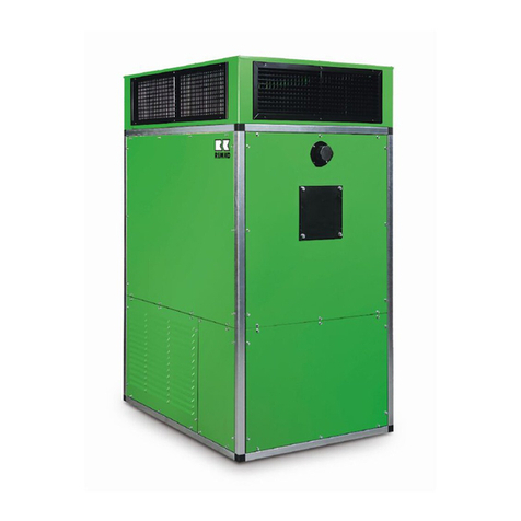
REMKO VRS 40 User manual

VRS 40 -450
Oil-/Gas-Universal
Heating Systems
Edition GB -H01 (S)
Operating
Technology
Original
REMKO
Spare Parts
REMKO -alles bärenstark.


3
Contents Page
Safety Instructions 4
Description 4
Safety Facility 5
Installation Requirements 6-8
Chimneys 8-9
Installation and Assembly 9-10
Start-up 11-12
Shut-down 12
Maintenance 12-13
Contents Page
Technical Data I 14
Technical Data II 15
Drawing 16
List of Spare Parts 17
Block Diagram 230 V 18
Circuit Diagram 400 V /up to 3.3 kW 19
Circuit Diagram 400 V /up from 4.0 kW 20-21
Troubleshooting Instructions 22
Important!
Always keep these operating instructions
near or on the device.
Operating Instructions
The regulations, ordinances, standards, etc. mentioned in this document are
valid for Germany. In other countries, different regulations may be applicable.
Make sure to read these instructions carefully before starting/using the unit!
Our guarantee will become void when the unit supplied by us is used and installed
for inadequate purposes, or maintained incorrectly, etc.,
or if it is changed without our prior consent.
VRS 40 –VRS 450
standing device lying device
GG

4
Safety Instructions
Always observe the local building and fire
prevention regulations.
l The heaters may only be operated by persons who
have been instructed how to operate them.
lThe heaters must be installed and operated so that
their radiated heat does not endanger persons wor-
king in their vicinity and that no fires can break out.
lThe heaters may only be installed and operated in
rooms if they are supplied with sufficient air for
combustion.
If this cannot be ensured, a separate burner fresh-
air draw-in facility supplying air from the open must
be installed.
lThe heaters may only be installed on a non-
inflammable surface.
lThe heaters may only be mounted to structures or
ceilings with a sufficient weight-bearing capacity.
They must be mounted with stable anchors, which
are to be fastened to the heater.
lDo not install or operate the heaters in rooms or
areas exposed to fire or explosion hazards.
lInstall the heaters outside thoroughfares, in
particular also outside the reach of cranes.
Provide a 1 m protection zone around the heater.
lThe suction protection grids must always be free
from dirt and loose matter.
lNever stick any foreign objects into the heater.
lDo not expose the heaters to direct jets of water.
lNever let water get into the interior of the heater.
lThe heaters are not designed for domestic heating
etc.
lProtect all electricity cables outside the heaters
from damage (e.g. by rodents).
Before carrying out any maintenance or repairs on
the device, always disconnect it from the mains
(remove the fuse or switch off the main switch of
the electrical installation).
It is not sufficient to switch off
the on/off switch of the device!
G
Description of Device
²The heaters are directly fired with heating oil or natu-
ral gas resp. liquefied petroleum gas.
²The heaters are designed for fully-automated, univer-
sal, problem-free operation.
²The devices are operated with separate forced-air
burners and must be connected to chimneys.
²They are equipped with a powerful low-noise and
low-maintenance radial fan with a drive motor as well
as attached switchboxes and control equipment.
²The heaters are safe and easy to operate.
The devices are exclusively intended for industrial
and commercial use, for
−heating or tempering of workshops
−heating or tempering of warehouses
−heating or tempering of exhibition halls
−heating or tempering of fair pavilions
−heating or tempering of lightweight halls
−heating or tempering of sales rooms
−heating or tempering of greenhouses
Working of Device
After the device had been switched on or when the
room temperature has fallen below the selected level
(fully automated heating with room thermostat), the
forced-air oil or gas burner switches on automatically
(green indicator lamp on the switch box lights up).
The combustion chamber with heat exchanger now
heats up until the set temperature is reached.
After the set temperature has been reached, the air
supply fan automatically switches on (green indicator on
the switch box lights up). Warm air is blown out.
The triple combination control and the automatic burner
control unit handle all modes of operation automatically
and monitor them reliably. After the device has been
switched off with the operating switch or the room ther-
mostat, the air supply fan keeps running for a while until
it finally switches off automatically.
This function cycle repeats itself depending on the heat
requirement.
In the case of irregularities or when the flame extin-
guishes, the device is switched off by the automatic
burner control unit. The fault indication lamp of the
burner control unit and the red fault indicator lamp on
the switch box light up. The device cannot be restarted
until the burner control unit has been manually released.
A safety temperature limiter (STB) interrupts the burner
operation in the event of overheating.
The safety temperature limiter cannot be manually re-
leased until the device has cooled down.
Important!
Never disconnect the device from the mains supply
before the complete cool-down phase has ended
(except in emergency situations).

5
Safety Facility
Quadruple combination control
according to DIN 3440
This device has 4 functions:
Fan Control (TR)
Regulates the starting of the supply air fan.
The fan is switched on when reaching the pre-set tem-
perature and switched off after fallen below a tempera-
ture-difference of approx. 8K
The tripping point is set with the adjusting lever (fan).
Rated value approx. 60°C.
Burner Temperature Monitor (TW1)
No function in standard equipment.
Burner Temperature Monitor (TW2)
Regulates the starting of the burner.
The tripping point is set with the adjusting lever
(burner). Rated value approx. 80 °C.
In single-staged operation the burner is switched off
when reaching the pre-set temperature (80 °C) and
switched on after fallen below a temperature-difference
of appox. 8K
Safety Temperature Limiter (STB)
The tripping point is fixed according to DIN 3440.
After tripping, a burner restart is prevented.
The reset button is operated from outside.
Before reset, check operating conditions
of the device to ensure that the STB-
temperature is not exceeded again.
The safety facilities may neither be bridged nor
blocked while the heater is in operation!
G
Note!
This device is equipped with a sensor monitoring fea-
ture and is cold-resistant down to -20°C; below -20°C
the device switches off; when the temperature rises
above this temperature, it switches on again.
When the sensor or the capillary tube is damaged, or
when an overtemperature of approximately 220°C is
reached, the filling medium is emptied and the device
performs a safety switch-off operation.
The device is no longer operable and must be replaced.
lWhen the safety facility has to be replaced, take care
not to damage or excessively bend the capillary
tubes.
lDo not bend the sensor spirals.
lThe sensors must be located freely in the air current.
lThe sensors must always be free from dust and dirt.
lWhen replacing, use only the original spare part,
reference no. 1104270.
Do not jumper or obstruct the safety facilities while the heater is in operation! GG
STBTW1 TR
TW2
switching lever
burner TW1*) reset-button
STB switching lever
fan TR
switching lever
burner TW2
shown without housing cover
*) function only at 2-stage operation (special edition)

6
Installation Requirements
The heaters may only be installed in compliance with
the relevant regulations, especially regulations go-
verning the installation and operation of fireplaces and
furnaces.
Observe also any national/local emission control legis-
lation/regulations.
Use prototype-tested WLE-type oil burners or gas
burners only.
If the heater is supplied from the factory with an oil or
gas burner, it comes with separate instructions for the
burners.
Choice of the Place of Installation
When choosing the place of installation, observe the re-
quirements with regard to:
a) fire protection and operational hazards
b) function
(e.g. room heating, free-blowing or duct system,
above or below atmospheric pressure in the installa-
tion room)
c) operational requirements
(heat requirement, nominal air volume flow, need of
circulating air or supplied air, humidity, room tem-
perature, air distribution, space requirement)
d) connection to the chimney
e) installation, repair and maintenance
f) ratio of room volume to total nominal thermal output,
especially in rooms with natural ventilation.
Always install the heaters so that they are easy
to access for repair and maintenance.
Heaters with a nominal thermal output of up to 50 kW
may generally be installed outside heating rooms, pro-
vided that the national/local regulations governing the
installation and operation of fireplaces are complied
with. Heaters with a nominal thermal output of over 50
kW must be installed in heating rooms; this does not
apply to devices which are designed for installation
outside heating rooms or which are installed in in-
dustrial/commercial areas. Follow the building authori-
ties’ "guidelines for the installation of fireplaces with a
total nominal thermal output of more than 50 kW in
rooms other than heating rooms" (applicable in Ger-
many). These guidelines prohibit the installation of fire-
places in the case of hazardous concentrations of dan-
gerous substances according to the working media or-
dinance.
Before the installation of heatings is prohibited, the haz-
ardous concentration in the installation room and in the
adjacent rooms with openings to this room must be ex-
amined.
For rooms where readily flammable substances or mix-
tures are processed, stored or manufactured at such
quantities that their ignition causes hazards, exceptions
may be allowed when appropriate measures have been
taken to ensure that the fireplace cannot ignite the sub-
stances or mixtures.
Installation
−Install the heaters in a stable position on a non-
inflammable surface and outside thoroughfares as
well as e.g. outside the reach of cranes.
−Install and operate the heaters so as to avoid any
hazard to the personnel by fumes and radiation heat,
well as to avoid any risk of fire.
−Install the heaters so that they do not cause any
hazards and are no source of any unacceptable an-
noyance, e.g. through shocks, vibration or noise.
−Install the heaters that they are easy to access for
repair and maintenance.
−Any control elements whose improper operation may
cause dangerous operating conditions and which
are generally accessible must be protected against
unauthorised operation.
−If mixed-air valves (accessories) are installed, en-
sure that they are asynchronously coupled and pro-
vide a minimum cross section for an adequate out-
side-air rate.
−Heaters in rooms other than heating rooms must be
installed so that they can be constantly kept under
observation.
−Do not install or operate the heaters in rooms or ar-
eas exposed to fire or explosion hazards.
−The heaters may only be installed and operated in-
side rooms if they are supplied with sufficient air for
combustion and if the flue gases escape into the
open through flues.
The air supply is sufficient for combustion when, for ex-
ample, the cubic capacity of a room is at least ten times
the nominal thermal load of all heaters in the room, and
a natural exchange of air is ensured by means of win-
dows and doors.
The airing is sufficient when, for example,
1) the room capacity in m³ is at least 30 times the nomi-
nal thermal load in kW of all heaters in the room, and
a natural exchange of air is ensured by means of
windows and doors, or
2) there are air inlet and outlet openings, which cannot
be closed, near the ceiling and the ground; the size
of which in m² must be at least 0.003 times the nomi-
nal load in kW of all heating devices in the room.
G

7
Supply of Combustion Air
A sufficient supply of combustion air is ensured when
this combustion air is drawn from the
−installation room if this room meets the building
authorities’ requirements in terms of the ratio of room
capacity to total nominal thermal output (4m³/kW);
−installation room if this room is heated by the heater
in outside-air or mixed-air mode of operation with a
guaranteed rate of outside air; no room capacity-to-
output ratio needs to be observed;
−installation room if this room has openings to the
open air which cannot be closed, according to the
building authorities’ regulations for heating rooms;
−open air through a continuous supply conduit with an
adequate cross section connected to the burner or its
panelling; the cross section must be adapted to the
burner’s suction capacity and to any objects or condi-
tions resisting the suction (including the suction pro-
tection grid), so as to ensure adequate combustion.
Combustion Gas Outtake
The heaters must normally be connected to separate
chimneys. The chimney design must conform to DIN
18160 Part 1, the chimney dimensions to DIN 4705 Part
1 or Part 2 respectively. To ensure problem-free opera-
tion of the fireplace, the chimneys are to be located near
the roof ridge and exceed it in height by at least 0.5 m. If
dynamic pressures are to be expected, e.g. due to fall
winds or nearby buildings, the design of the chimney
head must take this into account.
Special authorisations for the construction of steel
chimneys will normally be granted, provided that
they do not cause any fire hazards.
The connecting pieces between the heater and the
chimney for flue gas outtake must comply with DIN
1298. The length of the connecting piece should not ex-
ceed 2 m.
Chimneys for flue gas outtake always need approval.
The chimneys may be of brickwork or metal.
Floor Mounting
Install the heaters in a stable position on a non-
inflammable surface and outside thoroughfares as well
as e.g. outside the reach of cranes.
Provide for a protection zone of 1 m around the heater
to protect it from damage in industrial or commercial
rooms, for unobstructed maintenance or repair of the
heater and the burner, and, according to the circum-
stances, for unhindered air intake and outtake.
Mark this protection zone with a label bearing the in-
scription:
"Protection zone -keep 1 m clear of the heater"
A barrier is recommended for thoroughfares.
Wall Mounting
The wall intended for mounting must consist of non-
inflammable building materials. Check its load-bearing
capacity, provide for reinforcements if necessary. Con-
soles must be sufficiently anchored to the wall, and the
heaters fastened on them.
Provide for sufficient maintenance possibilities for the
heat exchanger, burner, fan and chimney. The operating
facilities for the heater and the fuel supply must be ac-
cessible from the floor. The user must ensure that main-
tenance and repair can be carried out.
Installation of Suspended Heaters
The heaters may only be mounted to non-inflammable
structures or ceilings with a sufficient weight-bearing ca-
pacity. They must be mounted with stable anchors,
which are to be fastened to the heater.
In addition, the requirements specified under "Wall
Mounting" must be met.
Open-air Installation
Heaters operated in the open air must be so installed
and protected against atmospheric influence that they
do not cause any hazards or unacceptable annoyance.
In particular, they may only be equipped with mountings
and switchboxes suitable for open-air use, or the switch-
box and control equipment must be adequately pro-
tected.
Fuel Supply
Install the fuel supply in compliance with DIN 4755 for
oil-fired air heaters (WLE), DIN 4756 or the DVGW
worksheet G 600 for gas fired air heaters and the tech-
nical guidelines for liquid gas.
Ensure especially for heating oil conduits that their cross
sections are designed to take the suction height, any
conduit resistance and higher viscosity at low tempera-
tures into account, and that, if necessary, oil conveying
equipment is installed.
Lay the conduits so that they are easy to vent and that
there is no risk of corrosion or damage. The overpres-
sure measured in the suction conduit should not ex-
ceed -0.3 bar, its maximum permissible value is -0.5
bar. (According to DIN 1314, the term "negative pres-
sure" is no longer accepted).

8
Electrical Installation
Before carrying out the electrical installation in accor-
dance with DIN 57116/VDE, check whether any inad-
missible undervoltage due to mains overloads -even if
only temporal -can occur.
The cross sections of the heater connecting lines must
be so that no voltage dips occur at the burner even
when the fan starts to operate.
The heater switch box and the switch of any oil convey-
ing equipment must be installed close to each other and
must be easily accessible should dangerous situations
occur.
For heaters with a nominal thermal output of more than
50 kW, an emergency stop switch must be installed at
an easily accessible location outside the room where
the heater is installed. Protect it from unauthorised use.
Room Heating
In closed rooms/halls, air heaters may only be operated
with room thermostats.
Annual Check and Maintenance
According to the operating conditions, the heaters must
be checked as necessary, but at least once every year
by a qualified person whether they are still in a safe
condition.
The user must have the system checked at least once
every year by a person appointed by the supplier or an-
other qualified person to ensure its readiness for serv-
ice, its operating safety, and whether it works within the
emission limits. The combustion values are to be meas-
ured in accordance with the rules of the national emis-
sion regulations.
If any deficiencies are found, the user must be in-
structed to have the equipment repaired or components
replaced immediately.
Limiting equipment, automatic control elements and
flame monitoring equipment as well as other safety
equipment may only be repaired or overhauled by their
manufacturers or a person authorized by that company.
The qualified person carrying out the maintenance may
replace complete components or assemblies with oth-
ers of the same type.
These heaters are exclusively for industrial
and commercial use.
They are not intended for domestic heating etc.
G
Chimneys
Connect the devices to chimneys.
When the roof is also the ceiling of the installation
room, the chimney may be made of sheet steel.
Each fireplace must have its own chimney; it is not
allowed to combine sheet steel chimneys.
Through roofs, the chimney must be surrounded by a
tube sleeve to allow it to expand when it is hot.
Chimneys are structures in or on devices, which are
exclusively designed to carry off flue gases above the
roof.
The construction of a chimney always
requires an official approval.
In Germany, the following regulations and standards
are of a particular importance for the planning and
construction of chimneys:
−The applicable ordinance on fireplaces (FeuVo)
−The building regulations
−DIN 18160 Part 1
−DIN 4705 Part 1 and 2
−DIN 1056
−Technical regulations for gas installation
DVGW-TRGI
The chimney dimensions must be adapted to the device
output.
The chimneys may be of brickwork or metal
(single-or double-walled).
The effective chimney height must be at least 4 m.
The device connection must be without leakages and
must be secured against unintentional loosening (rivet/
screw).
Preferably a short horizontal flue gas duct is to be
provided (ascending slope of 2% = 2 cm/m)
The double-wall REMKO high-grade steel chimney
systems are approved by the German "Institut für
Bautechnik" according to DIN 18160 Part 1.
Sheet-steel chimneys for low duty require a special
approval. A prototype test is not required.
The chimney installation/assembly must be carried
out in a workmanlike manner in accordance with
the applicable regulations.
F

9
Installation
and Assembly
Device Installation
The device installation procedure must always conform
to the national/regional regulations and ordinances.
The heaters are suitable for the use of accessories on
the air outlet and inlet sides. Ensure that the fan output
(nominal pressure) is adapted to conditions interfering
with the air current (measure the nominal current). The
heaters are not suitable for being used exclusively as
supply-air heaters.
²Ensure that the heaters are installed in a stable
position.
²Always remove the transport pallet and slabs.
²In the case of floor mounting, install the heaters free
of tension and safely, preferably on a separate base.
²Air may be drawn in exclusively via the provided
intake openings. If the device baseplate is not
designed as an air suction variant, ensure that it is
always closed to avoid an unintentional drawing-in
of air.
²If considerable air contamination is to be expected in
the installation room, air must be drawn in through
appropriate filters (accessories). Take any conditions
causing resistance to suction into account and adapt
the fan performance accordingly.
²Ensure that the supply of combustion air is always
guaranteed. In the event of any overpressure or
negative pressure or highly contaminated air install a
burner fresh-air draw-in equipment.
²Ensure an unobstructed air intake and outtake.
Connection of the Flue Gas Outlet
Ensure proper conduction of the flue gas.
The design must comply with DIN 18160 Part 1, the
dimensions with DIN 4705 Part 1 or 2.
The connection of the flue gas outlet to the chim-
ney must be carried out in a workmanlike manner,
in accordance with the applicable regulations.
Important!
Flue gas outlets may only be connected to chimneys
that have previously been approved.
Electrical Installation
The electrical connection of the heater is to be carried
out by authorized and qualified persons according to
DIN 57116 / VDE 0116.
For heaters with a nominal thermal output of more than
50 kW an emergency stop switch must be installed at
an easily accessible location outside the room where
the heater is installed. Protect it from unauthorised use.
Application examples:
Double-wall high-grade steel chimney,
externally installed
WS-1000-E
WS-ÜGI-D
WS-ME-D
WS-1000-D
WS-T90-D
WS-RT-D
WS-GI-D
WS-WK-D
WS-500-E
WS-ÜGI-D
WS-ME-D
WS-1000-D
WS-T90-D
WS-RT-D
WS-GI-D
WS-WK-D
WS-RB90-E
Heater installed upright
Heater installed in a horizontal position
Wall
bracket

10
Installation of Burner
The supplied burner is mounted with 4 flange screws to
the front side of the device. Always follow the supplied
operating instructions for the burner!
Burners from other suppliers are to be installed in ac-
cordance with the manufacturer’s instructions.
lIt is important to set the oil or gas burner to the full
thermal load of the device.
lAvoid an underload condition of the combustion
chamber.
lEnsure that the flue gas temperature does not fall
below 200 Kelvin above the room temperature.
l2-stage burners may be operated in the partial-load
range during the start-up procedure only.
Connection of Heating Oil Supply
Ensure a sufficient fuel supply.
The fuel oil supply is to be installed by authorized
qualified persons in accordance with DIN 4755 for oil-
fired air heaters.
Ensure especially that the cross sections of conduits
take the complete conduit resistance, the suction height
and higher viscosity at low temperatures into account.
Install oil conveying equipment if necessary.
Always provide the suction conduit with a foot
valve above the tank ground.
Important!
A sufficient amount of free-flowing heating oil must be
provided even at low outside temperatures.
Paraffin may form from 5°C onwards. Take appropriate
steps to avoid this.
Connection of Gas Supply
Depending on the device output, a sufficient amount of
gas and an adequate gas pressure must be constantly
ensured while the device is in operation.
The gas supply connection is to be installed by
authorized qualified persons in accordance with DIN
4756 or the DVGW worksheet G600 for gas-fired air
heaters, and in accordance with the technical guidelines
for liquid gas.
Gas pressure control devices and shut-off valves must
be provided.
Calculate the conduit cross section according to the
device connection value, the total conduit resistance
and the gas pressure.
Before putting the device into operation for the
first time, thoroughly clean the gas supply
conduit and check it for leaks.
To carry out the connection, remove the
jumper plug and connect the thermostat
connector (2) to the thermostat socket
outlet (1) on the switch box.
If control equipment, which does not come
standard with a thermostat connector, is
used, this thermostat connector is avail-
able as an accessory (reference no.
1101020).
Installation of the Room Thermostat
Install the room thermostat (accessory) at a location
which is well situated for temperature control.
The thermostat sensor must not be immediately ex-
posed to a particularly cold or warm air current.
If an automatic day/night temperature control device
(accessory) is installed, proceed as described above.
When 230 V AC switch boxes are used, the day/night
temperature controller or the room thermostat is con-
nected to the thermostat outlet, which is a standard fea-
ture.
When 400 V three-phase AC up to 3.0 kW switch
boxes are used, the day/night temperature controller or
the room thermostat is connected to the terminal strip
on the inside.
To carry out the connection, remove jumper 8/9 or
jumper 10/11 from the terminals and connect the
appropriate wires of the control device to these
terminals.
Using switch boxes up from 4.0 kW, the temperature
controller is connected to terminals 14/15 after removing
the jumper.
8910 11
jumper
jumper
Connection of the Fan Motor
The devices are completely wired up when delivered. In
the event of changes or when the motors are replaced,
take care that the motor is connected properly.
230/400 V motor
3x 400 V 3x 400 V 3x 230 V
Y circuit Y∆circuit ∆circuit
As default on delivery, up to 3.0 kW motors start up
directly in the Y mode, with more than 4.0 kW with a Y/
∆-circuit.
w2 u2 v2w2 u2 v2
w2 u2 v2
u1 v1w1
u1 v1w1u1 v1w1
L
1
L
2
L
3
L
1
L
2
L
3
L
1
L
2
L
3
1
2

11
Start-up
Start-up of the Fan Motor
1. Drive Check
a) Check the fan’s sense of rotation
b) Check the initial tension of the drive belt
c) Check the fastening screws of the complete
drive whether they are tight.
2. Checking the Nominal Current/
Current Consumption
To avoid incorrect measuring, mount all provided
suction and blind plates on the device, and ensure
that the grids in the air duct or outtake hood are
open. Check the mains voltage.
a) Direct Start
The measured nominal current (in ampere) must
not exceed the value on the motor type plate.
Set the overcurrent relay according to the drive
motor nominal current.
b) Y∆−Start
The measured nominal current (in ampere) must
not exceed the value on the motor ID plate.
Set the overcurrent relay according to the drive
motor nominal current.
Multiply the drive motor nominal current by 0.58
and set the overcurrent relay to the calculated
value.
To avoid incorrect measuring, each phase should
be measured separately.
3. Thermal Overcurrent Relay
By removing a fuse, you can check the operation of
the overcurrent relay or the set value. If the relay
works properly and has been correctly set, it should
trip after approx. 30 seconds.
Important!
The overcurrent relay may only be operated in the
"manual" mode (H). The relay must be manually
released after triggering.
Operating it in the "automatic" setting (A) may cause
damage to the motor. No guarantee claim!
4. Excessive Power Consumption
If the motor draws too much current in spite of a
correct electrical connection and a sufficient supply
voltage, never set the overcurrent tripping device to
a higher threshold value or jumper it. To remedy the
problem, check the air intake and the air outtake.
Take appropriate steps.
Initial Start-up
The initial start-up of the air heater and of its forced-air
burner must be carried out by the supplier or by a
qualified person appointed by the supplier.
During initial start-up, check all control and safety
facilities for proper operation and for correct settings.
–Check all screws and nuts of the fan and burner
mountings whether they are tight.
–Check the drive belt tension.
–Open the air outtake grid and set it according to
the requirements.
–Check the settings at the quadruple combination
control (burner 80°C, fan 40°C)
–Switch on the main switch/fuse of the building’s
electrical system.
–Check the fan’s sense of rotation.
(Operating switch setting "Heizen" (heating))
–Set the room thermostat higher than the current
room temperature.
–Open the fuel supply.
If the device comes complete with an oil burner, the
standard oil preheating (up to model VRS 150)
causes a delayed start of the burner.
Set the oil or gas throughput in accordance with the
device heat load (see the type plate of the device)
Set the burner to optimum values according to the
manufacturer’s specifications, but at least to the values
specified in the national emission regulations.
Measure the chimney draft both while the chimney is
cold and while it is hot.
To avoid that the dew point is not reached and,
therefore, the risk of heat exchanger corrosion, the flue
gas temperature difference (∆t) should not fall below
200 Kelvin.
The initial start-up of gas-fired heat exchangers may
only be carried out by the gas supply company or a
contractor company, or, for liquid gas, by a liquid gas
supply company.
A measuring log must be written and handed
over to the user.
The user is to be instructed how to operate the
equipment.
The appropriate documents certifying that the firm
carrying out the installation is qualified for this work are
to be submitted to the relevant authorities.

12
Any mode of operation other than specified in these operating instructions is not permissible!
Failing to observe it causes the customer to lose all rights to guarantee or damage claims.
GG
The air supply fan keeps running to cool down the heat
exchanger and may start again several times until it
finally switches off.
Do not (except in emergency situations) switch
off the device with the main switch or the
emergency stop switch before the complete
cool-down phase has ended.
Shut-down
Heating
²Switch on the main switch/fuse of electrical system.
²Open the fuel supply.
When the device is not operated any
more for an extended period of time,
switch off the main switch or the fuse
of the building’s electrical system and
shut off the fuel supply after the device
has been switched off.
G
When room temperature level is too low, the burner
switches on automatically. The air supply fan does not
switch on until the set temperature has been reached,
to avoid any undesirable blowing out of cold air.
The device now works automatically according to the
room temperature setting.
Set the operating switch on
the switch box to "Heizen"
(heating); resp. to „I“.
Set the room thermostat to desired room
temperature.
Set the operating switch on
the switch box to "Lüften"
(ventilation); resp. to „II“.
Ventilation
The device works now in the continuous ventilating
mode. Thermostat control is not possible in this mode.
Set the operating switch on
the switch box to "0"
Maintenance
The user has to have the equipment checked at least
once every year by an authorized qualified person to
ensure that it is in good working order, in a safe condi-
tion, works economically and within the legal emission
limits.
The heater including the heat exchanger, combustion
chamber and oil burner must be cleaned of dust and
dirt.
Parts that are subject to wear, such as flue gas sup-
pressors, seals, oil filter insert and oil nozzles are to be
checked and, if necessary, replaced.
Any settings and maintenance work on the
heater and on the forced-air oil or gas burner
may only be carried out by authorized quali-
fied persons!
We recommend a maintenance agreement
covering the regularly required maintenance
and cleaning.
Soot Build-up
Soot build-up considerably reduces the efficiency of the
heater.
Owing to the inadequate heat dissipation, a soot deposit
with a thickness of only 1 mm causes the fuel con-
sumption to increase by approx. 4%.
The flue gas temperature increases by approx. 50 K
(see diagram below).
The equipment must keep within the flue gas loss limits
as specified in §11 section 1 of the German ordinance
on small-sized fireplaces (1. BImSchV)
Failing to observe the cleaning and burner setting
intervals depending on the operating conditions
causes the user to loose all guarantee rights.
Therefore, proof of the work carried out by author-
ised qualified persons in addition to the usual logs
is mandatory.
G

13
Cleaning of Combustion Chamber
and Heat Exchanger
1) Remove power from the device
2) Remove the following parts:
−front trim panel (1)
−front inspecting cover (2)
−lateral trim panel (not shown)
−lateral inspecting cover (6)
3) Remove bothsides flue gas suppressors (4) from the
heat exchanger tubes and clean or replace them.
Remind how suppressors were in tubes!
4) Using a suitable cleaning brush, clean combustion
residue off the heat exchanger tubes.
5) Using a vacuum cleaner, remove combustion residue
from the front and rear collecting box (5).
A special cleaning set for the REMKO-industrial
vacuum cleaner is available as accessory.
6) Reinstall all parts in reverse order.
Check the seals (3)+(7) for correct seat.
Replace any damaged or distorted seals.
7) Cleaning the combustion chamber:
-Remove burner with burner plate (8) and seal (9).
-Using a cleaning brush and an industrial vacuum
cleaner, remove combustion residue through
burner opening.
8) Reinstall burner with burner plate;
replace seal (9) if necessary.
9) Carry out burner maintenance according to separate
burner instructions.
Check the burner and all control devices for
problem-free operation and adjust the burner in
accordance with the emission regulations.
Always disconnect the heater from the mains before carrying out any maintenance or repair work.
It is not sufficient to switch off the heater with the operating switch!
GG
432
shown VRS 80
without burner
9
2
8
1
5
7
6

14
Technical Data I
1) air flow at ∆t40 K / 1,2 kg/m³
2) at standard pressure
3) approx. quantity (heating oil)
4) measured temperature minus room temperature
5) device without burner
6) for burner supplied by us
7) at standard version, without burner and other accessories
max. air suction temperature 40 °C / max. blow-out temperature 100 °C
Calorific value Hi at standard state:
heating oil EL 11,86 kWh/kg
natural gas H 10,38 kWh/m³
natural gas L 8,83 kWh/m³
propanegas 25,89 kWh/m³
technical data are subject to change
REMKO VRS 40 60 80 120 150 210 250 310 380 450
nominal heat power kW 44 60 88 132 165 222 276 330 413 495
nominal heat output kW 40 55 80 120 150 200 250 300 375 450
nominal air output 1) m³/h 3.400 4.650 6.800 9.750 11.700 15.700 19.300 23.600 29.500 35.200
nominal pressure extern 2) Pa 50 80 70 120 60 80 80 90 120 110
fuel
fuel consumption ( oil) kg/h 3,7 5,1 7,4 11,1 13,9 18,7 23,3 27,8 34,8 41,6
gas consumpt. (nat. gas H) m³/h 4,2 5,8 8,5 12,7 15,9 21,4 26,6 31,8 39,8 47,7
gas consumpt. (nat. gas L) m³/h 5,0 6,8 9,9 14,9 18,7 25,1 31,2 37,4 46,8 56,0
gas consumpt. (liquid gas) m³/h 1,7 2,3 3,4 5,1 6,4 8,6 10,6 12,7 ––
flue gas volume VAf 3) kg/h 75 102 149 224 279 376 462 552 684 815
flue gas temperature ca. 4) °C 195 200 195 195 200 205 205 200 200 200
required chimney draught Pa 0-1 0-1 0-1 0-1 0-1 0-1 0-1 0-1 0-1 0-1
flue gas loss VA max. %9999999999
furnace resistance Pa 18 18 32 29 54 66 55 60 60 65
electrical connection 2) V230/1~ 230/1~ 400/3N 400/3N 400/3N 400/3N 400/3N 400/3N 400/3N 400/3N
frequency Hz 50 50 50 50 50 50 50 50 50 50
rated current 2) 5) A4,5 5,5 2,65 3,6 5,1 6,8 8,8 11,4 8,8/8,8 8,8/8,8
power consumption 2) 5) kW 0,51 0,75 1,1 1,5 2,2 3,0 4,0 5,5 4,0/4,0 4,0/4,0
power consumption 6) W210 210 210 450 450 350 350 350 1900 1900
flue gas connection Ø mm 150 150 180 180 180 200 250 250 300 300
weight 7) kg 190 260 305 365 450 680 735 930 1055 1240
heating oil EL or natural/propanegas

15
REMKO
VRS
nom.
press.
∆pext.
electric-motor(s) fan(s) V-belt pulley sound
pressure
level 1)
LpA 1m
electr.
connection nominal
power
consump.
rated
current nominal
speed version nom.
speed type motor fan
Type Pa V / Hz kW Amin-1min-1ø mm ø mm dB(A)
40
50 230/ 50 0,51 4,50 900 D 10/10 900 SPZ 1 —— —— 61
130 400Y/ 50 0,55 1,42 1400 10/10 E 1050 SPZ 1 75 100 69
210 400Y/ 50 0,75 1,86 1400 10/10 E 1190 SPZ 1 85 100 71
290 400Y/ 50 1,10 2,65 1410 10/10 E 1326 SPZ 1 90 95 71
400 400Y/ 50 1,10 2,65 1410 10/10 E 1494 SPZ 1 106 100 72
60
80 230/ 50 0,75 5,50 1380 10/10 E 1020 SPZ 1 75 106 65
190 400Y/ 50 1,10 2,65 1410 10/10 E 1150 SPZ 1 85 106 67
290 400Y/ 50 1,10 2,65 1410 10/10 E 1280 SPZ 1 100 112 68
350 400Y/ 50 1,50 3,60 1410 10/10 E 1365 SPZ 1 106 112 69
480 400 ∆/ 50 2,20 5,10 1415 10/10 E 1530 SPZ 1 132 125 70
80
70 400Y/ 50 1,10 2,65 1410 10/8 Z 960 SPZ 1 85 125 63
190 400Y/ 50 1,50 3,60 1410 10/8 Z 1135 SPZ 1 90 112 64
280 400Y/ 50 1,50 3,60 1410 10/8 Z 1260 SPZ 1 100 112 65
430 400 ∆/ 50 2,20 5,10 1415 10/8 Z 1445 SPZ 1 112 112 67
500 400 ∆/ 50 2,20 5,10 1415 10/8 Z 1530 SPZ 1 132 125 68
120
120 400Y/ 50 1,50 3,60 1410 10/10 Z 1150 SPZ 1 85 125 71
230 400 ∆/ 50 2,20 5,10 1415 10/10 Z 1290 SPZ 1 100 112 73
340 400 ∆/ 50 2,20 5,10 1415 10/10 Z 1445 SPZ 2 106 112 74
460 400 ∆/ 50 3,00 6,80 1430 10/10 Z 1634 SPZ 2 160 140 75
150
60 400 ∆/ 50 2,20 5,10 1415 12/12 Z 820 SPZ 2 80 140 68
130 400 ∆/ 50 2,20 5,10 1415 12/12 Z 920 SPZ 2 90 140 70
210 400 ∆/ 50 3,00 6,80 1430 12/12 Z 1030 SPZ 2 132 180 72
300 400 ∆/ 50 3,00 6,80 1430 12/12 Z 1145 SPZ 2 125 160 74
410 400 ∆/ 50 3,00 6,80 1430 12/12 Z 1275 SPZ 2 160 180 76
210
80 400 ∆/ 50 3,00 6,80 1430 15/11 Z 750 SPZ 2 118 224 69
150 400 ∆/ 50 4,00 8,80 1435 15/11 Z 835 SPZ 2 106 180 70
270 400 ∆/ 50 5,50 11,40 1450 15/11 Z 945 SPZ 2 132 200 72
370 400 ∆/ 50 5,50 11,40 1450 15/11 Z 1035 SPZ 2 160 224 73
510 400 ∆/ 50 2x 4,0 2x 8,8 1435 15/11 E 1160 SPZ 2 106 132 75
50
80 400 ∆/ 50 4,00 8,80 1435 15/15 Z 845 SPZ 2 106 180 72
200 400 ∆/ 50 5,50 11,40 1450 15/15 Z 955 SPZ 2 132 200 74
240 400 ∆/ 50 2x 3,0 2x 6,8 1430 15/15 E 1000 SPZ 2 140 200 76
330 400 ∆/ 50 2x 3,0 2x 6,8 1430 15/15 E 1085 SPZ 2 140 180 71
410 400 ∆/ 50 2x 4,0 2x 8,80 1435 15/15 E 1150 SPZ 2 106 132 80
310
90 400 ∆/ 50 5,50 11,40 1450 15/15 Z 855 SPZ 2 132 224 73
150 400 ∆/ 50 5,50 11,40 1450 15/15 Z 905 SPZ 2 140 224 75
230 400 ∆/ 50 2x 3,0 2x 6,8 1430 15/15 E 975 SPZ 2 125 180 76
350 400 ∆/ 50 2x 4,0 2x 8,8 1435 15/15 E 1085 SPZ 2 106 140 78
490 400 ∆/ 50 2x 5,5 2x 11,4 1450 15/15 E 1195 SPZ 2 132 160 81
380
120 400 ∆/ 50 2x 4,0 2x 8,8 1435 18/13 E 870 SPZ 2 112 180 79
180 400 ∆/ 50 2x 5,5 2x 11,4 1450 18/13 E 905 SPZ 2 140 224 80
260 400 ∆/ 50 2x 5,5 2x 11,4 1450 18/13 E 975 SPZ 2 132 200 81
350 400 ∆/ 50 2x 7,5 2x 15,4 1450 18/13 E 1015 SPZ 2 140 200 83
480 400 ∆/ 50 2x 7,5 2x 15,4 1450 18/13 E 1085 SPZ 2 150 200 84
110 400 ∆/ 50 2x 4,0 2x 8,8 1435 15/11 Z 895 SPZ 2 112 180 74
180 400 ∆/ 50 2x 4,0 2x 8,8 1435 15/11 Z 950 SPZ 2 106 160 75
260 400 ∆/ 50 2x 4,0 2x 8,8 1435 15/11 Z 1015 SPZ 2 106 150 77
350 400 ∆/ 50 2x 5,5 2x 11,4 1450 15/11 Z 1085 SPZ 2 150 200 78
450 400 ∆/ 50 2x 5,5 2x 11,4 1450 15/11 Z 1160 SPZ 2 160 200 79
450
Technical Data II
1) = sound measuring (without burner) DIN 45635 -01-KL3 technical data are subject to change

16
5
6
98
7
12
11
10
1514
25 a/b 2026
13
27
30
31
32
33
34
28
18
19
24 23 2122
1716
2 3 41
29
35
We reserve the right to make modifications in dimensions and construction in the interests of technical progress
VRS 40 -450
shown VRS 80
standing version

17
List of Spare Parts VRS
Pos. description 40
EDV-Nr. 60
EDV-Nr. 80
EDV-Nr. 120
EDV-Nr. 150
EDV-Nr. 210
EDV-Nr. 250
EDV-Nr. 310
EDV-Nr. 380
EDV-Nr. 450
EDV-Nr.
1trim panel, top 1104201 1104202 1104202 1104203 1104204 1104205 1104205 1104206 1104207 1104208
2unit frame, cpl. 1104209 1104210 1104211 1104212 1104213 1104214 1104214 1104215 1104216 1104217
3insulation f. lateral trim panel 1104218 1104219 1104220 1104221 1104222 1104223 1104223 ———— ———— ————
4lateral trim panel 1104227 1104228 1104229 1104230 1104231 1104232 1104232 1104233 1104234 1104235
5combustion chamber cpl. 1104237 1104238 1104239 1104240 1104241 1104242 1104243 1104244 1104245 1104246
5combust. chamber cpl./Inox 1104248 1104249 1104250 1104251 1104252 1104253 1104254 1104255 1104256 1104257
6air baffle, right 1104258 1104259 1104260 1104261 1104262 1104263 1104263 1104264 1104265 1104266
7seal for flange 1104267 1104267 1104267 1104267 1104267 1104268 1104268 1104375 1104375 1104375
8rosette 1104269 1104269 1104269 1104269 1104269 1104269 1104269 1104269 1104269 1104269
9screw cap 1103219 1103219 1103219 1103219 1103219 1103219 1103219 1103219 1103219 1103219
10 4x combined regulator 1104270 1104270 1104270 1104270 1104270 1104270 1104270 1104270 1104270 1104270
11 exhaust gas suppressor 1102953 1102954 1102955 1102955 1102955 1102957 1102957 1102958 1102958 1102959
12 seal f. inspection cover 1103255 1103255 1103255 1103255 1103255 1103255 1103255 1103255 1103255 1103255
13 inspection cover, front 1104271 1104272 1104272 1104273 1104273 1104274 1104274 1104275 1104276 1104277
14 insulation v/o 1104279 1104280 1104280 1104281 1104281 1104282 1104282 ———— ———— ————
15 trim panel v/o 1104286 1104287 1104287 1104288 1104288 1104289 1104289 1104290 1104291 1104291
16 gasket 1104292 1104292 1104292 1104292 1104292 1104293 1104293 1103234 1103234 1103234
17 burner plate 1104294 1104294 1104294 1104294 1104294 1104295 1104295 1103237 1103237 1103237
18 trim panel v/m 1104297 1104298 1104298 1104299 1104299 1104300 1104300 1104301 1104302 1104302
19 insulation v/m 1104304 1104305 1104305 1104306 1104306 1104307 1104307 ———— ———— ————
20 blind plate 1104311 1104312 1104312 1104313 1104314 1104315 1104315 1104316 1104317 1104317
21 belt pulley, motor
depending on version and pressure of particular device
22 fan motor 400V/3N~
23 V-belt
24 belt pulley, fan
25a fan
25b fan, cpl. (230 V/1~) dep. on pressure ----------- ----------- ----------- ----------- ----------- ----------- ----------- -----------
26 slotted plate, lateral 1104318 1104319 1104320 1104320 1104321 1104322 1104322 1104322 1104323 1104324
27 slotted plate, rear 1104326 1104327 1104327 1104328 1104329 1104330 1104330 1104331 1104323 1104323
28 assembly plate depending on version and pressure of particular device
29 inspection cover, lateral 1104333 1104333 1104333 1104333 1104333 1104334 1104334 1104335 1104336 1104336
30 seal f. inspection cover 1103255 1103255 1103255 1103255 1103255 1103255 1103255 1103255 1103255 1103255
31 trim panel, rear 1104338 1104339 1104340 1104341 1104341 1104342 1104343 1104344 1104345 1104345
32 insulation, rear 1104347 1104348 1104349 1104350 1104350 1104351 1104352 ———— ———— ————
33 air baffle, left 1104356 1104357 1104358 1104359 1104360 1104361 1104361 1104362 1104363 1104364
34 flue gas standpipe 1104366 1104367 1104368 1104369 1104369 1104370 1104371 1104372 1104373 1104373
35 rosette f. flue gas standpipe 1103285 1103285 1103286 1103286 1103286 1103287 1103288 1103288 1103289 1103289
not shown
seal f. flue gas connection 1103255 1103255 1103255 1103255 1103255 1103255 1103255 1103255 1103255 1103255
switch box, cpl. (230 V)
switch box, cpl. (400 V)
switch box, cpl. ( Y∆)depending on version and pressure of particular device
Attention: This list is valid for devices in standard-version
When ordering spare parts it is necessary to indicate ref. no. and machine no. (see data plate)!

18
TR
KB WS
RT
L1 N
C
KL
SK
S
TW1STBTW2
M
~
230V/50Hz
Block Diagram 230 V
Ccapacitor
KB quadruple combination control
KL terminal strip in switch box
Mfan motor
RT thermostat socket
Soperating switch
SK switch box
STB safety temperature limiter
TR fan control
TW1 Temperature monitor 1
TW2 Temperature monitor 2
WS Wielandplug
For heaters with a nominal thermal output of more than 50
kW, an emergency switch must be installed at an easily ac-
cessible location outside the installation room.
Electrical connections to the device must be carried out
by authorized qualified persons!
We reserve the right to make modifications in dimensions and construction in the interests of technical progress.
switch box version: 230 V
fan motor: 230 V / 1~
burner motor: 230 V / 1~
Wielandplug from switch box
(only if burner is supplied by us)
Note:
Temperature monitor TW1
is exclusively used for 2-stage
operation (special version).

19
Circuit Diagram 400 V
S1 operating switch
K1 fan relay
F1 therm. overcurrent relay
F11 fuse block (Ventilator)
F20 control fuse
N1room thermostat night (accessories)
N2room thermostat day (accessories)
H1 hour counter (accessories)
H3 operating lamp burner
H4 interference lamp burner
H5 operating lamp fan
H6 interference lamp fan
KB quadruple combination control
X1 terminal strip 1 in switch box
X2terminal strip 2 in switch box
Mfan motor
STB safety temperature limiter
TR fan control
TW2 temperature monitor
For heaters with a nominal thermal output of more than 50
kW, an emergency switch must be installed at an easily
accessible location outside the installation room.
Electrical connections to the device must be carried out
by authorized qualified persons!
switch box version: 1,1 kW (up to 3,0 kW)
fan motor: 400 V / 3~ (up to 3,0 kW)
burner motor: 230 V / 1~
We reserve the right to make modifications in dimensions and construction in the interests of technical progress.
Note:
Temperature monitor TW1 is
exclusively used for 2-stage
operation (special version).

20
Circuit Diagram 400 V switch box version: up from 4,0 kW
fan motor: 400 V / 3~ (up from 4,0 kW)
burnermotor: 230 V / 1~
Note: Temperature monitor TW1 is exclusively used for 2-stage operation (special version).
We reserve the right to make modifications in dimensions and construction in the interests of technical progress.
This manual suits for next models
9
Table of contents
Other REMKO Heating System manuals
Popular Heating System manuals by other brands

Energotech
Energotech EnergoStrip EE-3 Series Mounting and installation

Vent-Axia
Vent-Axia Sentinel Kinetic 200ZH Installation & commissioning

Alnor
Alnor HRU-WALL user manual

Aqua-Hot
Aqua-Hot 400 series Service manual

BLAUBERG
BLAUBERG VENTO Ergo A25-1 Pro Operation manual

Dimplex
Dimplex DF3033ST troubleshooting guide

Baxi
Baxi 755 Installer's guide

STIEBEL ELTRON
STIEBEL ELTRON HSBC 300 cool Operation and installation

ELEKTRA
ELEKTRA FreezeTec installation manual

Valsir
Valsir ARIA EVO V Series manual

Turbonics
Turbonics SelectTemp H-6 Application, Installation, Operation, and Maintenance Manual

Salda
Salda RIRS 400VE EKO 3.0 Technical manual