9
Air distribution
The units are equipped with a high
performance radial fan, which
has been designed to transport
the heated air efficiently and
effectively over large distances.
The distribution of the air is
preferably implemented via
ducting or special warm air or
membrane hoses.
■
Use hot air hoses approved by
us (accessories) exclusively
■
Observe the air flow direction
of the hoses with this!
The inner overlapping
on the seams of the hot
air hoses must point in
the direction of the air flow.
■
Make sure that the hose or
ducting is securely fastened
onto the unit outlet nozzle and
any connection pieces that may
be being used
■
Only suitable air distributors
or air distributors approved
by ourselves should be used
for the air distribution
■
Enclosed spaces being heated
via hoses must not present any
overpressure
■
The forced-air burner can
be switched off briefly during
operation by the temperature
monitor (TW) in the event
of there being increased intake
temperatures or resistance
at the unit's outlet.
After the temperature drops
again the burner starts anew
automatically!
■
If the cycle intervals are too
short the length and layout
of the hot air routing should
be checked
■
There should be no kinks or
bends in the layout of the hoses
in order to prevent hot-spots
forming.
Membrane hoses must not be
twisted
Suction air
Fresh air, mixed air or
circulated air operating modes
can be selected on the unit.
The following information refers
to the installation of the unit
outside the space to be heated.
Fresh air operation:
The air intake is implemented in
the factory through 2 intake grills,
right / left.
Mixed air operation:
For operation of the unit in mixed
air mode it is necessary to fit
the intake nozzles, available as
accessories.
In order to guarantee adequate air
throughput the second intake grill
must not be covered.
Circulated air operation:
For operation of the unit with
100% recirculated air it is
necessary to fit two intake nozzles,
available as accessories, in place
of the 2 factory-fitted intake grills.
Before commissioning
The units should be checked
for visible defects on the operating
and safety devices as well as
proper installation and correct
electrical connections before
commissioning.
It is essential that the following
points be observed:
■
The units must be installed
in a stable position
■
Ensure there is sufficient supply
of combustion air
■
Check that the inlet and outlet
are free
■
Prevent overpressure or
underpressure in the installation
area
■
Ensure that there is sufficient
fuel supply and that it complies
with the respective local
regulations
■ Only use clean EL heating oil or
Diesel fuel. Do not use Bio-Diesel!
■
The suction pipe in the base
of the tank must be fitted
with a foot valve as a matter
of principle
NOTE
After fulfilling the respective
local regulations as well as
a professional installation
of the unit, the exhaust values
for the forced-air burner must
be checked and adjusted
if necessary by authorised
specialists.
NOTE
The hot air hoses must only
be used in fully extended form
and without any constrictions.
NOTE
Air feeds on the intake side
must always be implemented
by means of non-distorting
hoses/ducts (no unstable
hoses).
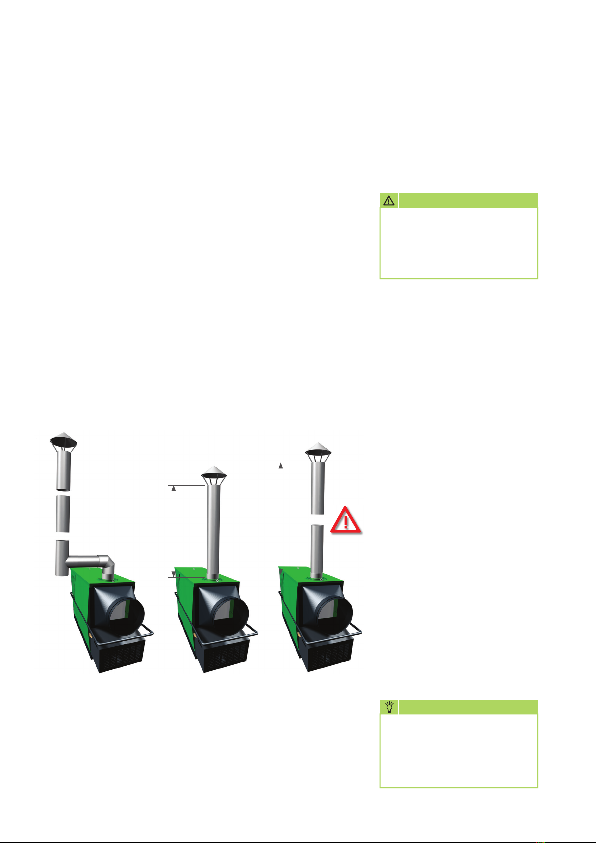
ATTENTION
If a build-up of heat should
occur then the heating
operation will be interrupted
by the STB permanently.
NOTE
Cycled operation
of the forced-air burner with
run times under 5 min. should
certainly be avoided.