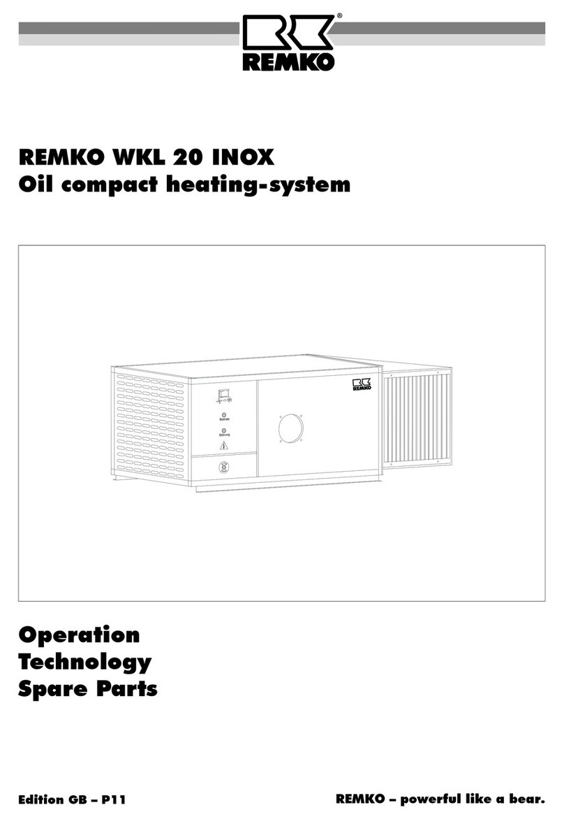
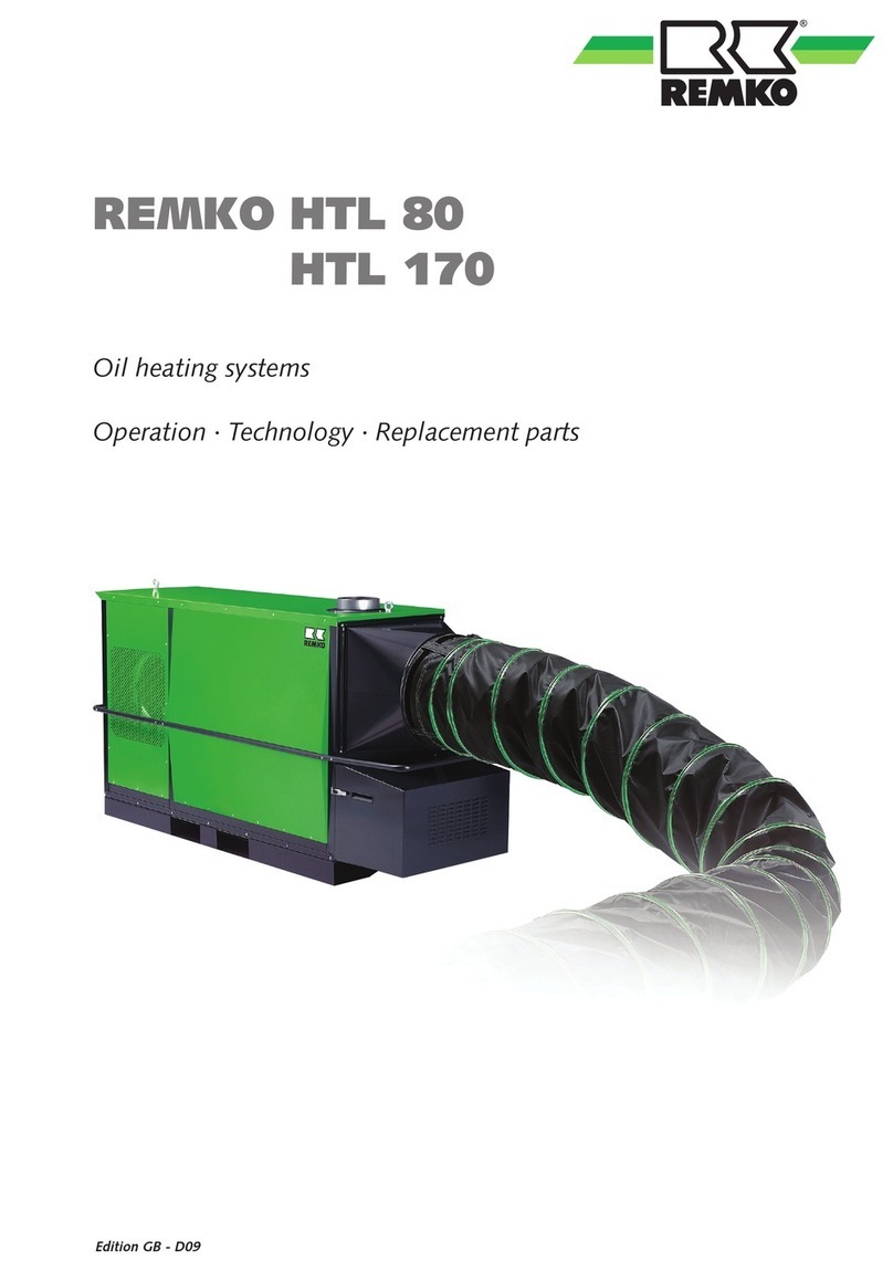
REMKO HTL 400 User manual

Oil-fired Heating Centers
Operation · Technology
REMKO HTL 400
Edition GB – R11


3
Contents
Safety Instructions 4
Description of Device 4
Setting up the Unit 6
Prior to Operation 8
Initial Operation 10
Shutting Down the Unit 11
Maintenance and Service 12
Troubleshooting 14
Proper use 15
Customer Service and Guarantee 15
Environmental Protection and Recycling 15
Wiring diagram 16
Maintenance Log 18
Technical data 19
Made by REMKO
Before commissioning / use of the device, these
operating instructions must be read carefully!
These instructions are a part of the device and must thus
always be kept in the direct vicinity of the assembly site or on
the device itself.
Subject to change; we do not accept liability for errors and typographical errors!

4
REMKO HTL 400
Only approved forced air oil
burners as LE models in
compliance with DIN EN 230
und DIN EN 267 may be used.
IMPORTANT
Never interrupt the mains
connection before the entire
cool-down phase comes to an
end (except in emergency
situations).
IMPORTANT
NOTE
For optimal operation, the
device should not be used
within an environment where
the surrounding temperature is
in excess of 25 °C.
The device is directly fuelled with
EL heating oil or diesel fuel and
designed for fully automatic,
universal and trouble-free
operation.
The device is fitted at the works
with a large volume fuel preheater
and fuel filter. All components are
mounted behind a locking door to
protect them from the
elements
.
The device is operated with a
separate forced air oil burner and is
suitable for outside operation.
The device is fitted with a low
maintenance high performance
fan as well as mounted switching
and controlling device.
The device is designed for two-
stage operation and has an optical
indicator for the individual
operating functions.
The device consists of a stable
frame structure supported on
robust transport runners.
As a guarantee for many years of
operation, particularly in the open
air, the frame structure and cover
panels are constructed from rust
free stainless steel. All internal
construction parts are also
assembled from corrosion-resistant
material.
The device corresponds with the
basic safety and health require-
ments of the pertinent EU
regulations and is easy to operate.
When using the device, always observe the respective local construc-
tion and fire protection ordinances as well as the regulations of
the employers‘ liability insurance association
Description of Device
■
Mobile fuel-tanks may only
be used in compliance with the
“TRBF 210 und 280" technical
regulations for combustible
fluids
■
Possible requirements of
respective local state build-
ing regulations must also be
observed
■
The intake guard grille must
always be free of dirt and loose
objects.
■
Never insert foreign objects into
the device
■
Before all work on the device,
the mains plug must be re
moved from the mains socket
■
Safety devices must never be
short-circuited or disabled
■
The device must only be
operated by persons who have
been trained in their correct
use.
■
The device must be set up
and operated in such a way
that nobody is in any danger
from exhaust gases, hot air or
radiant heat and the danger of
fire is prevented.
■
The device must only be
operated in rooms where there
is an adequate supply of air to
support combustion.
■
Without chimney ducting, the
device must only be operated
within well-ventilated rooms.
The permanent presence of
persons at the set-up site is not
permitted under such circum
stances.
Corresponding prohibition signs
must be posted at the entry
ways.
■
A safety zone of 1.5 m around
the device must be observed,
also for non-flammable objects.
■
The device must only be set
up on a level and non-
flammable surface
■
The device must not be set up
or operated in an environment
where there is a hazard of fire
or explosion
■
All electrical lines of the device
must be protected from dam
age (e.g. due to animals)
■
The device may not be exposed
to a direct water spray e.g. high
pressure hoses etc.
Safety Notices

5
CAUTION
Prior to resetting the safety
temperature cut-out before
resuming operation, it is vital
to identify the possible causes
for it having been triggered.
The thermostat (TR) controls
operation of the fan.
The temperature monitor (TW)
limits the heating output during
operation via the forced air oil
burner.
The safety temperature cut-out
(STB) interrupts the heating
function in the case of extreme
overheating or failure or defect of
the TW.
The red warning lamp
„Overheating“ on the switch cabi-
net lights up.
Resetting the STB is performed
using the „Overheating“ reset
button on the switch cabinet and
is only possible after the device has
cooled down.
The fan motor is controlled by a
thermal overload relay. In the case
of overload of the motor,
operation is interrupted by the
relay and the red warning lamp
“Fan” lights up on the switch
cabinet .
Resetting is performed using the
"fan" reset button on the switch
cabinet.
All electrical components are
additionally protected by circuit
breakers.
Resetting can only be performed
after opening the switch cabinet.
Prior to opening the switch
cabinet, it is vital that the device
is disconnected from the mains
power supply.
Dependent upon the heating
requirement, the operation
described is repeated auto-
matically.
After the device is switched off by
the operating switch or a room
thermostat, the inlet air fan
continues to run for a while to cool
the combustion chamber and heat
exchanger and then turns off auto-
matically. This process may repeat
itself several times.
Monitoring operation
of the device
All functions of the device are
monitored safely and fully auto-
matically by the thermostat of the
three fold combination
controller and the automatic
burner unit (component of the
forced air oil burner).
In the event of irregularities or
extinguishing of the flame, the
device is switched off by the auto-
matic burner unit.
The warning light of the automatic
unit and the red warning lamp
“Burner” light up on the switch
cabinet.
Restarting can only be performed
by means of manually resetting
the automatic burner unit using
the reset button “Burner” on the
switch cabinet.
Suitable locations for
operating the device
As a directly fuelled warm air gen-
erator, the device provides
immediate heat.
It is exclusively used for commer-
cial heating and ventilating
purposes.
The devices are used to heat or
control the temperature of sites
such as e.g.
■
Warehouses
■
Exhibition rooms
■
Fair halls
■
Lightweight construction
buildings
■
Marquees
■
Large building sites
Sequence of functions
When the device is switched on,
the forced air oil burner starts
automatically. This is confirmed by
the green operation lamp
“Heating” on the switch cabinet
lighting up.
When in operation using a room
thermostat, the forced air oil
burner only starts up when heat is
required.
The combustion chamber with
heat exchanger is heated up to the
target temperature of the
temperature monitor (80 to 85
°C).
The thermostat (target
temperature 35 to 40 °C) auto-
matically switches on the inlet air
fan prior to this.
This is confirmed by the green
operation lamp “Fan” on the
switch cabinet lighting up.
Hot air is blown out.

6
REMKO HTL 400
To prevent damage to the
combustion chamber from
the precipitation of dampness
(condensate) during longer
exhaust operation, make sure
that the chimney pipe is fitted
correctly with a condensate
trap.
NOTE
■
An adequate supply of air for
combustion is provided when
e.g.
- the contents of the room in
m3 corresponds to at least
the nominal thermal load in
kW of all heating devices
present in the room and a
natural change of air through
windows and doors is as
sured.
■
Good natural ventilation is
provided when e. g.
- the room volume in m3 cor
responds to at least 30 times
the nominal heat output
in kW of all devices being
operated in the room and a
natural exchange of air
is guaranteed by windows
and doors.
Chimney extraction
In free or open halls, the device
may be used without special ex-
haust extraction.
For the secure expulsion of
exhaust gases however, an
chimney pipe of at least 1 m with
integrated canopy should be used
(accessories), in order to avoid
causing nuisance to persons and
preventing condensation in the
combustion chamber.
When set up internally (closed
rooms) appropriate chimney
extraction is required in
compliance with the regulations
in force.
Setting up the device
When setting up the device, the
requirements of local building
regulations and heating device
ordinances of the respective state
must be observed.
When deciding upon an
operation location at indoor and
outdoor sites, requirements must
be checked in respect of:
■
Fire protection and company
safety
■
The provision of adequate
safety clearance.
■
The function
Room heating, open blown or
ducted, low pressure or high
pressure in the set-up room!
■
General aspects
Heat requirement, room
temperature, nominal air flow
volume, air diffusion, require-
ments in terms of recycled or
fresh air and spatial require-
ments.
■
Chimney extraction
■
Assembly, repair and
maintenance facilities
■
Internal set-up
Relationship between room
volume and nominal heat
output, particularly in the
case of naturally ventilated
rooms!
Setting up
■
Both internally and externally,
the device must be set up
stably on a level, natural
and non-flammable surface and
outside of busy areas e.g. away
from cranes.
■
In the case of a soft surface,
appropriate substructures must
be used such as e.g. squared
timber beneath the transport
runners.
■
The device must be set up
and operated in such a
way that nobody is in any
danger from exhaust fumes and
radiant heat and the danger of
fire is prevented.
■
The device must be set up in
such a way that it does not
constitute a source of danger or
unreasonable nuisance.
Vibrations, oscillations or
noises
■
The device must be set up and
assembled so that it is easily
accessible for repair and
maintenance work.
■
Operating controls, the
incorrect use of which could
lead to dangerous situations,
are to be kept safe from
possible unauthorized access.
■
The device must not be set up
or operated in an environment
where there is a hazard of fire
or explosion
■
The device must only be
operated in rooms
where there is an adequate
supply of air to support com
bustion and the chimneys
are expelled to the outside
CAUTION
When performing all tasks
it must be ensured that the
device is in a stress-free and
horizontal position.

7
■
Secure fastening of the tubes
and pipes at the connection
points must be observed
■
To prevent heat accumulation,
sharp kinks or bends should be
avoided in the tubes
■
Folded spiral-seam tubes should
preferably be used
■
Hot air or plastic tubes should
only be used for straight air
ducting where possible.
■
Plastic tubes must not be
twisted
■
When heating closed rooms
using hot air ducting, back
pressure must not be allowed to
build up.
■
With increased induction
temperature or resistance at
the device air outlet, it is
possible that the forced air oil
burner is switched off briefly by
the temperature monitor (TW).
After reduction of the
temperature the burner will fire
up again automatically!
■
In the case of cycle intervals
that are too short, the length
of the hot air ducting should be
checked.
Electrical connection
■
The electrical connection
of the device must be
performed at a dedicated
supply point with an earth-
leakage circuit breaker in
compliance with VDE
0100 section 55.
■
The power cable required
should be in concordance
with the connected load of the
device and the cable length as
well as the local conditions.
■
Cable extensions must be
suitable and may only be used
if they are completely unrolled
or rolled up.
Hot air diffusion
The device is fitted with a special
high performance radial fan.
This fan is designed to
selectively and effectively transport
the heated air depending upon the
appropriate requirements.
Diffusion of the air is best
performed using pipes or special
hot air or film hoses. The lengths
possible are dependent upon re-
sistance provided by the air
ducting in use.
When using hot air hoses, the
following points must be taken
into consideration:
■
Only use the hot air tubes
approved by us (accessories).
■
The internal overlaps on the
seams of the hot air hoses must
point in the direction of the air
flow.
Fuel supply
An adequate fuel supply must be
maintained on site using appropri-
ately approved safety tanks.
Free flow heating oil must be
available in sufficient supply, also
in the case of low external tem-
peratures. Paraffin formation can
already take place at temperatures
below 5°C.
To avoid this, preventive measures
must be taken such e.g. winter
proof heating oil, a heated oil
tank, insulated oil pipes etc.
Care should also be taken that the
pipe diameter is suitable for the
total resistance, the suction height
and increased viscosity in the case
of lower oil temperatures.
If required, an oil pump should be
used.
It is essential that the suction pipe
at the base of the tank is fitted
with a foot-operated valve.
It should be noted that perfect
functioning of preheated oil is only
effective when the device has been
supplied with power for a long
period prior to starting up.
It is not possible to remove
paraffin that has already separated
prior to preheating of the oil.
Should paraffin have already
formed, thorough cleaning of the
total fuel system is required.
CAUTION
In the event of accumulated
heat, heating operation will
be continuously interrupted by
the STB!
CAUTION
Cycle operation (running times
of less than 5 mins.) of the
forced air oil burner should be
avoided.

8
REMKO HTL 400
■
With increased induction
temperature or resistance at
the device outlet, it is possible
that the forced air oil burner is
switched off briefly by the tem-
perature monitor (TW).
After reduction of the tempera-
ture the burner will fire up
again automatically!
■
In the case of cycle intervals
that are too short , the length
of the hot air ducting should be
checked.
■
To prevent heat
accumulation, sharp edged
bends should be avoided in the
hose guidance. Film hoses
must not be twisted
Air Induction
Using appropriate accessories and/
or connections, the device can be
operated in fresh air, blended air or
recycled air mode.
Induction may only be performed
using stable pipes or similar
suitable air ducting.
After being checked for
fulfilment of the local regula-
tions as well as a check by
authorised, expert personnel,
the forced air burner must be
checked and where appropri-
ate reset in terms of its exhaust
pollution standards.
NOTE
Air Diffusion
The device is fitted with a special
high performance radial fan which
is designed to selectively and
effectively transport the heated air
across long distances.
The diffusion of the air is best per-
formed using pipes or special hot
air or film tubes
■
Use exclusively the hot air
tubes approved by us
(accessories)
■
Attention should be paid to the
flow direction of the tubes!
The internal overlaps on the
seams of the hot air tubes must
point in the direction of the air
flow
■
Secure fastening of the tubes
and pipes at the exhaust and
any connection points used
must be observed
■
Only suitable air diffusers or
those approved by us may be
used
■
When heating closed rooms
using hoses, back pressure must
not be allowed to build up
Before commissioning, the device
should be checked for noticeable
defects of the operating and safety
devices, as well as for proper set-
up and correct electrical
connection.
The following points must be
taken into consideration:
■
It must be assured that the
chimneys can be properly
expelled
■
The device must be
set up stably
■
An adequate supply of inlet air
for combustion must be assured
■
Check that there is no
physical restriction on air intake
and air emission
■
Avoid excessively high or low
pressure in the operation
location
■
Assure and adequate supply
of fuel which also complies to
local requirements
■
Only use clean EL heating oil or
diesel fuel
Do not use biodiesel!
■
It is essential that the suction
pipe at the base of the
tank is fitted with a foot-
operated valve
■
A safety zone of 1.5 m around
the device must be observed,
also for non-flammable objects
Prior to Operation
The hot air tubes may only be
used fully extended and with-
out kinks.
IMPORTANT
Cycle operation of the forced
air burner of less than 5 mins.
should be avoided at all costs.
NOTE
The maximum air intake
temperature may not exceed
30 °C
NOTE
CAUTION
In the event of accumulated
heat, heating operation will
be continuously interrupted by
the STB!

9
NOTE
Intake air ducting must always
be of sound construction (no
unstable tubes).
If the thermal overload relay
is operated in the „Automatic
reset“ setting, damage to the
motor cannot be excluded.
This renders any guarantee
null and void!
NOTE
Measuring nominal current
and current consumption
Following installation of the air
ducting on induction and air outlet
sides, the following checks should
always be carried out by by expert
personnel only, to ensure perfect
functioning of the fan.
1. For purposes of precise
measurement, all air ducting on
induction and air outlet sides
(areas of resistance) must be
fitted to the device and any
exhaust guard grille opened.
2. The mains voltage available
must be checked for correct
ness. Drops in voltage must not
be allowed during operation.
3. Note that the nominal current
(Ampere) stated on the type
plate of the motor must not
be exceeded in any mode
of operation.
4. The fan stages 1 and 2 each
have a separate thermal over
load relay and must be set
accordingly.
Setting the thermal overload
relay
1. In order to preclude errors in
measurement each phase
conductor and fan stage must
be tested separately.
2. The setting of the thermal over
load relay should be performed
as follows:
Stage 1 = 6.7 A
Stage 2 = 17.0 A
3. The function of the thermal
overload relay and its
setting values must be tested
by the simulation of a missing
phase conductor.
e.g. by switching off a circuit
breaker
4. With correct function and
setting of the thermal overload
relay, it should switch off after
approx. 30 seconds.
5. All measurements and tests
must be performed separately
for each fan stage
Excessive current
consumption
If the motor is using too much
current, despite correct electrical
connection and adequate voltage
supply, the thermal overcurrent trip
may not under any circumstances
be set higher or short-circuited.
■
Appropriate measures must
be taken such as checking or
adjusting the outside
induction and air outlet
diameters and lengths.
CAUTION
Never interrupt the mains
connection before the entire
cool-down phase comes to an
end. Damage caused to the
device by overheating renders
the guarantee null and void.
CAUTION
The thermal overload relay
may only be operated in the
„Manual reset“ setting. The
relay must not switch itself on
again after the cooling down
process.

10
REMKO HTL 400
Starting the device
Operation and monitoring of the
machine must be assigned to a
person who has been adequate
training.
Open the locking door at the rear
of the device.
Check that the operating switch on
the switch cabinet is set to the
“0” position (off).
Connecting the devices to the
power supply
The 400V/3~N electrical connec-
tion is made using a supplied
32 A CEE appliance coupler.
1. The device must be connected
to a correctly installed power
socket via a suitable extension
cable. 400V/3~N/50Hz
Heating without room
thermostat
The device works in continuous
operation.
1. Connect the jumper plug 2
supplied to the thermostat
socket 1 on the device / switch
cabinet.
2. Turn the operating switch to
the required operation position
“1” (low heating stage) or
“2” (high heating stage) .
NOTE
As standard, the devices are
equipped with a an automatic
rotation direction monitor for
the fan motor.
NOTE
The electrical connection of
the device must be performed
at a dedicated supply point
with an earth-leakage circuit
breaker in compliance with
VDE 0100 section 55.
�
2
1
3. Open all closures in the fuel
supply. During initial
commissioning, air in the
supply lines can lead to a fault
shutdown of the
burner.
2. Each phase can be checked for
correctness using the phase test
selector switch.
Ventilation
The equipment can be used for air
circulation or ventilation purposes.
1. Turn the operating switch to
the required operation position
“1” (low ventilation stage) or
“2” (high ventilation stage).
In these switch positions, the inlet
fan will run in continuous mode.
In these operational modes,
neither thermostatic nor heating
operation are possible.
Commissioning
Control panel / switch cabinet
All components are protected from the elements and unauthorized
operation behind the locking door above the fan.
CAUTION
Cable extensions must
be suitable and may only
be used if they are completely
unrolled or rolled up..

11
NOTE
After all adjustment tasks the
doors must be closed.
In order to prevent
unauthorized operation, the
doors should also be locked.
The inlet fan continues to run
to cool the combustion
chamber and the heat ex-
changer and does not switch
off until later. The fan may re-
start several times until finally
switching off.
Never interrupt the mains
connection before the entire
cool-down phase comes to an
end (except in emergency
situations).
Damage caused to the device
by overheating renders the
guarantee null and void.
NOTE
4. In the case of longer down
times, lock the closing lid of
the exhaust connection.
Shutting Down the Unit
Heating with a room
thermostat (accessories)
The devices operate fully auto-
matically depending on the room
temperature.
1. Remove jumper plug 2.
2. Connect plug 3 of the room
thermostat 4 to the thermostat
socket 1 at the switch cabinet.
3. Place the room thermostat 4 at
a suitable location in the room.
The thermostat sensor must not
be within the hot air stream
and should also not be placed
on a cold floor.
4. Set the required temperature on
the room thermostat 4.
5. Turn the operating switch to the
required operation position
“1” (low heating stage) or
“2” (high heating stage).
If heat is required and after a brief
initial ventilation of the burner the
device switches on and continues
to run completely automatically.
1. Turn the operating switch to
the „0“ position (off).
2. Close off the
fuel supply at
the device and
oil tank.
3. In case of longer downtimes,
disconnect the device from the
power supply.
4
3
1

12
REMKO HTL 400
Cleaning tasks
After every heating period or inde-
pendent of the previous operating
conditions, the complete equip-
ment including the heat exchanger,
combustion chamber and burner
must be cleaned of dust and dirt.
Check parts subject to wear such
as e.g. chimney suppressors, oil fil-
ter inserts and oil nozzles are to be
checked and replaced if necessary.
Cleaning the heat exchanger
1. Set the operating switch to the
„0“ position (off) and unplug
the power supply.
2. Disassemble the air outlet gas
connection.
3. Remove the inspection cover
and extract the chimney sup-
pressors.
4.
Clean the chimney passages.
5. Clean the chimney gas sup-
pressors and replace damaged
chimney suppressors where
necessary.
6. Check the seals of the inspec-
tion plate and replace damaged
seals where necessary.
7. After maintenance, reassemble
all parts carefully in reverse
order.
Inspection cover
Make sure that the seals of the
inspection cover are positioned
correctly.
When reassembling the inspection
cover, ensure that all fixing screws
are uniformly tightened.
Fixing screws that are not tighte-
ned uniformly can cause result in
leaks.
The regular care and observance of
some basic prerequisites guarantee
malfunction-free operation and a
long service life of the device.
Maintenance and Care
■
Keep the device free of dust
and any deposits of dirt
■
Only clean the device with a dry
or damp cloth
■
Do not apply any direct water
spray
e.g. high pressure hoses etc.
■
Do not use abrasive or cleaning
solutions containing solvents
■
Only use appropriate cleaning
materials even in the case of
heavy soiling
■
Only use clean EL heating oil or
diesel fuel.
Pay attention to possible paraf-
fin formation!
■
Check the fuel filter(s) at regular
intervals for dirt. Soiled filters
must be replaced
■
Check the device for mechani-
cal damage and have defective
parts replaced professionally.
■
Check the fan blades and
combustion chamber for dirt
regularly and clean them where
necessary
■
Examine on site fuel containers
regularly for contamination or
foreign bodies and clean them
where necessary
■
Check the fan belt tension and
condition regularly. The depth
of indentation of the fan belt
should be approx. 10 mm
(thumb‘s width)
■
Check the safety devices regu-
larly for correct function
■
Keep the sensors of the safety
devices free from dust and dirt
■
Have the forced air burner
checked regularly by authorised
expert personnel in terms of its
exhaust pollution standards.
For reasons of safety we recom-
mend a maintenance contract
■
Maintenance and cleaning
intervals must be maintained for
reasons of operational safety
IMPORTANT
Before all work on the device,
the mains plug must be remo-
ved from the mains socket.
Adjustment and maintenance
tasks may be performed only
by authorised expert
personnel!
NOTE

13
Cleaning the combustion chamber
1. Set the operating switch to the
„0“ position (off) and unplug
the power supply.
2. Open the locking door at the
front of the device.
3. Unscrew the fuel filter including
the fuel lines and pull the roset-
te from the burner.
4. Release the lower 2 fastening
screws on the burner flange 6.
5. Release the clamping screw 7
on the burner flange 6 and pull
the burner out forwards.
70
6
7
Following all work on the
device, an electrical safety test
in accordance with VDE 0701
must be carried out.
CAUTION
Additional maintenance hints
■
All tasks should only be per-
formed by authorised, expert
personnel with the appropriate
tools and parts.
A log must be produced and
kept by the operator.
■
It is vital that the forced air he-
ater is serviced and adjusted by
authorised, expert personnel.
Assembling the burner flange and
the burner
1. Check the flange seal and re-
place it if necessary.
2. Attach the burner flange with
the four fastening screws to the
unit housing.
Pay attention to the „OBEN“
(UP, HAUT) label!
3. Tighten the 2 upper fastening
screws.
4. Tighten the 2 lower fastening
screws only lightly so that the
burner flange can be pulled
together.
5. Slide the flame tube of the bur-
ner into the burner flange.
Observe the measurement X in
the figure!
6. Attach the flame tube firmly to
the flange with clamping screw
7 while lifting the burner
slightly (3° incline).
7. Finally, tighten the lower 2
fastening screws.
8. Reassemble the fuel filter and
lines and check for tightness.
NOTE
Flue gas loss must be restricted
in accordance with section 11
of the small heating device
ordinance (1.BImSchV).
6. Place the burner and the fuel
filter carefully beside the device.
7. Disassemble the burner flange 6.
8. Take care not to damage the
flange seal.
Damaged flange seals can re-
sult in incorrect air induction.
9. Clean the combustion cham-
ber with a vacuum cleaner
through the burner opening.
A special chamber cleaning set
is available as an accessory to
the REMKO industrial vacuum
cleaner.
NOTE
After all adjustment tasks the
doors must be closed.
In order to prevent unautho-
rized operation, the doors
should also be locked.

14
REMKO HTL 400
IMPORTANT
Before all work on the device,
the mains plug must be remo-
ved from the mains socket.
The device does not start
1. Check the power supply con-
nection. 400 V/3~N/50Hz.
2. Turn the operating switch to
the „Heating“ position(off).
3. The „Operation“ pilot lamp on
the control panel must be lit up.
4. Check the jumper plug or the
plug of the room thermostat for
correct fit and contact.
5. Check the setting of the room
thermostat. The temperature
set must be higher than the
room temperature.
6. Check whether the safety tem-
perature cut-out (STB) has been
triggered.
For this, check the indicator on
the control panel.
Troubleshooting
CAUTION
Repair work on the electrical
installation and on the burner
may be carried out only by
authorised, expert personnel
for safety-technical reasons.
Forced air burner and
energy supply
1. Check the oil filter(s) for dirt.
Exchange soiled filters.
2. Check that the closing tap on
the oil filter is open.
3. Check that there is an adequate
supply of fuel.
4. Check the heating oil for paraf-
fin formation.
This can occur at temperatures
as low as 5 °C !
5. Check the oil lines for damage.
6. Check the sensors and capillary
tubes of the safety devices for
damage or dirt.
7. Check that the temperature
monitor (TW) for correct func-
tion using appropriate means.
8. Check the forced air burner for
possible soiling of the nozzle,
blockage, filters etc.
The inlet air fan does not
actuate.
1. Check the fan for smooth
running.
2. Check the circuit breaker in the
switch cabinet.
3. Check whether the motor pro-
tection relay has in the switch
cabinet has been triggered.
4. Check the thermostat (TR) for
correct function using appropri-
ate means.
Important information about
resetting the burner
■
If the burner switches off again
because of a fault during
starting, it may only be reset
after waiting 5 mins. approx.
■
Resetting again should be strict-
ly avoided. There is a danger of
explosion.
7. Prior to resetting the STB, make
sure to analyse the causes and
eradicate them.
The following causes can be
possible:
- The equipment was unable to
cool down, as the power supply
was interrupted.
- Too high air outlet temperature
because of incorrect air diffusion
in hose mode.
- Air cannot flow freely in or out.
8. Check whether the „Burner
fault“ pilot lamp has lit up on
the control panel. If so, reset
the automatic burner.
9. Turn the operating switch to
the „Ventilation“ setting.
If the inlet fan runs, it may be
necessary to seek the fault in
the burner area..

15
Because of their means of design
and construction, the devices are
solely suitable for heating and
ventilation purposes in industrial
or commercial premises (not room
heating on private premises).
The devices must be exclusively
serviced by appropriately trained
staff.
In the case on non-observance of
the manufacturer‘s instructions,
the local legal specifications in re-
spect of set-up the device or inde-
pendently performed modifications
to the equipment the manufacture
assumes no liability for possible
damage caused.
Customer Service and
Guarantee
Environment Pro-
tection and Recycling
Disposal of packaging
When disposing of packaging
material, please consider the
environment. Our equipment
is packed carefully for transport
and supplied in stable cardboard
packaging on a wooden palette if
required. The packaging materials
are environmentally friendly and
can be reused. With the reuse of
packaging material, you make a
valuable contribution to the reduc-
tion of waste and the preservation
of raw materials.
You should thus dispose of the
packaging material at the corres-
ponding disposal sites.
Disposal of the old device
Manufacture of our equipment is
subject to constant quality control.
Only high-quality materials that
are recyclable to a great extent are
used.
You also contribute to environ-
mental protection by guaranteeing
that your old device is disposed
of in an environmentally friendly
manner.
For this reason, bring the old
device only to an authorised recy-
cling company or to a correspon-
ding disposal site.
A prerequisite for possible claims
under guarantee is that the custo-
mer/his supplier have returned the
„guarantee certificate“ enclosed
with the device promptly after
purchasing the unit and putting it
into operation to REMKO GmbH &
Co KG.
The device was tested several
times at the factory for perfect
function.
If any malfunctions should occur,
however, which cannot be elimina-
ted by trouble shooting measures
performed by the operator, please
consult your dealer or contract
partner.
Proper use
Any other operation other
than that described in these
operating instructions is not
permitted.
Non observance renders all
claims for liability and guaran-
tees null and void.
NOTE
Adjustment and maintenance
tasks may be performed only
by authorised expert personnel.
NOTE

16
REMKO HTL 400
We reserve the right to make changes in dimensions and design in the interest of technical advance.
Wiring diagram

17
When ordering spare parts, always list the EDP no. as well as the device no. and device type (see the type plate)!
Wiring diagram

18
REMKO HTL 400
Maintenance Log
1. Date: ..............
..............................
Signature
2. Date: ..............
..............................
Signature
3. Date: ..............
..............................
Signature
4. Date: ..............
..............................
Signature
5. Date: ..............
..............................
Signature
6. Date: ..............
..............................
Signature
7. Date: ..............
..............................
Signature
8. Date: ..............
..............................
Signature
9. Date: ..............
..............................
Signature
10. Date: ............
..............................
Signature
11. Date: ............
..............................
Signature
12. Date: ............
..............................
Signature
13. Date: ............
..............................
Signature
14. Date: ............
..............................
Signature
15. Date: ............
..............................
Signature
16. Date: ............
..............................
Signature
17. Date: ............
..............................
Signature
18. Date: ............
..............................
Signature
19. Date: ............
..............................
Signature
20. Date: ............
..............................
Signature
✍
*) The forced air burner must only be maintained and set by authorised expert personnel in accordance with legal specifications
(1. BImSchV.). An appropriate test log must be kept.
Maintenance work may only be performed on the forced air burner by authorised expert personnel
in accordance with legal specifications.
Device type: .................................. Device number: ...................................
1 2 3 4 5 6 7 8 9 10 11 12 13 14 15 16 17 18 19 20
Clean unit – surface –
Clean unit – inside –
Clean fan
Clean combustion chamber
Clean heat exchanger
Replace chimney suppressor
Replace inspection cover seals
Replace fuel filter
Check safety devices
Check protection devices
Check device for damage
Electric safety inspections
Burner maintenance *)
Test run
Remarks: .............................................................................................................................................................
.............................................................................................................................................................................
.............................................................................................................................................................................

19
Technical data
We reserve the right to make changes in dimensions and design in the interest of technical advance.
1) at ∆t 45K / 1.2 kg/m3 (free flowing)
2) The nozzle sizes and pump pressures stated are based on test bed results.
The oil throughput was stated in litres.
Because of product-specific nozzle and pressure tolerances as well as oil temperature, the figures stated should only be viewed
as guidelines.
Series HTL 400
Nom. heat load max.2. Stage kW 385
Nom. heat load max. 1. Stage kW 270
Nom. heat output max. 2. Stage kW 350
Nom. heat output max 1. Stage kW 245
Ventilating performance max. 1) 2. Stage m3/h 25000
Ventilating performance max. 1) 1. Stage m3/h 16600
Pressure (max. total.) 2. Stage Pa 1000
Pressure (max. total.) 1. Stage Pa 500
Fuel EL heating oil or diesel
Fuel consumption max. 2. Stage l/h 39.0
Fuel consumption max. 1. Stage l/h 28.0
Nozzle (Danfoss) 80° H 2) USG 6.0
Pump pressure, approx. 2) 2. Stage bar 22
Pump pressure, approx. 2) 1. Stage bar 11
Voltage supply V 400 3~N
Frequency Hz 50
Elect. current consumption max. 2. Stage A 20.5
Elect. current consumption max. 1. Stage A 10.5
Elect. power consumption max. 2. Stage kW 9.1
Elect. power consumption max. 1. Stage kW 3.9
Fuse protection (on site) A 32
chimney connection ø mm 300
Dimensions: Length mm 3850
Width mm 1200
Height mm 1900
Weight kg 1600

Subject to technical changes, no responsibility is accepted for the accuracy of this information.
REMKO EUROPE-WIDE
… and somewhere near to you!
Benefit from our experience and advice
REMKO GmbH & Co. KG
Air Conditioning and Heating Technology
Im Seelenkamp 12 · 32791 Lage, Germany
P.O. Box 1827 · 32777 Lage, Germany
Telephone +49 5232 606-0
Telefax +49 5232 606-260
E-mail [email protected]
Internet www.remko.de
Consulting
Through intensive training, we make
sure the expert knowledge of our con-
sultants is always up-to-date. This has
given us the reputation of being more
than just a good, reliable supplier:
REMKO, a partner that helps solve
problems.
Sales
REMKO not only provides an extensive
sales network in Germany and abroad,
but also unusually highly qualified sales
experts.
REMKO sales representatives are more
than just salespeople: above all they
have to be consultants: to our customers
in the field of air conditioning and heat-
ing technology.
Customer Service
Our equipment runs precisely and reli-
ably. If a malfunction appears, however,
REMKO Customer Care is on the job.
Our extensive network of experienced
dealers guarantees you constant, short-
term, and reliable service.
Table of contents
Other REMKO Heating System manuals