Renaissance RB5C4848LR User manual

Rev C Date: 07.19.2006
PN 99515
R
888 Porter Rd. Muskegon, MI 9 1 Phone: 231.798.8888 Fax: 231.798. 960 www.structuralconcepts.com
READ AND SAVE THESE INSTRUCTIONS
OPEN REFRIGERATED SELF-SERVICE MERCHANDISER
Model RB5C 8 8LR 8”L* x 38 1/8”D** x 7 1/ ”H
Model RB5C59 8LR 56”L* x 38 1/8”D** x 7 1/ ”H
Model RB5C77 8LR 77”L* x 38 1/8”D** x 7 1/ ”H
Model RB5C 8 8RR 8”L* x 38 1/8”D** x 7 1/ ”H
Model RB5C59 8RR 56”L* x 38 1/8”D** x 7 1/ ”H
Model RB5C77 8RR 77”L* x 38 1/8”D** x 7 1/ ”H
*Includes end panels.
**Without Package Ledge or Cutting Board
SERVICE REFRIGERATED / NON-REFRIGERATED MERCHANDISER
OPERATING
MANUAL
L:\Inst & Oper Man\Renaissance\RB5C(L) 8LR&RR Oper Man 99515.pub

2
TABLE OF CONTENTS
OVERVIEW AND WARNINGS .. .…………………………..…………………..…….………….....…..
MERCHANDISER SET-UP ………….. …..….…………………...………...…..………………………
START-UP AND OPERATION ...…………….. …..….…………………...………...…..………………
MAINTENANCE FUNDAMENTALS ……………………………………………………………..………
ELECTRICAL FUNDAMENTALS ……………. …..….…………………...………...…..………………
REFRIGERATION FUNDAMENTALS …………………….………………………………………..…...
TECHNICAL DATA ………………………………………………………………………………….……
ILLUSTRATED PARTS BREAKDOWN …………………….…………………………………………...
PARTS LIST ..………………………………………………………………………………………………
TROUBLESHOOTING ……………………………………………………………………………………
WIRING DIAGRAM RB5C (48/5 /77) 48 LR & RR Units SELF CONTAINED ………………….….
WIRING DIAGRAM RB5C (48/5 /77) 48 LR & RR Units REMOTE …………...………………….…
CLEANING SCHEDULE ..…………………………………………………………...……………………
JOHNSON CONTROL ALARM and FAULT CODES …………………………..……………………..
JOHNSON CONTROL PROGRAMMING ………………….………………………………………..….
WARRANTY ..………………...……………………………………………………..……………………..
TECHNICAL SERVICE .…………..……………………………………………….……………….…..…
3
4
5
6
8
11
12
15
17
18
1
20
21
22
24
25
R
888 Porter Rd. Muskegon, MI 9 1 Phone: 231.798.8888 Fax: 231.798. 960 www.structuralconcepts.com

3
R
888 Porter Rd. Muskegon, MI 9 1 Phone: 231.798.8888 Fax: 231.798. 960 www.structuralconcepts.com
OVERVIEW AND WARNINGS
OVERVIEW
• *The Structural Concepts Renaissance refrigerated service cases are designed to
merchandise packaged bakery products at 5° Celsius / 41° Fahrenheit or less product
temperatures.
• These cases should be installed and operated according to the following instructions to
insure proper performance.
• This unit is designed for the display of products in ambient store conditions where
temperatures and humidity are maintained at a maximum of 24° C / 75° F and 55% relative
humidity.
WARNING
Risk of Electric Shock.
Disconnect Power Before Servicing Unit
WARNING
ELECTRICAL
HAZARD
WARNING
Hazardous Moving Parts.
Do Not Operate unit with covers removed.
Fan blades may be exposed when deck panel is removed. Disconnect
power before removing deck panel.
CAUTION
Lamps have been treated to resist breakage and must be replaced with a
similarly treated lamp.
WARNING
Evaporator Tray is Hot
WARNING
KEEP HANDS
CLEAR
WARNING
HOT
SURFACE
CAUTION

R
888 Porter Rd. Muskegon, MI 9 1 Phone: 231.798.8888 Fax: 231.798. 960 www.structuralconcepts.com
SET-UP
Merchandiser Set-Up
• Mobile Units (Cases with Casters)
• For your safety, the equipment is fur
nished with a properly grounded cord
connector. Do not attempt to defeat the
grounded connector.
• Plug cord into a certified electrical outlet
with ground.
• Stationary Units
• Self-contained refrigeration.
Note: Servicing to be accomplished by
refrigeration / electrical contractor.
• Removing the rear grill will expose ac-
cess to the a 3” service opening in the
base adjacent to a junction box.
• Electrical 120v leads are provided in the
junction box.
• Remote refrigeration system.
Note: Servicing to be accomplished by
refrigeration / electrical contractor.
• Removing the rear grill will expose ac-
cess to the a 3” service opening in the
base adjacent to a junction box.
• 120v Electrical leads are provided in the
junction box.
• Refrigeration stub up connections are
provided inside the case, from the rear
and in back of the electrical box.
• To facilitate maintenance see electrical
section for electrical box removal.
4
Evaporator Stub Ups 3” Service Access
Rear Grill

R
888 Porter Rd. Muskegon, MI 9 1 Phone: 231.798.8888 Fax: 231.798. 960 www.structuralconcepts.com
START-UP AND OPERATION
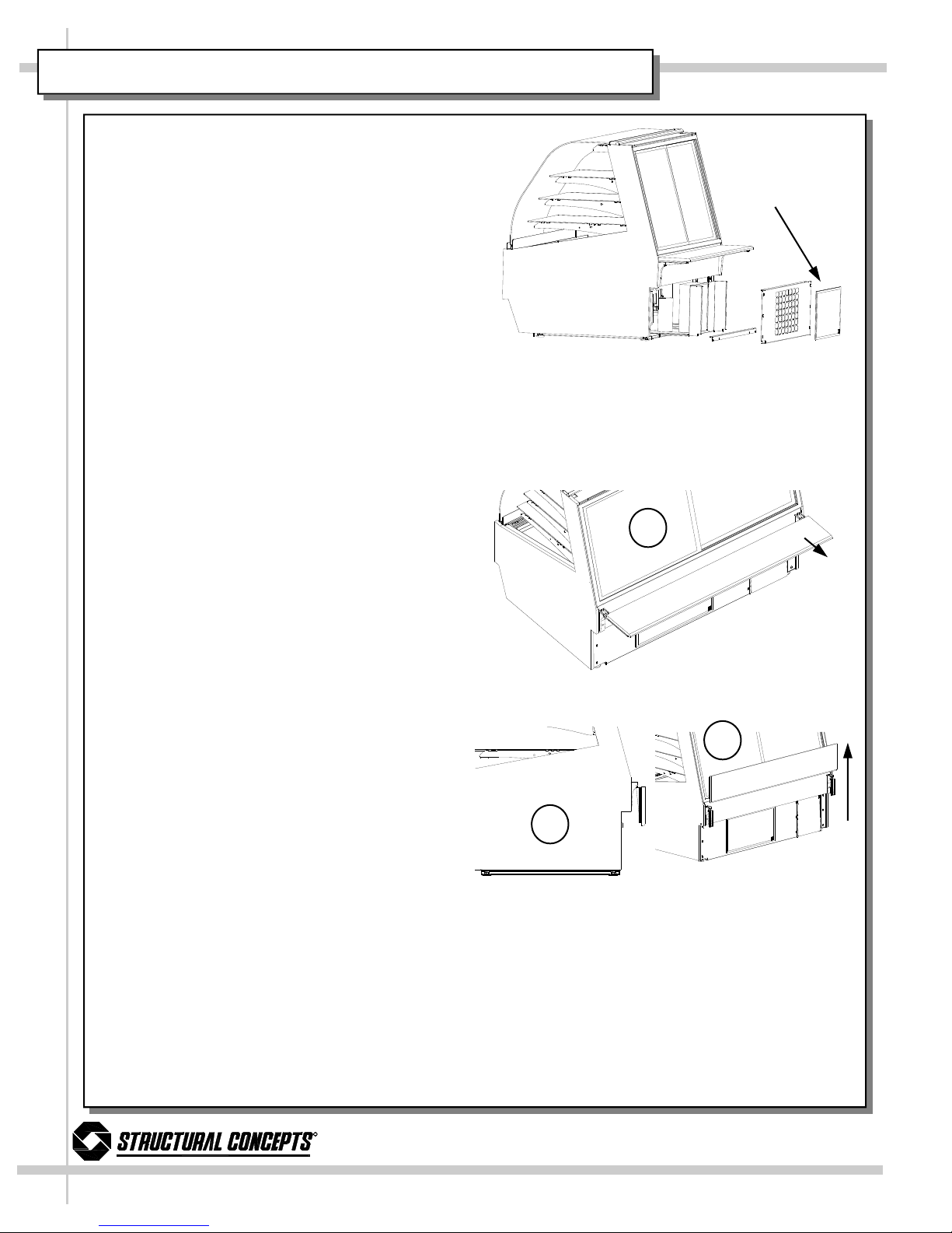
Raise the Curved Glass
• To raise the front curved glass, grab the lift
handle extrusion on the bottom edge of the
front curved glass and lift up.
• Gas cylinders hold the glass open for hands
free access to the interior of the case.
Merchandiser Start-Up
• Turn on the main power. Switch is on the
control panel at the rear right hand side of
base. Supply power will start evaporator coil
fan(s), the front fan and the evaporator/
condensate pan. It will supply power to the
light switch and thermostat, (self-contained
units).
• From the front of the case, raise the deck
pans and check to see that the coil fans are
all functioning properly.
• On the top of the front panel a register di-
rects air flow provided by the front fans,
(front air flow is to prevent condensation
from forming on the curved glass). Check
across the top of the front panel to see if air
is discharging across the entire front of the
case.
• Turn on the lights. Light switch is in the rear
control panel. First time lighting may require
a short warm up period for the bulbs. Slightly
dim or a flickering of new bulbs is normal. If
lights do not turn on, check all of the race-
way plugs. The lighting is wired in series so
all lights must be plugged in or recepta-
cles capped in order for the case to light.
Temperature Settings
The case temperature is set at the factory, as
determined by the case size. The temperature is
controlled by a thermostat. If a temperature
setting change is required, follow the Johnson
Control Quick Reference page 14 of this man-
ual
5
Main Power
Thermostat
Lights
Lift Handle
Front Curved Glass
Deck Pan
Coil Fan
Front Fan
Register

6
R
888 Porter Rd. Muskegon, MI 9 1 Phone: 231.798.8888 Fax: 231.798. 960 www.structuralconcepts.com
MAINTENANCE FUNDAMENTALS
• Preventive Maintenance should be per
formed every 30 days unless conditions
warrant a more frequent replacement cy
cle.
Air Filter
• Magnetic strips attached to the filter adhere
the filter to the rear grill.
• The nylon mesh filter can be cleaned by rins-
ing thoroughly with water against the air flow
direction. A mild detergent removes smoke/
grease stains.
Rear Ledge Removal
1. Pull ledge back to stops.
2. Rotate down to the vertical position.
3. From the shelf’s lowered position (as indi-
cated at right), lift from bottom edge upward
to disengage shelf track from bracket.
Front Panel Removal
• Refer to front fan access in the electrical
fundamentals.
Under Case Cleaning
• Note: Refer to Evaporator Pan Access/
Removal in electrical fundamentals.
• Remove rear grill, use vacuum with hose at-
tachment to clean under case.
• Under case cleaning is accessible by hand
or 1 1/2 inch diameter cleaning tool such as
a vacuum hose.
Air Filter
1
2
3

7
R
888 Porter Rd. Muskegon, MI 9 1 Phone: 231.798.8888 Fax: 231.798. 960 www.structuralconcepts.com
MAINTENANCE FUNDAMENTALS
Shelf Assembly Removal
• Raise the front curved glass.
• Remove and carefully set aside glass or wire
shelves.
• For lighted shelving, unplug the light cord
and detach from the rear shelf support.
• Slide light assembly back to unlock, then ro-
tate up to separate from brackets.
• Slide rear support back to unlock and rotate
up to separate from brackets.
• Remove brackets. Note, it may be neces-
sary to remove the nylon shipping
bracket retainer. Pliers will be required to
accomplish this task.
Light Fixtures
Light fixtures can be located on the underside of
each shelf assembly and at the top inside of
case.
Removal of lamp:
• Rotate lamp (1/4 turn) so that pins are
aligned with socket slots and remove bulb.
Installation of lamp:
• Align pins with slots in sockets.
• Insert pins into socket and rotate 1/4 turn to
secure pin contacts in socket.
Removing the Rear Doors
• Note: Doors are not interchangeable.
There is an inner and outer door. The outer
must be removed first and replaced last.
• The outer door, is the right hand door (from
the service side or rear of the case). It can
be identified by a stop located at the lower
right hand corner to the inside of the case.
• Move the doors toward the center of the
case.
• Individually lift each door up toward the top
of the case and pivot the bottom of the door
out.
• Reverse to install.
Cap
Plug
Receptacle
Rear Doors
Bracket Retainers
Light Assembly
Shelf Brackets Rear Shelf Support
Glass Shelves

8
R
888 Porter Rd. Muskegon, MI 9 1 Phone: 231.798.8888 Fax: 231.798. 960 www.structuralconcepts.com
ELECTRICAL FUNDAMENTALS
Warning, disconnect power before providing
maintenance and service to unit.
Ballast Access/Removal
• Assembly or disassembly and servicing
to be accomplished by licensed electrical
contractor.
• Remove the rear grill by removing the six
screws located on both sides of the grill.
• Remove the control panel by removing the
three remaining screws located on the right
side of the panel.
• Release quick disconnect from wire har-
ness.
• Remove two nuts from both end mounting
flanges.
Electrical Box Access/Removal
• Assembly or disassembly and servicing
to be accomplished by licensed electrical
contractor.
• Remove the rear grill by removing the six
screws located on both sides of the grill.
• Remove the control panel by removing the
three remaining screws located on the right
side of the panel.
• Remove the electrical box by removing the
four screws located inside and at the top of
the box.
Evaporator Pan Access/Removal
• Assembly or disassembly and servicing
to be accomplished by licensed electrical
contractor.
• Turn off main power and allow evaporator
pan to cool.
• Remove the rear grill by removing the six
screws located on both sides of the grill.
• Check temperature of pan prior to han-
dling.
• Withdraw evaporator pan from the right side
behind electrical box.
• Disconnect evaporator pan power cord from
receptacle at the pan.
• Empty evaporator pan contents into a suit-
able container.
Rear Grill
Elect. Box Screws
Ballast
Control Panel
Evaporator Pan

R
888 Porter Rd. Muskegon, MI 9 1 Phone: 231.798.8888 Fax: 231.798. 960 www.structuralconcepts.com
ELECTRICAL FUNDAMENTALS
Warning, disconnect power before provid-
ing maintenance and service to unit.
Evaporator Fan Access
• Raise the front curved glass.
• Shelving can be removed to facilitate main-
tenance
• Turn off the electrical power at main
power switch if servicing fans.
• Remove deck pans to access coil fans.
• Remove mounting screws from fan assem-
bly to separate fan from shroud.
Deck Pan
Coil Fan
Lower Front Panel
Upper Front Panel Assy.
Front Condensate Fan
Fan Shroud Flange Screws

10
R
888 Porter Rd. Muskegon, MI 9 1 Phone: 231.798.8888 Fax: 231.798. 960 www.structuralconcepts.com
ELECTRICAL FUNDAMENTALS
Warning, disconnect power before providing
maintenance and service to unit.
Front Fan Access
The front fans supply air flow to the top of the
front panel louvers. This air flow is to eliminate
any condensation formed on the face of the
curved glass.
• Fan/s are located behind the front panels.
• Turn off the main electrical power at
main power switch if servicing fans.
• Remove the lower front panel.
• Remove screws from the lower flange at
the base of the unit.
• Remove screws from the upper flange
of the lower front panel, located behind
the lower edge of the upper front panel.
• Remove the upper front panel.
• Remove screws from the lower flange of
the plenum at the base of the unit.
• Remove screws from the front panel
support brackets.
• Raise the front curved glass.
• From inside the case remove screws
from the upper edge only of the deck
support & glass stop.
• Pull entire assembly forward and care-
fully set aside.
• Remove mounting screws from fan as-
sembly to separate fan from shroud.
Lower Front Panel Screws Plenum Screws
Bracket Screws
Deck Support & Glass Stop Screws

11
R
888 Porter Rd. Muskegon, MI 9 1 Phone: 231.798.8888 Fax: 231.798. 960 www.structuralconcepts.com
REFRIGERATION FUNDAMENTALS
Temperature Settings
• Assembly or disassembly and servicing
to be accomplished by licensed
electrical / refrigeration contractor.
• The case temperature is set at the factory,
as determined by the case size.
Refrigeration: Access, Connections &
Servicing
• Assembly or disassembly and servicing
to be accomplished by licensed
refrigeration contractor.
• Service connections are located on the
compressor / condenser assembly.
• Refrigerant lines are flexible to facilitate
rear access maintenance to condenser.
• Plastic glides are mounted to the unit base
to assist in sliding the condenser out for
access.
• Remove the rear grill by removing the six
screws located on both sides of the grill.
• Remove structural stiffener by removing the
four screws located on the bottom edge of
the base.
• Withdraw the unit using pull flanges on
condenser frame.
Rear Grill
Stiffener
Condenser Frame
Filter

12
TECHNICAL DATA
R
888 Porter Rd. Muskegon, MI 9 1 Phone: 231.798.8888 Fax: 231.798. 960 www.structuralconcepts.com
Electrical Ratings
RB5C4848R RB5C5 48R RB5C7748R
Self-Contained
Incoming Supply 120/1/60 120/1/60 120/1/60
Min. Circuit Amps 15 15.0 15.0
Amps .58 11.03 11.03
Watts 1150 1324 1324
Hook-Up Leads or Cord w/
Nema 5-15 P
Leads or Cord w/
Nema 5-15 P
Leads or Cord w/
Nema 5-15 P
Electrical Controller
Electrical Control-
ler
Electrical Control-
ler
Electrical Controller
Lighting
RB5C4848R RB5C5 48R RB5C7748R
Lamp Quantity 8 8 8
Lamp Type F15 T8 F17 T8 F17 T8
RB5C4848R RB5C5 48R RB5C7748R
Self-Contained
Compressor, RLA 4. 4 4. 4 4. 4
Refrigerant R134A R134A R134A
Display Space (Ft³) 7.21 8.47 11.6
BTUH @ 20° 18 0 18 0 18 0
Condensate Evap. 120V/300W 120V/300W 120V/300W
Refrigeration

13
TECHNICAL DATA
R
888 Porter Rd. Muskegon, MI 9 1 Phone: 231.798.8888 Fax: 231.798. 960 www.structuralconcepts.com
Control Settings—RB5C 8 8R
Mechanical Settings
Pressure Settings – S/Contained
Differental 60
High Side Cut-In 260
Superheat 8-10
Control Settings
Set Point (Supply Air) SP 22 Maximum Defrost Duration dd 45
Hysteresis HY Dripping Time dC 0
Low Setup Stop LL 20 First Defrost After Power On dU OF
High Setup Stop HL 50 Display During Defrost dP 0
Anti-Short Cycle Delay CC 3 Display Delay After Defrost dr 20
Deep Freezing Time Co 0 60 Digital Input Function iF 0
High Temperature Alarm AH 15 Digital Input Time Delay id 10
Low Temperature Alarm AL -10 Fan Operating Function FF 0
Alarm Differential Ad 5 Fan Startup Delay (After Defrost) Fd 0
Alarm Time Delay At 30 Fan Startup Temperature After Defrost End Fr 40
Defrost Type dF 0 Sensor Failure Operation SF 2
Defrost End Mode dE 1 Temperature Sensor Offset So 0
Defrost Termination Temperature dt 45 Temperature Units Used Un 1
Defrost Interval di 6 Display Refresh Rate PU 1
Electronic Controller
Mechanical
Control Settings—RB5C59 8R
Mechanical Settings
Pressure Settings – S/Contained
Differental 60
High Side Cut-In 260
Superheat 8-10
Control Settings
Set Point (Supply Air) SP 22 Maximum Defrost Duration dd 45
Hysteresis HY 8 Dripping Time dC 5
Low Setup Stop LL 20 First Defrost After Power On dU OF
High Setup Stop HL 50 Display During Defrost dP 0
Anti-Short Cycle Delay CC 3 Display Delay After Defrost dr 20
Deep Freezing Time Co 0 60 Digital Input Function iF 0
High Temperature Alarm AH 15 Digital Input Time Delay id 10
Low Temperature Alarm AL -10 Fan Operating Function FF 0
Alarm Differential Ad 5 Fan Startup Delay (After Defrost) Fd 0
Alarm Time Delay At 30 Fan Startup Temperature After Defrost End Fr 40
Defrost Type dF 0 Sensor Failure Operation SF 2
Defrost End Mode dE 1 Temperature Sensor Offset So 0
Defrost Termination Temperature dt 45 Temperature Units Used Un 1
Defrost Interval di 6 Display Refresh Rate PU 1
Electronic Controller
Mechanical

14
TECHNICAL DATA
R
888 Porter Rd. Muskegon, MI 9 1 Phone: 231.798.8888 Fax: 231.798. 960 www.structuralconcepts.com
Control Settings—RB5C77 8R
Mechanical Settings
Pressure Settings – S/Contained
Differental 60
High Side Cut-In 260
Superheat 8-10
Control Settings
Set Point (Supply Air) SP 27 Maximum Defrost Duration dd 45
Hysteresis HY 4 Dripping Time dC 5
Low Setup Stop LL 20 First Defrost After Power On dU OF
High Setup Stop HL 50 Display During Defrost dP 0
Anti-Short Cycle Delay CC 3 Display Delay After Defrost dr 20
Deep Freezing Time Co 0 60 Digital Input Function iF 0
High Temperature Alarm AH 15 Digital Input Time Delay id 10
Low Temperature Alarm AL -10 Fan Operating Function FF 0
Alarm Differential Ad 5 Fan Startup Delay (After Defrost) Fd 0
Alarm Time Delay At 30 Fan Startup Temperature After Defrost End Fr 40
Defrost Type dF 0 Sensor Failure Operation SF 2
Defrost End Mode dE 0 Temperature Sensor Offset So 0
Defrost Termination Temperature dt 45 Temperature Units Used Un 1
Defrost Interval di 6 Display Refresh Rate PU 1
Electronic Controller
Mechanical

15
ILLUSTRATED PARTS BREAKDOWN
R
888 Porter Rd. Muskegon, MI 9 1 Phone: 231.798.8888 Fax: 231.798. 960 www.structuralconcepts.com
11
12
1
22
4
1
3
8
16
7
21
20
10
13
14
5
6
15
17
18
2

16
ILLUSTRATED PARTS BREAKDOWN
R
888 Porter Rd. Muskegon, MI 9 1 Phone: 231.798.8888 Fax: 231.798. 960 www.structuralconcepts.com
2
30
23
24
27
26
32
33
28
35
25
34
31

17
R
888 Porter Rd. Muskegon, MI 9 1 Phone: 231.798.8888 Fax: 231.798. 960 www.structuralconcepts.com
1 Curved Glass 1 Bulb Seal
2 End Panel Full 20 Clam Shell Assembly
3 End Panel Mirror 21 Thermometer
4 Lift Handle 22 Glass or Wire Shelf
5 Shelf Light 23 Rear Door, Right
6 Lamp 24 Rear Door, Left
7 Deck Pan 25 Ledge Hinge
8 Bumper Insert 26 Evaporator Pan
Bumper End Cap 27 Ballasts
10 Lower Front Panel 28 Control Panel
12 Front Panel 2 Rocker Switch
14 End Panel Cutaway 30 Johnson Control
15 Fan Motor, Evaporator 31 Electrical Panel Plexi Cover.
16 Insulated End Glass 32 Magnetic Filter
17 Shelf Bracket 33 Rear Grill
18 Rear Rack Support 34 Lower Rear Stiffener
35 Package Ledge
PARTS LIST

18
TROUBLESHOOTING
R
888 Porter Rd. Muskegon, MI 9 1 Phone: 231.798.8888 Fax: 231.798. 960 www.structuralconcepts.com
Product is Drying Out Check the relative humidity in the store.
Water on the Floor Check that all of the hoses are connected.
Check that the drain trap is free of debris.
Is the evaporator pan positioned correctly under drain.
Is the evaporator pan plugged in and heating properly.
Excessive Fan Noise Check that the case is aligned, level and plumb.
Check that nothing is obstructing the blade rotation.
Check that the fan shroud is properly secured.
System is not Operating Check that the utility power is on.
Check that the MAIN power switch is on.
Check the circuit breaker box for tripped circuits.
Fans Not Working Check that the fans are plugged in at the fan shroud.
Determine if there is ice build up blocking the fan.
Case Lights Not Working Check bulbs for proper installation and connection.
Check for burned out bulbs.
Clean dirt and dust from the bulbs to prevent flickering.
Not Holding Temperature Check that the coil fans are working.
Check that the discharge air is not disrupted or blocked by
product.
If a large amount of warm product was added to the case, it will
take time for the temperature to adjust.
Check the coil for ice build up.
Check that the condenser coil is clean (self contained unit).
Check that the case is not in the sun or near a heat or air-
conditioning vent.
Case temperature will rise during defrost mode but will return
to normal. Proper product temperature will be maintained.
Is case located near front doors.
Condensing Unit Not Operat-
ing (self contained unit).
Check that the power is turned on.

1
WIRING DIAGRAM RB5C ( 8/59/77) 8 LR & RR Units SELF CONTAINED
R
888 Porter Rd. Muskegon, MI 9 1 Phone: 231.798.8888 Fax: 231.798. 960 www.structuralconcepts.com

20
WIRING DIAGRAM RB5C ( 8/59/77) 8 LR & RR Units REMOTE
R
888 Porter Rd. Muskegon, MI 9 1 Phone: 231.798.8888 Fax: 231.798. 960 www.structuralconcepts.com
This manual suits for next models
5
Table of contents
Popular Merchandiser manuals by other brands

Delfield
Delfield Shelleyspeed SPHM-50 Specifications

Hussmann
Hussmann R3 Installation and operation guide

Winco
Winco EDM-2 Operating instructions manual

Global Refrigeration
Global Refrigeration ULG30BS Installation and operation instructions

LOZIER
LOZIER Island Section Installation

Hussmann
Hussmann microSC MDN4775B1A manual

True
True GDM-23W Specifications

Hatco
Hatco Glo-Ray GRCMW-1D Installation and operating manual

Gram
Gram ECO MIDI KG Series user manual

Henny Penny
Henny Penny Express Profit Center Merchandiser EPC-301 Specification sheet

Hussmann
Hussmann P4X-E Technical data sheet

Silver King
Silver King SKRM48-EGUS1 Technical manual