3
CAUTION: Do not drop or apply impact during transportation or installation as this can cause damage to the product.
Connect the air set ensuring the direction of “ 1 ” (IN) and “ 2 ” (OUT) for air direction. Blow out or clean piping before connecting to eliminate swarf, cutting
oil and solid foreign material, as contamination in the piping may cause damage or malfunction.
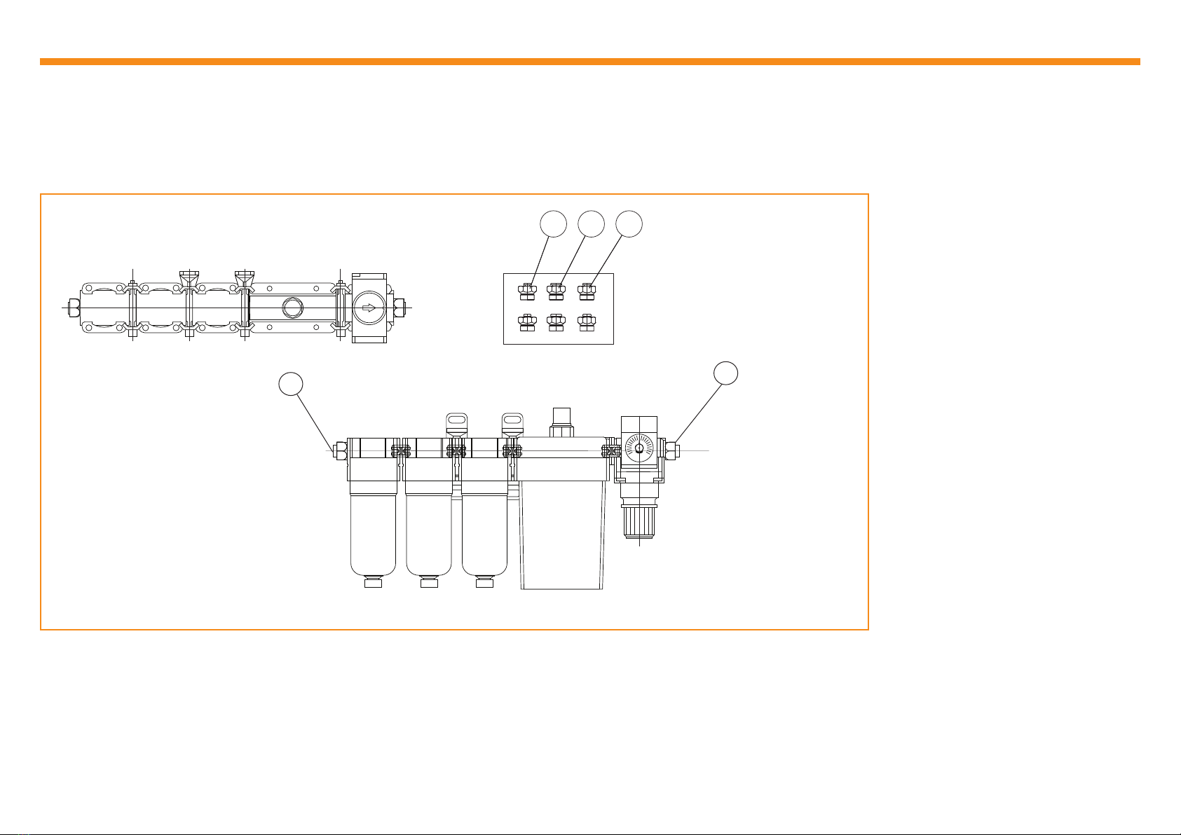
NOTE: The assembly comes complete and in normal
conditions, will not require disassembly.
Check for transit damage and loose components.
Retighten loose components. If components are
damaged, contact your local Renishaw representative.
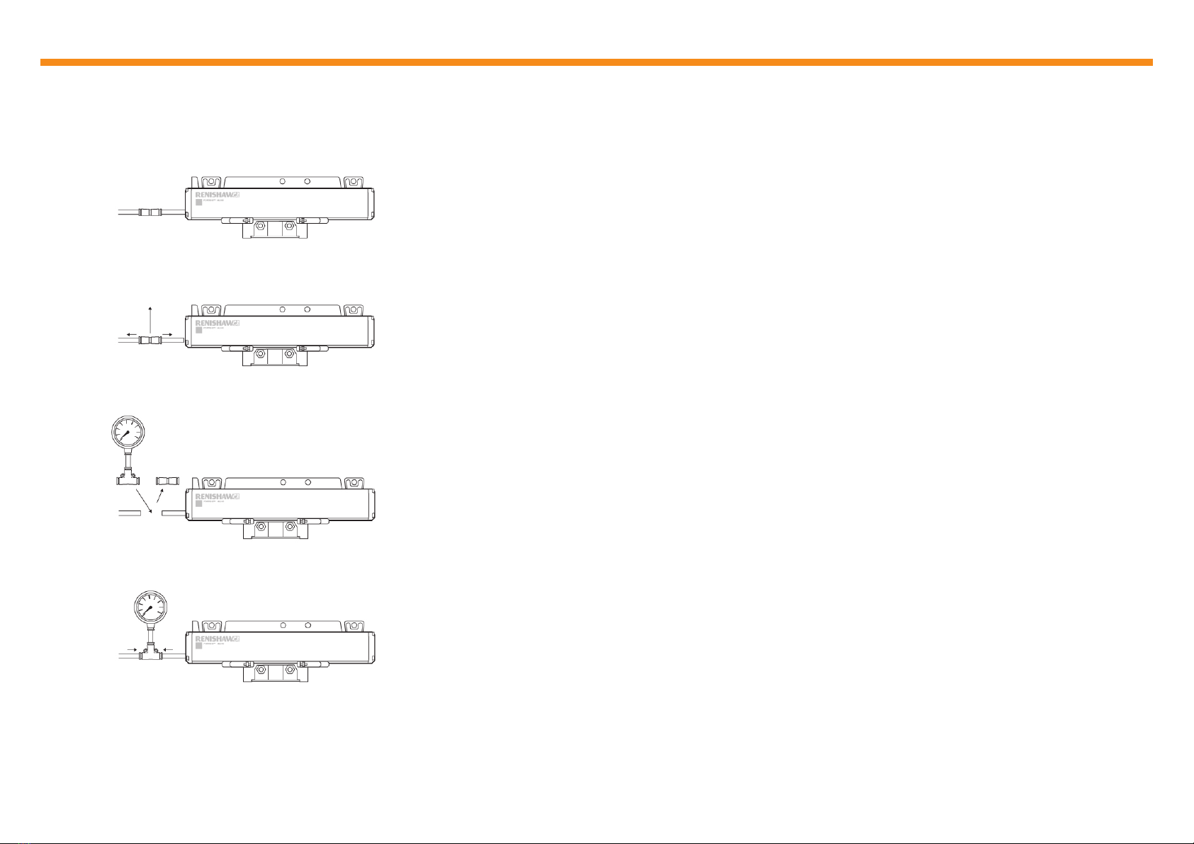
CAUTION: Failure to follow this procedure can cause damage to the pressure regulator knob and the outlet pressure may uctuate.
Pull the pressure regulator knob to unlock. Visually verify that the knob is unlocked using the ‘orange mark’ that appears in the gap.
Rotate the pressure regulator knob clockwise to increase output pressure. Visually verify this on the attached gauge.
To reduce the output pressure, rotate the knob fully anticlockwise until the gauge reduces to zero, then increase pressure until the required level is reached.
Push the pressure regulator knob to lock. If the knob is not easily locked, turn it left and right a little and then push it. Visually verify that the knob is locked;
the ‘orange mark’ in the gap will disappear.
NOTE: The output pressure must always be less than the input pressure. If the output pressure is unattainable, check the site input pressure.
The actual pressure at the encoder may differ from the pressure set at the regulator; pressure may drop within the pipework due to distance. If the pressure
at the encoder is too low, a higher set output pressure may be required at the regulator. This also applies for air supply systems for multiple encoders, as
more usage points can reduce overall pressure.
Installation and set-up (continued)
7 bar (0.7 MPa)
(min. 4 bar / max. 10 bar)
12
12
Orange
mark
Increase
output
pressure
Decrease
output
pressure
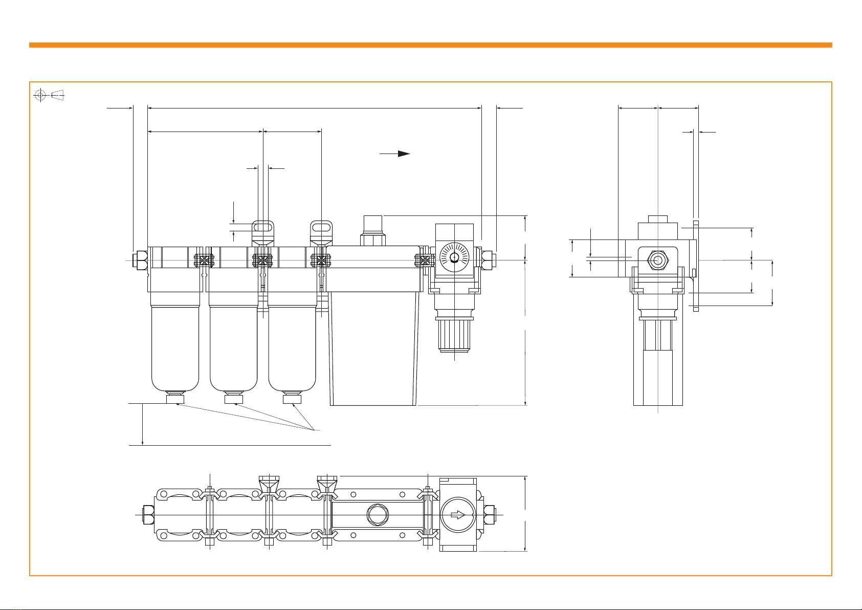
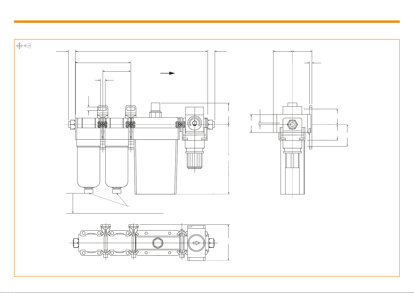
Dimensions and tolerances in mm