REP AMB-BKT-1 User manual

Instructions: AMB-BKT-1©
www.repDesign.us
Page 1 of 4
Version: 20110203
REP Design LLC
INSTALLATION INSTRUCTIONS:
AMB-BKT-1©Standard Heavy Duty "L" Antenna Bracket, Five Optional Antenna Bases
Thank you for your purchase; we appreciate your business and interest in our products.
These instructions describe how to install the AMB-BKT-1©(“BKT”) "L" bracket for mobile HF/V/UHF antennas, for
mobile, fixed-base, temporary/QRP or EMCOMM purposes. It can support essentially any V/UHF mobile antenna and
smaller HF antennas up to small screwdriver or motorized types. The BKT now comes without any antenna base for “your
base”that will fit a ¾ hole or our five (5) interchangeable bases shown below. Our newest base fits the Buddiople TM
Versatee for their dipole HF antennas, even with long radials.
Specifications
6061 aluminum "L" bracket, 1/4 inch thick x 4 x 4 x 2 inches wide.
18-8 stainless steel hardware: 3/8x16, 1.5 inch long, mounting bolts, 1/4x20 ground point with wing nut.
Mounting hole for antenna bases: 3/4 inch diameter, panel thickness ¼ inch.
The BKT now comes without a base, to fit your own, and can be ordered with five of our bases.
Optional bases: interchangeable, include nicely machined rust proof nuts, made of aluminum and stainless steel
components (where applicable) –all compatible ones shown below.
The following photos show the BKT in buffed aluminum (five powder coat finishes also available) with our five optional
antenna bases that fit the BKT. Other photos are included on pages 2-4.
AMB-Bkt-1 bracket, included ¾”hole
& ground point wing nut.
Optional NMO, SO239, 3/8x24 bases
Optional NMO radial base,
four removable SS radials
(135-512 MHz)
Optional “VersaBase”
for BuddipleTM
(Versatee not incl.)
Applications
The BKT can be used by itself or with the our mounts listed below.
CLAMP-200: clamp-on bracket for ladders and railings
BKT-NissanTrac-1 & 2: slide-on bracket for Nissan trucks with "utility track"
Options
AMB-Arm2: 2nd antenna arm, NMO antenna base with four ground plane radials (135-512 MHz) –see below.
AMB-GND-1 & 8: ground counterpoise "rings" for up to eight (8) telescoping or “tuned”(e.g. “hamstick”&
“wonderlead”antennas) whips with a 3/8x24 threaded base, to form a horizontal counterpoise for HF bands. See
photo below. (See special mounting note in Step 2-a).
Version Update: We’ve added our “VersaBase”(for BuddipoleTM antennas) and “NMO radial base”(135-512 MHz) as
additional bases that will fit the BKT. The latest version of these instructions with color photos can be found on our
DOWNLOADS web page, as PDF files.

Instructions: AMB-BKT-1©
www.repDesign.us
Page 2 of 4
Version: 20110203
Safety First!
Use caution if you are installing your antenna on a ladder, balcony or other location where the antenna could fall on
someone or cause damage if it were to fall. If so, you might want to install a “safety line”in case your antenna/mount
comes loose. As with any antenna installation, be careful around thunderstorms and lightening, and you may want to
remove your antenna or disconnect the coax BEFORE a storm appears - remember that if you can hear thunder you
can be struck by lightening! These instructions are meant to provide general guidelines but can not provide all of the
details on how to safely install your mount and antenna, as each installation is unique. If you feel that you cannot safely
install your antenna on the BKT, or it does not meet your needs, you may return it for a refund within two weeks (see
Warranty for details). SAFETY FIRST!
Tools Needed to Install BKT and Options
No special tools are required. A wrench is needed to tighten the mounting bolts and antenna bases.
Installation Suggestions
1) The BKT bolts to your mounting surface (or our other products) using the two provided 3/8 inch bolts. Place flat
washers on either side of the BKT and a lock washer under each nut. You can use longer bolts or wood screws, etc. that
you provide in place of the bolts that we provide, if your application requires a different bolt or screw.
2) Options Installation (SKIP if none used): Install the optional AMB-GND-1 /8 or AMB-Arm2 (if used).
a) The AMB-GND-1/8 counterpoise rings mount into the upper of the two 3/8 holes. Model “1”has four couplers
and Model “8”has eight couplers. They are designed ONLY for fixed base but NOT for mobile use while moving.
The photo below shows the AMB-Gnd-1 installed on the BKT. The AMB-Gnd-8 installs the same way.
SPECIAL MOUNTING NOTE: If you need both bolts to mount the BKT then use the upper bolt to hold the
“ring”–in this case one of the couplers and bolts with the “ring”cannot be used. However, if your mounting
surface is thin you may be able to use one bolt and coupler that came with the “ring”as the upper bolt to
support the BKT, therefore all of the couplers can be used. Alternatively, if you can mount the BKT with only
the BOTTOM bolt, then you can likely use all couplers and whips with the “ring”.
b) The AMB-Arm2 second antenna bracket mounts to the 1/4 inch ground bolt on the BKT. It is designed ONLY for
fixed base but is NOT designed for mobile use while moving. The photo below shows what you get. The bracket
is 13 inches long with a ¼ inch hole for mounting.
3) Attach the antenna base of your choice; your antenna screws onto the base. You can use more than one base as they are
easily interchangeable if you have antennas with different types of bases.
a) The 3/8x24 stud base has an insulating washer with a small lip - the lip is placed into the 3/4 inch hole on top of
the BKT. The 3/8x24 stud coupler rests against this washer so the antenna does not short to ground. The large lock
washer can be placed between the insulating washer and the coupler if desired. The bottom SO239 connector
contacts the BKT for the ground connection.
b) The NMO and SO239 bases have two large stainless steel washers and heavy-duty nut(s) so that they will fit any
hole from 5/8 to 3/4 inches in diameter.

Instructions: AMB-BKT-1©
www.repDesign.us
Page 3 of 4
Version: 20110203
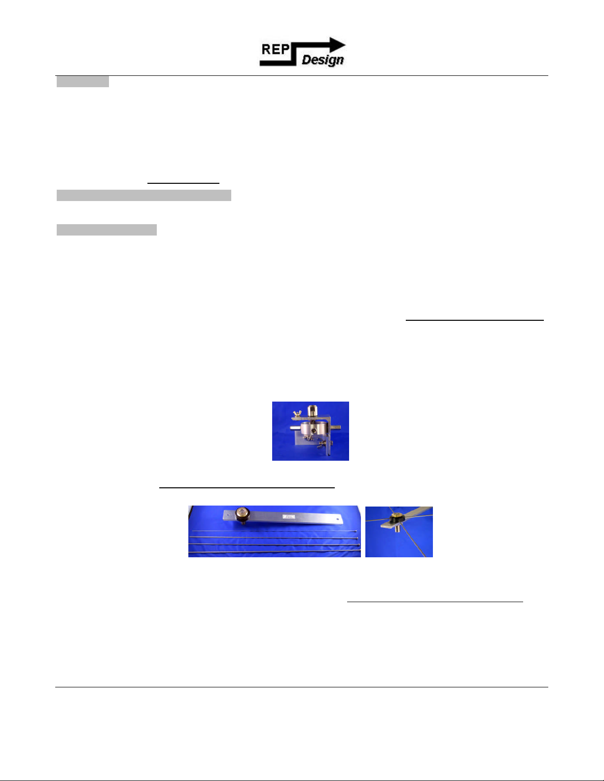
c) The NMO radial base has the same features as the other NMO base (see 3-b) plus it has four removable stainless
steel groundplane radials that are installed with the provided Allen wrench. Note that the hole to mount the NMO
radial base is drilled offset from the center, so you can access the Allen screws without having to remove the base
–simply loosen the base to rotate the base to install or remove each radial.
d) The “VersaBase”attaches to the BKT with the 3/8 inch stainless steel hardware and wing nut, for quick
installation and removal. It will fit the BuddipoleTM Versabase for their dipole HF antennas (Versatee not
included). It is designed for fixed base but NOT for mobile use while driving.
4) Connecting a Ground Counterpoise.
a) For HF, you can use a simple wire counterpoise connected to the provided heavy-duty solder lug on the ¼ inch
bolt with wing nut (use 14 gauge or smaller, even small gauge flat cable works). Use at least four or more wires
that can be cut to the band or simply use at least four 10 foot long radials which can work on 20m and above. Use
longer radials for the lower bands. Our optional AMB-BKT-1/8 counterpoise rings can fit up to four or eight
3/8x24 stud telescoping whips to form a horizontal counterpoise; whips are available (and will work) up to 12 feet
long. The counterpoise, whichever you use, will work best if elevated ABOVE GROUND and not laid on the
ground unless you can install MANY radials. A counterpoise even 5 or more feet above the ground works fine, but
the higher the better. The counterpoise should be somewhat horizontal but can slope away from the antenna. A
counterpoise that is mostly vertical may not work well.
b) For V/UHF (6m and above), the counterpoise (groundplane radials) are connected to the ground point bolt near the
antenna base and works best if slightly shorter than a 1/4 wavelength. For single band antennas, the length should
be "cut" for the band; for multi band antennas cut the radials for the lowest band. These can be made from stiff
wire or whip antennas or other radials sticking out from the base of the antenna. Four are recommended, and can
be approximately horizontal or sloping away from the antenna up to a 45 degree angle. Our "NMO radial base”
does NOT require any additional radials for 2m-70cm and can be used as-is or cut for your specific band, from
135-512 MHz.
5) Antenna and coax suggestions.
Coax connection. Generally, RG-58 size coax works fine for portable or fixed-base installations where the length
of the coax is typically less than 25 feet, especially if you run under 500 watts. You can use any coax you desire.
SWR adjusting device (if needed) for HF antennas, especially those mounted near the ground, to reduce the SWR
to an acceptable level at the antenna resonance point on 160m and 80m, and maybe also on 40m. You may need a
shunt load inductor, UNUN, or additional capacitance to reduce the SWR. Some of these devices need to be
installed at the antenna and if so should be weather resistant (like our SHUNT-100).
Ferrite bead filters to reduce HF antenna tuning problems and to help prevent RFI in devices connected to your
radio. For the HF bands, use Mix 31 or other types that are designed to filter the entire HF band. Do NOT use
unknown ferrites as they may not work at HF frequencies! You may want to install at least 3 ferrites, closely
spaced, over your coax / antenna motor cable as close to your antenna as possible. One of these should have the
coax wound 2-3 times around one of the ferrites (improves filtering at the lower frequencies). Also install ferrites
in a similar fashion on your motor/turns counter cable, and install one ferrite on the coax near your transceiver.
Some installations may require 10 or more ferrites on EACH cable, at the antenna end of the cables. A white paper
on this topic can be downloaded for free from our web page: http://www.repdesign.us/Download.html
Tuning an HF screwdriver / motorized antenna. You can tune your antenna using a DPDT, center off, manual
switch or one of the automatic tuning devices that powers your antenna motor and stops at the resonance point. Do
not confuse these with "antenna tuners", which add capacitance / inductance to match the antenna to the radio -
generally speaking these should NOT be used with "resonant" antennas except to fine tune an SWR that is slightly
too high and can not be reduced by improved grounding, improving the ground counterpoise, installing ferrite
beads or using a load inductor or other device.
Using untuned "whip" antennas. You can use a "CB" whip or longer whip/mast (NOT grounded) which would
only be resonant on one band. To operate other bands you will need some type of antenna tuner.

Instructions: AMB-BKT-1©
www.repDesign.us
Page 4 of 4
Version: 20110203
Spare parts, accessories, downloads and related products.
Let us know if you need spare parts or are looking for something that we do not yet provide –your idea could become a
new product! As a specialty company, we are looking for unique ideas to serve the amateur and two-way radio community.
Warranty Summary
All products include a two (2) week "return for any reason" and six (6) month manufacturing defects limited
warranty. If you should need to return your product please contact us IN ADVANCE to obtain a return
authorization number. Please refer to the complete warranty terms that are enclosed with your order; this is also
included on our web site.
Product Illustrations & Installation Examples
Photos of AMB-BKT-1 with a Hi Q Antennas motorized HF antenna attached to a horizontally mounted CLAMP-200
heavy-duty clamp-on mount. Also shown is an AMB-Gnd-1 counterpoise ring and SHUNT 100.
Photo of AMB-BKT-1 bolted to a BKT-NissanTrac-1 “slide-in”mount for Nissan pickups. Then antenna is a High Sierra
“Sidekick”with “long quick disconnect”.
Thanks for using our products or viewing these instructions on-line. HAPPY DX!
Table of contents