Repotec RPT-1000A User manual

℡
UPS
Emergency Backup Power Supply For Use With Computer Loads Only
Intelligent Auto-Shutdown SoftwarePower Surge/Noise Protection
InternetLineProtection Cost Efficiency
AVR Protection Compact & Reliable Design
U
US
SE
ER
R'
'S
S
M
MA
AN
NU
UA
AL
L
Uninterruptible Power System

IMPORTANT SAFETY INSTRUCTIONS
Thank you for selecting this uninterruptible power system (UPS). It
provides you with better protection for connected equipment.
Please read this manual!
This manual provides safety, installation and operating instructions than will
help you derive the fullest performance and service life that the UPS has to
offer.
Please save this manual!
It includes important instructions for the safe use of this UPS and for
obtaining factory service should the proper operation of the UPS come into
question.
Please save or recycle the packaging materials!
The UPS`s shipping materials were designing with great care to provide
protection from transportation related damage. There materials are
invaluable if you ever have to return the UPS for service. Damage sustained
during transit is not covered under the warranty.

NOTES
- 12 -
CAUTION
¾The UPS contains voltage that are potentially hazardous. All repairs
should be performed by qualified service personal.
¾The UPS has its own internal energy source (battery). The output
receptacles may be alive even when the UPS is not connected to anAC
supply.
¾The UPS is suitable for computers and electronic equipment with
substantially rectifier or capacitive loads, not suitable for electronic
equipment with significant inductive loads, such as motors & fluorescent
lamps.
¾Be sure to operate within the power rating of the UPS. Below 1/2 or 1/3
of rated power is recommended for longer backup time & longer battery
life.
¾Do not place the UPS near excessive humidity, under sunshine, or close
to heat-emitting sources.
¾If the UPS is out of order, please detach power cord and consult your
dealer right away. Do not remove cover if there is no serviceable part
inside.
¾The unit should be supplied by grounded source. Do not operate the
unit without ground source.
¾The socket-outlet should be installed near the equipment and be easily
accessible.
¾Do not plug the UPS power cord into itself. That will result in a safety
hazard.
¾Installation should be performed by a qualified technician or electrician
in accordance with local electrical codes.
- 1 -

SPECIFICATIONS
Capacity VA 800VA 1000VA
Voltage 100VAC, 110VAC, 120VAC, 220VAC, 230VAC or 240VAC
±25%
Input
Frequency 50Hz or 60Hz ±5%
Voltage (Batt. Mode) 100VAC, 110VAC, 120VAC, 220VAC, 230VAC or 240VAC
±10%,
Frequency 50Hz or 60Hz ±1Hz
Waveform Modified sine wave
Output
Transfer Time Less than 4ms (typical)
Battery Type Sealed, maintenance-free lead acid batteries with 3-5
years typical lifetime
Battery
Recharge Time 5 hours to 90% of full capacity
Indicator LED LED indicator for line on, battery back-up, UPS cut-off
Battery Back-up Sounding every 3 seconds
Battery Low Sounding every 1 second
Alarm
Overload Continue beeping sound
Overload Fuse & current limited
Short Circuit Fuse & current limited & cut-off
Protection
Batt. Low Cut-off No battery drain after cut-off
Physical Dimension, D*W*H 385*94*170 mm
Operating Temperature 32℉-104℉at full load, 0~90% relative humidity
(non-condensing)
Environment
Noise Level Less than 40db (at 1 meter)
Contact Closure DB9 connector for connecting with Rups-2000 software
Interface Software Rups-2000 (Option)
- 10 -
SYSTEM CONCEPT
The purpose to present this chapter is to give you more precise conception
about how UPS works..
1. Block Diagram
AVR.
INV.
CHA.
N.F. N.F.
INPUT OUTPUT
Fig. 1 shows how UPS works.
2. Normal Operation
There are two main loops whenAC Utility normal the AC output loop and the
battery charging loop. The AC output gets power from AC utility input and
pass through AVR to support power to load. In the same time, the AC utility
input is converted by AC/DC CHA and support charging power to charge
batteries.
AVR.
INV.
CHA.
N.F. N.F.
INPUT OUTPUT
Fig. 2 shows how the UPS works when AC Utility normal.
- 3 -

COMPUTER INTERFACE
The computer interface (DB9 port) on the back of the UPS may be
connected to a host computer. This port allows the computer to monitor the
status of the UPS and control the operation of the UPS.
Pin out information:
PIN# Description I/O
Output
Input
Input
Output
PIN1
PIN2
PIN3
PIN4
PIN5
PIN6
PIN7
PIN8
PIN9
Battery low, normally open, active close
N.C.
Common Ground
Remote shut down, keep this pin high
(+5~+12V) for 3S will turn off the UPS
N.C.
N.C.
Must keep in high state
Line fail, normally open, active close
N.C.
12345
6789
D-SUB 9 Pin Female Connector
SignalHigh Min. 3 Second
Contacts
Normally
Open
Low Battery
Mains Failure
Pin Number
UPS Shut Down
5
8
6
3
1
4
7
2
9
- 8 -
OVERVIEW
Front Panel
1. Master Power Switch: Turn on/off the UPS.
2. Green LED: AC Normal .
3. Yellow LED: Battery in back-up
4. Red LED: UPS Cut-off
Rear Panel
1. Input: IEC type connector to connect the power cable.
2. AC Fuse: Protection against short-circuits electronic fuse.
3. Data line protection: Filtering of electrical noise on data transmission
lines.
4. Communication port: Basic communications.
5. AC/Battery outputs: Output protected for critical loads that require
additional electrical power
6. UPS function setup: No load auto-shut down, Dc-start On and Buzzer
Alarm auto-reset.
7. USB PORT (OPTION)
Picture:
1
234
- 5 -

CONTENTS
PAGE
1. CAUTION…………………………………………………………..…..1
2. INTRODUCTION
SYSTEM DESCRIPTION………………………….……………..2
FEATURES………………………………….……………………..2
3. SYSTEM CONCEPT
BLOCK DIAGRAM……………………………….………………..3
NORMAL OPERATION………………………….………………..3
AC UTILITY FAILURE………………………….…………………4
4. OVERVIEW
FRONT PANEL……………………………………………………5
REAL PANEL………………………………………………………5
PICTURE…………………………………………………….…….5
5. INSTALLATION AND OPERATION…………………………………7
6. COMPUTER INTERFACE……..…………………………………….8
7. BATTERY FACTS……………………………………………………..9
8. SPECIFICATIONS……………………………………………………10
9. TROUBLE SHOOTING………………………………...……………11
10.NOTES…………………..……………………….………………….12

INTRODUCTION
System Description
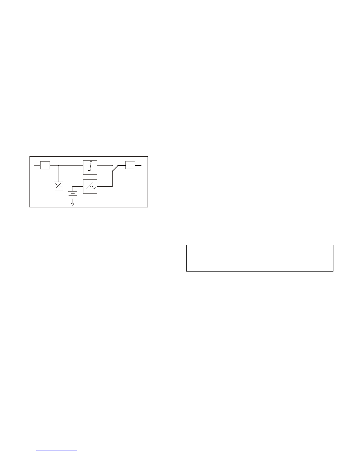
The product is line interactive UPS with the newest technology and powerful
function. The Line Interactive UPS is withAVR function allows input voltage
range from 75% to 125%, including on line voltage boost-up & buck down.
An ideal protection equipment for critical connected loads.
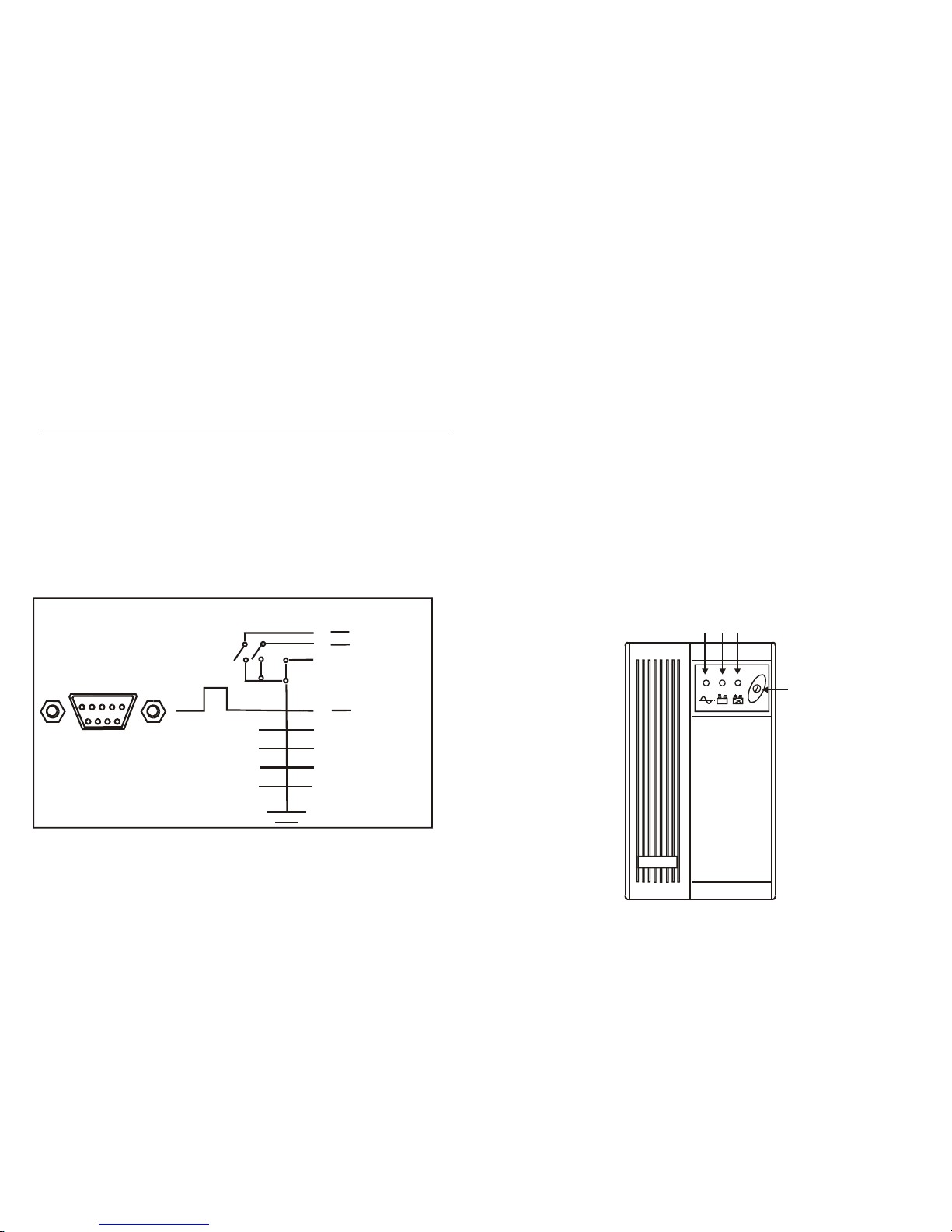
In addition, This UPS provides advanced single telephone line or modem
surge suppression through the modular connectors on the back panel.
The Line Interactive UPS and RUPS2000 monitoring software (Optional kits)
makes our computer operate intelligent and provides you with the ability of
perfect protection of your critical devices.
Features
¾Line interactive design.
¾Easy LED display.
¾Provide boost and buck AVR to stabilize input voltage.
¾Provides lightning, surge, overload, and short-circuit protection.
¾Built-in CCCV battery charger and battery over drain protection.
¾Auto restart whenAC recovery.
¾Cold start function (Dip power on).
¾Tel / Modem / Fax / Internet surge suppression.
¾Option Bundle software:Automatically save your valuable files before
auto shutdown.
- 2 -
TROUBLE SHOOTING
If the UPS failed to operate properly, please review the following checks
firstly. If the problem remain, please consult sales agent for service.
Is the Master power switched on?
Is the UPS plugged into a correctly working outlet?
Is the line voltage within the rating specified?
Is the fuse on the rear panel blown?
Is the UPS over loaded?
Is battery not fully charged? Dead battery? Charger failure?
Please provide the following information when call for service.
1. Model number, serial number.
2. Date of the problem occurred, date of purchase.
3. Full description of the problem including load, LED, and alarm status,
installation condition, working environment, etc.
Trouble-Shooting Chart
Problem Possible Cause Caution To Take
Front panel switch
in off position. Turn on switch.
Rear panel fuse
burnout. Replace fuse restart UPS.
No light, and no alarm
(UPS not on)
Power cord lose Check input power.
No “Green LED "
light, and alarm beeps
every 3 seconds. AC Fuse burnout. Replace fuse, if problem
remains, call for service.
Backup time is less
than the rating.
Battery is not fully
charger failure.
Recharge the battery for at
least 6 hours, re-test the
backup time. If problem
remains, call for service.
- 11 -

3. AC Utility Failure
If AC utility fails, the UPS quickly detects the problem and activates the
inverter. The inverter. The DC/AC inverter changes DC power from the
batteries into AC and provides continuous uninterruptible power to load.
AVR.
INV.
CHA.
N.F. N.F.
INPUT OUTPUT
Fig. 3 shows how the UPS works when AC Utility Failure
- 4 -
BATTERY FACTS
The battery is the only periodically serviceable parts in the UPS. An
expected life is approx. 3∼5 years. However, frequent long discharges or
ambient temperatures above 80°F will shorten battery life. Therefore, it is
recommended to replace the batteries every 3 years after initiating the unit.
Recharge batteries every 3 months is necessary if it is not in use because it
may cause batteries over-drain.
WARNING
Only a qualified technician should replace the battery. Batteries have
high short-circuit current capacity; mistakes in connecting or
disconnecting can cause connections to arc or weld and could cause
severe burns.
STORAGE
The UPS should only be stored if the battery is fully charged. Avoid storage
temperatures above 80°F as battery life is significantly shortened. Every 90
days remove the unit from storage and plug it in for 24 hours to recharge the
batteries. Batteries may be damaged if left in storage and not recharge
every 90 days.
IMPORTANT NOTICE
Please use same type and same rating of batteries for replacement.
Do not replace it with the battery that exceeds specified rating.
- 9 -

Rear Panel:
NEMA5-15R
IEC-320
IN OUT
INTERNET
REMOTE
AC/BATTERY OUTPUTS
AC INPUT
4
5
2
3
1
6
3 2 1
IN OUT
INTERNET
REMOTE
AC/BATTERY OUTPUTS
AC INPUT
46
5
2
3
1
3 2 1
IN
OUT
INTERNET
REMOTE
A
C/BATTERY OUTPUTS
ACINPUT
4
5
2
3
1
6
3 2 1
6
IN
OUT
INTERNET
REMOTE
AC/BATTERY OUTPUTS
ACINPUT
4
5
2
3
1
3 2 1
77
77
- 6 -
INSTALLATION AND OPERATION
Upon receipt of the UPS, inspect the shipping carton for damage. If there is
any obvious damage, immediately report it to the selling dealer or the
delivering carrier. If there is no damage to the shipping carton, unpack the
unit and inspect the unit for damage.
The UPS is designed for installation in a protected environment within a
temperature range from 32°F to 104°F and relative humidity of 0∼90%
without condensation. Do not block inlets and outlets. Install the system in a
location free from excessive dust and chemical fumes.
Check the identification label to verify the UPS voltage and power rating
match the available line voltage and load requirements.
Installation:
1. Check if the main switch on the UPS front panel is in the off position and
insure that the voltage of the AC utility source corresponds to the
nameplate on the UPS rear panel.
2. Connect the power cord to a verified grounded 3-wire receptacle.
3. Turn on the power switch of UPS, the green LED will be lit indicating AC
utility voltage is present.
4. Charge the batteries for ten (10) hours before use. You may use the
UPS immediately without recharging, but the backup time maybe less
than the rating.
5. Connect your computer to the output receptacles of the UPS.
6. To test backup function, you may disconnect the power cord of the UPS
from wall outlet. The Yellow LED will light on, and alarm will beep every
3 seconds.
7. When battery approaches low level, alarm will beep every second until
auto shut down.
8. The 4 conditions UPS will automatically shut down:
a. Battery low
b. Short circuit
c. Overload
d. UPS fault
- 7 -


Table of contents
Other Repotec UPS manuals