resideo Protectorelay User manual

INSTALLATION INSTRUCTIONS
69-0618-04
R4184D; R8184G,M,N,P
Protectorelay® Oil Primary Controls
APPLICATION
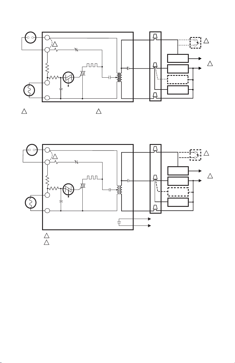
The intermittent ignition R4184D and R8184G,M,N,P Oil
Primary Controls operate the oil burner, oil valve (if
desired) and the ignition transformer in response to a
call for heat from the thermostat.
The R8184M also provides automatic, nonrecycling
control of cooling systems and low voltage thermostat.
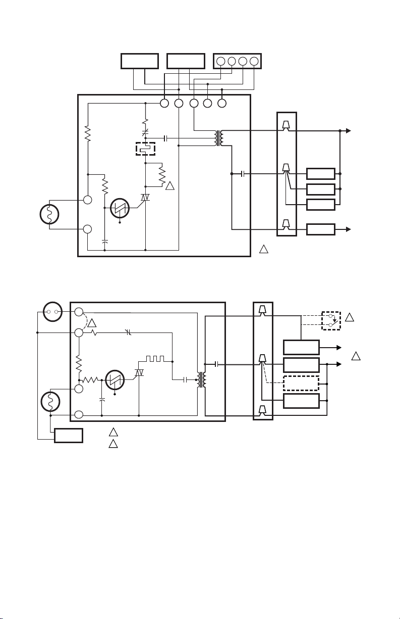
The R8184P provides 15-second valve on delay and
selectable 0-, 2-, 4-, 6-minute blower off delay for
hydronic and warm air systems. Select models have 30-
minute blower off delay timing.
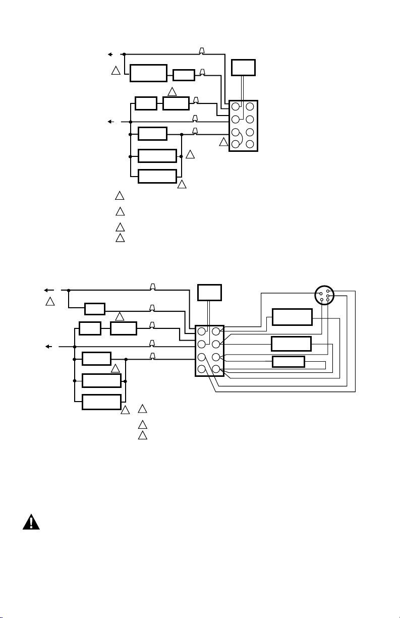
All models use the C554A Cadmium Sulfide (cad cell)
Flame Detector to monitor the burner flame and shut
down the system on ignition failure or on flame failure
during the run cycle. A manual reset button is provided
to reset the safety switch after lockout. Clock
thermostats (not available on R8184P) that power the
clock through the primary control transformer lose time
during lockout unless backup batteries are installed.
All models (except the R8184G1310 and R8184G1328)
are Underwriters Laboratories Inc. component
recognized and meet flammability test requirements for
a final enclosure.
NOTE: R8184P is intended for use on oil burning appli-
ances that do not require a safety rated pre-
purge and postpurge function as defined in UL
296. The valve on delay and blower off delay in
this control are only intended to help establish
draft and reduce oil after drip-related problems.
INSTALLATION
When Installing This Product…
1. Read these instructions carefully. Failure to follow
them could damage the product or cause a haz-
ardous condition.
2. Check the ratings given in these instructions to
make sure the integrated furnace control is suit-
able for your application.
3. Installer must be a trained, experienced service
technician.
4. After completing the installation, use these
instructions to check out the product operation.
CAUTION
1. Disconnect the power supply before beginning
installation to prevent electrical shock or
equipment damage.
2. Be sure the combustion chamber is free of oil
or oil vapor before starting the system.
Location
1. Mount on a 4 x 4 junction box, directly on the main
burner housing or inside the appliance cabinet.
See Fig. 1.
2. Be sure that operating temperatures are between
-40°F and +130°F (-40°C and +54°C). Select
R8184G,P models have a maximum temperature
of 150°F (66°C), but must be mounted parallel to
the ground to achieve 150°F (66°C). See Fig. 2.
Fig. 1. Wire and mount 130°F (54°C) maximum ambient
temperature oil primary control.
CAD
CELL LEADS
LINE
VOLTAGE LEADS MOUNTING
SCREW HOLE
RED RESET
BUTTON
4 x 4 JUNCTION
BOX
HOLE OR KNOCKOUT FOR
CAD CELL LEADS
LOW VOLTAGE
TERMINAL STRIP
1STRIP WIRES 3/8 in. (9.5 mm); INSERT FROM SIDE, ABOVE OR BELOW.
T-T TERMINALS ON R8184G; T1-T2 TERMINALS ON R8184N.
1
2
2
M1643D

R4184D; R8184G,M,N,P PROTECTORELAY® OIL PRIMARY CONTROLS
69-0618—04 2
Fig. 2. Wire and mount 150°F (66°C) maximum ambient
temperature oil primary control.
Line Voltage Wiring Connections
Wiring must comply with all local codes and ordinances.
1. Be sure all line voltage connections are in a wiring
enclosure such as a junction box or the appliance
wiring compartment.
2. Make the line voltage connections as shown in
Fig. 3 through 9.
3. Splice the leads with solderless connectors.
IMPORTANT
Do not exceed the load ratings listed in Table 1.
4. Thread the line voltage cad cell leads through the
hole on the bottom of the low voltage terminal
strip. See Fig. 1 or 2.
Alarm Contact Rating: 25 VA at 24V, 50/60 Hz.
Mounting
1. If necessary, use the control as a template to mark
and drill new mounting holes.
2. Mount the control using no. 8 screws (obtained
locally).
Low Voltage Wiring Connections
After mounting, make low voltage connections to screw
terminals as follows:
• R4184D—connect the cad cell leads to the F-F
terminals. See Fig. 3.
• R8184G—connect the cad cell leads to the F-F
terminals and thermostat leads to the T-T terminals.
See Fig. 4 and 5.
• R8184M—connect the cad cell leads to the F-F
terminals and connect remaining low voltage wiring
as shown in Fig. 6.
NOTE: The Y and G terminals are not connected to the
internal circuitry of the R8184M. The Y and G
terminals are provided to simplify the connec-
tions of the cooling equipment.
• R8184N—connect the cad cell leads to the F1-F2
terminals and thermostat leads to the T1-T2
terminals. See Fig. 7.
• R8184P hydronic hookup. Connect the cad cell leads
to the F-F terminals. See Fig. 6.
• R8184P warm air hookup. Connect the card cell leads
to the F-F terminals and the thermostat leads to the
R-W terminals. See Fig. 9.
Fig. 3. Typical hookup for R4184D.
CAD
CELL LEADS
LINE
VOLTAGE LEADS MOUNTING
SCREW HOLE
RED RESET
BUTTON
VENTILATION
SLOTS
4 x 4 JUNCTION
BOX
HOLE OR KNOCKOUT FOR
CAD CELL LEADS
LOW VOLTAGE
TERMINAL STRIP
1STRIP WIRES 3/8 in. (9.5 mm); INSERT FROM SIDE, ABOVE OR BELOW.
ATTACH WITH NO. 8 MOUNTING SCREWS (OBTAINED LOCALLY).
VENTILATION SLOTS ONLY AVAILABLE ON SELECT MODELS.
1
2
2
3
3
M1642C
Table 1. Load relay contact ratings.
Model
120 Vac 240 Vac
AFL ALR AFL ALR
R4184D; R8184G,M,N
(45-second models)
7.4A 44.4A 3.7A 22.2A
R8184P (15-, 30-, 45-
second models)
7.4A 44.4A NA NA
R8184G (15- and
30-second models)
10.0A 60.6A 5.0A 30.0A
JUNCTION BOX
BLACK
ORANGE
WHITE
R2
SAFETY
SWITCH
M715A
POWER SUPPLY. PROVIDE DISCONNECT MEANS
AND OVERLOAD PROTECTION AS REQUIRED.
CAD
CELL F
F
R4184D PROTECTORELAY CONTROL
SAFETY
SWITCH
HEATER
1K
TRIAC
BILATERAL
SWITCH
CAPACITOR
R1
1K2
1K1
1
1
IGNITION
LIMIT
THERMOSTAT
OIL VALVE
(OPTIONAL)
BURNER
MOTOR
L2
L1
(HOT)
®

R4184D; R8184G,M,N,P PROTECTORELAY® OIL PRIMARY CONTROLS
369-0618—04
Fig. 4. Typical hookup for R8184G.
Fig. 5. Typical hookup for R8184G with dry contacts for remote alarm.
JUNCTION BOXTHERMOSTAT
BLACK
ORANGE
WHITE
R2
SAFETY
SWITCH
M716A
POWER SUPPLY. PROVIDE DISCONNECT MEANS
AND OVERLOAD PROTECTION AS REQUIRED.
CAD CELL F
T
T
F
R8184G PROTECTORELAY® CONTROL
SAFETY
SWITCH
HEATER
1K
TRIAC
BILATERAL
SWITCH
CAPACITOR
R1
1K2
1K1
1TO USE R8184 WITH LINE VOLTAGE CONTROLLER, JUMPER T-T TERMINALS AND
CONNECT LINE VOLTAGE THERMOSTAT IN SERIES WITH LIMIT CONTROLLER.
2
2
2
1
IGNITION
LIMIT
LINE VOLTAGE
THERMOSTAT
OIL VALVE
(OPTIONAL)
BURNER
MOTOR L2
L1
(HOT)
JUNCTION BOXTHERMOSTAT
BLACK
ORANGE
WHITE
RED
RED
R2
SAFETY
SWITCH
SAFETY
SWITCH
TO REMOTE
ALARM CIRCUIT
M5172A
POWER SUPPLY. PROVIDE DISCONNECT MEANS AND OVERLOAD PROTECTION AS REQUIRED.
TO USE R8184 WITH LINE VOLTAGE CONTROLLER, JUMPER T-T TERMINALS AND CONNECT LINE VOLTAGE THERMOSTAT
IN SERIES WITH LIMIT CONTROLLER.
CAD CELL F
T
T
F
R8184G PROTECTORELAY® CONTROL
SAFETY
SWITCH
HEATER
1K
TRIAC
BILATERAL
SWITCH
CAPACITOR
R1
1K2
1K1
1
2
2
2
1
IGNITION
LIMIT
LINE VOLTAGE
THERMOSTAT
OIL VALVE
(OPTIONAL)
BURNER
MOTOR
L2
L1
(HOT)

R4184D; R8184G,M,N,P PROTECTORELAY® OIL PRIMARY CONTROLS
69-0618—04 4
Fig. 6. Typical hookup for R8184M.
Fig. 7. Typical hookup for R8184N.
M1560B
USED FOR 4 AMP THERMOSTAT ONLY.
CAD
CELL
F
RWY
THERMOSTAT
G
FAN RELAY
COOLING
CONTACTOR
WCRY
F
G
(T)(T)
R8184M
PROTECTORELAY®
CONTROL
K1
SS
SAFETY
SWITCH
HEATER
R4
1K1 BLUE
RED
BROWN
TRIAC
BILATERAL
SWITCH
CAPACITOR
R2
R1
1K2
BLACK
WHITE
ORANGE
BLACK
JUNCTION
BOX
IGNITION
OIL VALVE
BURNER
LIMIT L1
(HOT)
L2
1
1
JUNCTION BOXTHERMOSTAT
BLACK
ORANGE
WHITE
R2
SAFETY
SWITCH
M717A
POWER SUPPLY. PROVIDE DISCONNECT MEANS AND OVERLOAD PROTECTION AS REQUIRED.
TO USE R8184N WITH LINE VOLTAGE CONTROLLER, JUMPER T1-T2 TERMINALS AND CONNECT
LINE VOLTAGE THERMOSTAT IN SERIES WITH LIMIT CONTROLLER.
CAD CELL F1
T1
T2
F2
R8184N PROTECTORELAY CONTROL
SAFETY
SWITCH
HEATER
1K
TRIAC
BILATERAL
SWITCH
CAPACITOR
R1
1K2
1K1
1
2
2
2
1
IGNITION
LIMIT
LINE VOLTAGE
THERMOSTAT
OIL VALVE
(OPTIONAL)
BURNER
MOTOR
.4064T
HEATER
L2
L1
(HOT)
®

R4184D; R8184G,M,N,P PROTECTORELAY® OIL PRIMARY CONTROLS
569-0618—04
Fig. 8. Typical hydronic hookup for R8184P.
Fig. 9. Typical warm air hookup for R8184P.
CHECKOUT
Start System
WARNING
FIRE OR EXPLOSION HAZARD
CAN CAUSE PROPERTY DAMAGE, SEVERE
INJURY OR DEATH
Be sure the combustion chamber is free of oil or
oil vapor before starting the system.
1. Push in and release the red reset button.
2. Open the hand valve in the oil supply line.
3. Make sure the system is powered. Check the circuit
breaker or fuse and close the system switch, if pro-
vided.
NOTE: If the safety switch has just locked out,
the safety switch may need a minute to
cool down before it can be reset.
4. Set thermostat to call for heat.
5. Burner should light and operate until a call for heat
ends.
1 POWER SUPPLY. PROVIDE DISCONNECT MEANS AND
OVERLOAD PROTECTION AS REQUIRED.
2 IGNITION TRANSFORMER CAN BE CONNECTED TO VALVE OR
BURNER MOTOR.
3 OMIT ON SYSTEMS WITHOUT POWER VENTING.
4 JUMPER R-W.
RED
BLACK
VIOLET
WHITE
ORANGE
L1
(HOT)
F
L2
(LINE)
1
3
2
3
M10022
OIL
VALVE
AIR FLOW
SWITCH
AQUASTAT®
CONTROLLER
BURNER
MOTOR
IGNITION
TRANSFORMER
VENTER
MOTOR
CAD
CELL
F
R
W
RC
Y
G
C
R8184P
PROTECTORELAY®
HYDRONIC
CONTROL
4
LIMIT
THERMOSTAT
M10021
1 POWER SUPPLY. PROVIDE DISCONNECT MEANS AND
OVERLOAD PROTECTION AS REQUIRED.
2 IGNITION TRANSFORMER CAN BE CONNECTED TO VALVE OR BURNER MOTOR.
3 OMIT ON SYSTEMS WITHOUT POWER VENTING.
RED
ORANGE
BLACK
VIOLET
WHITE
L1
(HOT)
F
L2
(LINE)
1
3
2
3
LIMIT
OIL
VALVE
AIR FLOW
SWITCH
COOLING
TRANSFORMER
COOLING
CONTACTOR
FAN RELAY
BURNER
MOTOR
IGNITION
TRANSFORMER
VENTER
MOTOR
CAD
CELL
F
R
W
RC
Y
G
C
R8184P
PROTECTORELAY®
WARM AIR
CONTROL
NOTE: USE COPPER CONDUCTORS ONLY

R4184D; R8184G,M,N,P PROTECTORELAY® OIL PRIMARY CONTROLS
69-0618—04 6
Check Safety Features
Simulate flame failure:
1. Follow the starting procedure to turn on the burner.
2. Close the hand valve in the oil supply line.
3. Safety switch should lock out in safety switch tim-
ing indicated on the label (15, 30 or 45 seconds).
Alarm switch contacts close to initiate alarm on
models with remote dry contacts. Ignition and
motor should stop and oil valve should close.
4. Push red reset button to reset safety switch.
Simulate ignition failure:
1. Follow the starting procedure to turn on the burner,
but do not open the oil supply hand valve.
2. Safety switch should lock out in safety switch tim-
ing indicated on the label. Alarm switch contacts
close to initiate alarm on models with remote dry
contacts. Ignition and motor should stop and oil
valve should close.
3. Push the red reset button to reset the safety
switch.
Simulate power failure:
1. Follow the starting procedure to turn on the burner.
2. With the burner running, turn off the power to the
system by tripping the circuit breaker or removing
the fuse.
3. Burner should stop.
4. Restore power. Burner should start.
If system does not operate as described, go to the
“Troubleshooting and Maintenance” on page 6.
TROUBLESHOOTING AND
MAINTENANCE
IMPORTANT
1. Only a trained, experienced service technician
should perform the troubleshooting procedure.
2. This control contains no field-replaceable parts.
Do not attempt to take it apart. Replace the
entire control if operation is not as described.
Preliminary Steps
1. Check the wiring connections and power supply.
Make sure power is on to the controls, burner
motor and ignition transformer.
2. Make sure the limit control is closed.
Check Oil Primary Relay
NOTE: You will need an insulated jumper wire with both
ends stripped.
1. Disconnect cad cell leads from F-F or F1-F2termi-
nals.
2. Reset the safety switch and set the thermostat to
call for heat. Burner should start.
3. Within the safety switch timing, use insulated wire
to jumper F-F or F1-F2terminals. Burner should
continue to run.
4. After the safety switch timing, remove the jumper.
Burner should shut down in the safety switch tim-
ing.
5. If the operation is not as described, replace the oil
primary control.
Check Cad Cell
1. Disconnect the power at the system switch, circuit
breaker, or fuse.
2. Disconnect cad cell leads from F-F or F1-F2termi-
nals.
3. Clean the cell face with a soft cloth.
4. Make sure the cell is seated securely in the socket.
Be careful not to disturb the socket position.
5. Reconnect the cad cell leads to F-F or F1-F2termi-
nals.
6. Reset the safety switch, turn on the power and set
the thermostat to call for heat.
7. If burner does not operate or if safety switch trips,
replace the cad cell. Order Resideo part no. 130367
Cad Cell.

R4184D; R8184G,M,N,P PROTECTORELAY® OIL PRIMARY CONTROLS
769-0618—04

R4184D; R8184G,M,N,P PROTECTORELAY® OIL PRIMARY CONTROLS
© 2020 Resideo Technologies, Inc. All rights reserved.
This product is manufactured by Resideo Technologies, Inc. and its affiliates.
www.resideo.com
Resideo Technologies, Inc.
1985 Douglas Drive North, Golden Valley, MN 55422
1-800-468-1502
69-0618—04 M.S. Rev. 06-20 | Printed in United States
This manual suits for next models
5
Table of contents
Other resideo Relay manuals