resideo R8845U User manual

PRODUCT DATA
68-0215-02
R8845U Universal Switching Relay
APPLICATION
The R8845U Universal Switching Relay provides intermediate
switching of line- and low-voltage devices from a line- or
lowvoltage controller. The R8845U may be used to replace
several Resideo or competitive switching relays and is
typically applied in hydronic heating systems.
FEATURES
• Replaceable, socketed relays.
• Replacement relay common to other hydronic replacement
controls.
• Two troubleshooting LEDs.
• Push-to-test button.
• Replaceable transformer fuse.
• Low-voltage contact ratings for Powerpile® applications.
• Long-life DC relay drive control technology.
• Relays can be used with external 24 Vac or 24 Vdc supply,
line-voltage control, or with internal 24V transformer.
• One model replaces several competitor models.
• One model replaces many Resideo models: R182A,B,C,J;
R482A,B,C,J; R845A, R882A,B,C,J and RA832A. (See
Table 1, Replacement Cross Reference.)
SPECIFICATIONS
IMPORTANT
The specifications given in this publication do not
include normal manufacturing tolerances. There-
fore, this unit may not exactly match the listed spec-
ifications. Also, this product is tested and calibrated
under closely controlled conditions, and some minor
differences in performance can be expected if those
conditions are changed.
Model: R8845U Universal Switching Relay with 24V control-
ler for switching one- or two-line voltage loads and one
low-voltage load.
Electrical Ratings:
Voltage: 120 Vac, 60 Hz.
Thermostat Heat Anticipator Setting: 0.12A.
Transformer Ratings:
Primary: 120V, 60 Hz.
Secondary: 24 Vac, 12 VA maximum, 9 VA available for exter-
nal loads. Secondary protected by replaceable 1A auto-
motive fuse.
Contact Ratings: 7.4 AFL, 44.4 ALR on each set of line-volt-
age contacts; maximum connected load is 2000 VA.
Switching Action: Two Spst, plus Powerpile® rated low-volt-
age Spst. If normally closed contacts are needed, use
RA889A.
Temperature Ratings:
Ambient: -20°F to 120°F (-29°C to 49°C).
Humidity Ratings: 0 to 90% rh, non-condensing.
Electrical Connections: No. 8 captivated wire clamp screw
terminals.
Finish: Zinc plated steel.
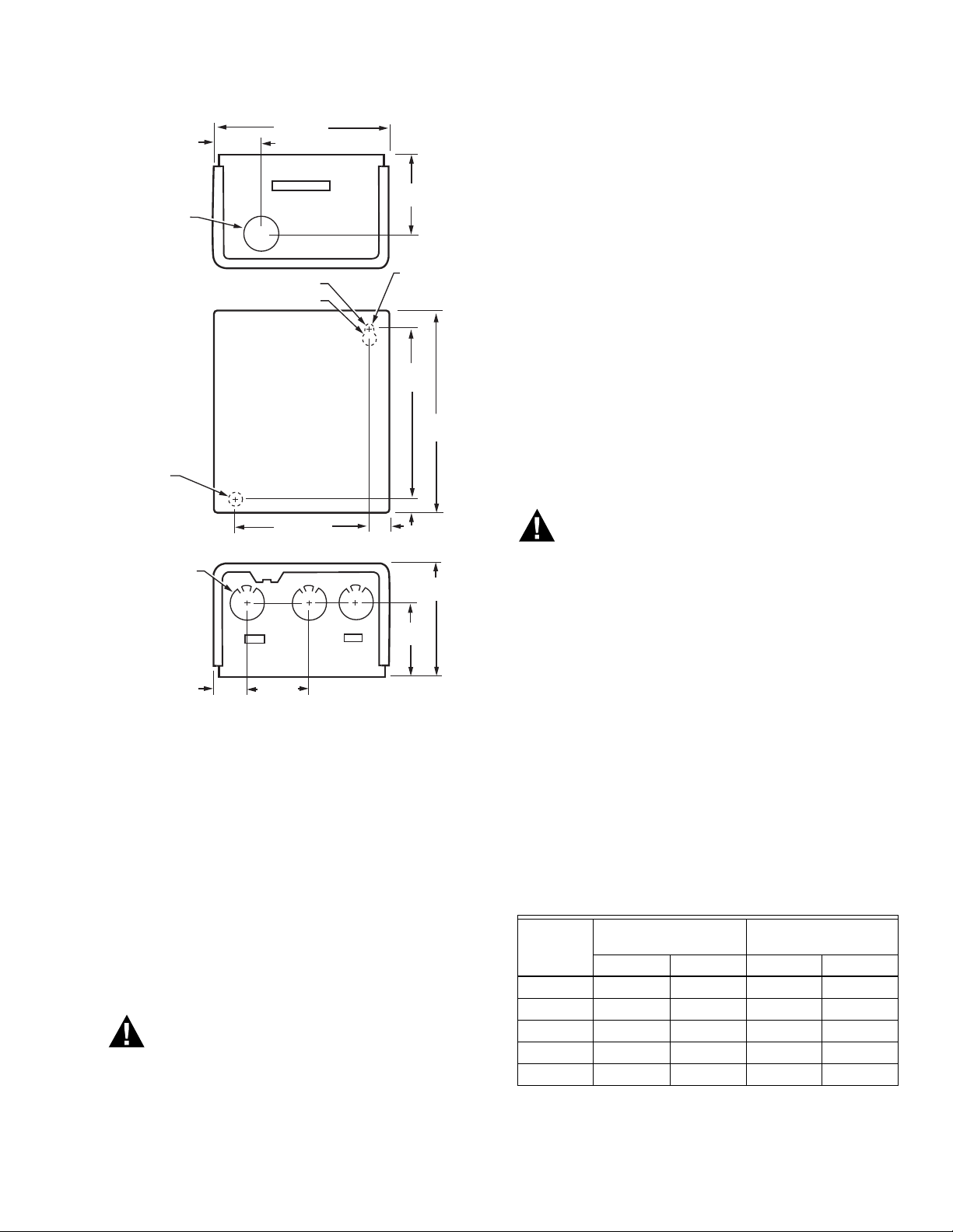
Knockouts:
Case Bottom: Three 1/2 in. (13 mm) for conduit box.
Case Top: One 7/8 in. (22 mm) for wiring.
Approvals:
Underwriters Laboratories Inc. Listed: File no. E4436, Guide
no. XAPX.
Canadian Underwriters Laboratories Listed: Guide no.
XAPX7.

R8845U UNIVERSAL SWITCHING RELAY
68-0215—02 2
Dimensions: See Fig. 1.
Cross Reference: The R8845U replaces Resideo models
R182A,B,C,J; R482A,B,C,J; R845A, R882A,B,C,J and
RA832A, as well as several competitive models. See Table
1 for additional cross reference information.
Thermostat Compatibility: All Resideo electromechanical
and most electronic 2- or 3-wire. Select thermostats with
0.12A heating anticipator settings to match the electrical
rating of the R8845A Switching Relay.
Replacement Parts:
32002190-001 Replacement Relay.
Replacement Fuse: Use a 1A automotive fuse.
Table 1. R8845U Replacement Cross Reference.
Manufacturer Model
Connections
Comments
InputLine
Voltage
Power
Relay 1
Power
Relay 2
Line
Voltage
Relay Thermostat
Resideo R8845U L1 L2 COM N.O. A B X1 X2 W(T) R(T) C —
Resideo R845A 1 2 3 4 5 6 — — T T — —
RA832A 1 2 — 3 — 4 X X T T — Jumper L1 to COM and A in
R8845U.
R182A 1 2 7 8 — — — — See Fig. 8
thermostat
connections.
R8845U has lower output load
rating. Check load requirements.
use RA889A if normally closed
contacts are required.
R182B 1 3 6 8 — — — —
R182C 1 2 6 8 3 5 — —
R182J L1 L2 — 4 — 7 — — If used to replace an R182J, install
a jumper between L1, COM and A.
R482A 1 2 7 8 — — — — Jumper R(T) to
W(T).
Line voltage switched inputs go to
L1 and L2. See Fig. 9B.
R482B 1 2 6 8 — — — — Use R889A if normally closed
contacts are required. Line voltage
switched inputs go to L1 and L2.
See Fig. 9B.
R482C 1 2 6 8 3 5 — —
R482J 1 2 6 8 3 4 — —
R882A — — 7 8 — — — — W — B R8845U has lower output load
rating. Check load requirements.
R882B — — 6 8 — — — — W — B Use R889A if normally closed
contacts are required.
R882C — — 6 8 3 5 — — W — B
R882J — — 6 8 3 4 — — 1 — 2
Argo AR821 1 2 3 4 5 6 — — T T — R8845U has lower output load
rating. Check load requirements.
AR822 L1 L2 3 4
N.O.
56
N.O.
— — G(T) R(T) C Use R889A if normally closed
contacts are required.
Erie SR100A
T
L1 N 3 4
N.O.
56
N.O.
— — G(T) R(T) C
White-
Rogers
829-189 1 2 3 4 — — — — B R W R8845U has lower output load
ratings. Check load requirements.
829-832 1 2 — 4 — 3 X1 X2 T T —
Taco SR501 H N 3 4
N.O.
56
N.O.
— — W(T) R(T) C Use RA889A if normally closed
contacts are required.

R8845U UNIVERSAL SWITCHING RELAY
368-0215—02
Fig. 1. R8845U dimensions in in. (mm).
INSTALLATION
When Installing this Product . . .
1. Read these instructions carefully. Failure to follow
them could damage the product or cause a hazardous
condition.
2. Check the ratings given in the instructions and on the
product to make sure the product is suitable for your
application.
3. Installer must be a trained, experienced service techni-
cian.
4. After installation is complete, check out product opera-
tion as provided in these instructions.
5. Follow local codes for installation and application.
WARNING
Electrical Shock Hazard.
Can cause severe injury or death.
The transformer core is not bonded. Disconnect
power supply before wiring.
Mounting
In replacement applications, mount the new relay in the same
location as the old relay. For new installations, locate the
relay vertically on a solid wall or partition as close as
possible to the device to be controlled. Select a location that
is easily accessible for installation and service.
NOTE: To reduce the possible transformer hum and relay
noise that is sometimes amplified by mounting sur-
faces such as sheet metal, plasterboard, and similar
materials, place rubber or felt washers between the
case and the mounting surface.
1. Position the relay and mark the mounting holes. See
Fig. 1.
2. Start a screw in the upper right corner for the keyhole
type mounting hole. Screw it down within about 1/8 in.
(3 mm) of the surface.
3. Hang the relay on the screw, position the case, and
start the bottom screw.
4. Tighten both screws.
WIRING
WARNING
Electrical Shock or Personal Injury Hazard.
Can cause severe injury or death.
Use only NEC Class 1 wire for all line voltage wiring
connections. Class 1 wires must be rated for at least
167°F (75°C).
All wiring must comply with all applicable electrical codes,
ordinances, and regulations. Follow all instructions furnished
with the controlled equipment.
IMPORTANT
The switching relay terminals are approved only for
use with copper wires.
When two or more line-voltage load devices are to be
controlled in parallel, the total current must not exceed the
rating for the relay load outputs. Never connect load
terminals to a load that uses more current than the amount
listed in the electrical ratings on the relay. See Table 2 for
maximum lowvoltage wiring length specifications. See the
schematic and typical hookups in Fig. 2 through 9.
7/32 (6)
DIAMETER
MOUNTING
HOLE
KNOCKOUT
FOR 1/2 (13)
CONDUIT (3)
1-1/16
(27) 1-1/4 (32)
2-3/16
(56)
3-1/2
(89)
3-11/16 (94) 5/16
(8)
5/16 (8)
6-1/4
(159)
5-3/8
(137)
1-3/8 (35)
4-7/16 (118)
2-1/8
(54)
3/16 (5) DIAMETER
3/8 (10) DIAMETER
7/8(22)
DIAMETER
KEYHOLE
TYPE
MOUNTING
HOLE
M17512
Table 2. Low Voltage Maximum Wire Lengths.
Wire Size
(AWG)
Total Wire Length
Wire Length of Run to
Thermostat
Feet Meters Feet Meters
22 120 38.0 60 18.0
20 200 61.0 100 30.5
18 300 91.5 150 45.5
16 500 152.5 250 76.0
14 800 244.0 400 122.0

R8845U UNIVERSAL SWITCHING RELAY
68-0215—02 4
Fig. 2. R8845U Internal schematic and typical hookup.
Fig. 3. R8845U schematic diagram for multizone, hydronic
heating system (applies for any number of additional zones).
Fig. 4. R8845U hookup for L7124A/L8124A in an oil-fired, tankless hot water, zoned, pump system.
L1
HOTL2
R(T) W(T)
C
L2 L1 N.O.COM
1
1
TO
POWER
LOW VOLTAGE (CLASS 2)
2-WIRE THERMOSTAT
CALL FOR HEAT LED
POWER SUPPLY. PROVIDE OVERLOAD PROTECTION
AND DISCONNECT MEANS AS REQUIRED.
M14294
BA X2X1
LOAD 1
RELAY
LED
TO
POWER LOAD 2
LOW-VOLTAGE
POWERPILE®
1 1
G
AUTOMOTIVE
FUSE
L1
HOT
L2
2
L
W(T)
L
R(T)
1
B
A
1
1
R8845U RELAY
POWER SUPPLY. PROVIDE OVERLOAD PROTECTION
AND DISCONNECT MEANS AS REQUIRED.
IF CONTROLLING TWO LOADS, USE:
N.O. AND COM FOR LINE VOLTAGE LOAD,
A AND B FOR LINE OR LOW VOLTAGE LOAD.
IF USING LOW VOLTAGE, USE A SEPARATE TRANSFORMER. M14296
T
T
THERMOSTAT
ZONE 1
ZC
ZP
B1
B2
C1
C2
1
2
BURNER
CIRC.
LINE
THERM.
BURNER
CONTROL
CIRCULATOR
ZONE 1
2
3
THERMOSTAT
ZONE 2
CIRCULATOR
ZONE 2
TO ADDITIONAL R8845U
RELAYS FOR OTHER ZONES
HYDRONIC HEATING
CONTROL TERMINALS
2
3
N.O.
COM
L1
(HOT)
L2
1
23
POWER SUPPLY. PROVIDE DISCONNECT MEANS AND OVERLOAD PROTECTION AS REQUIRED.
CONTROL CASE MUST BE CONNECTED TO EARTH GROUND. USE GROUNDING SCREW PROVIDED.
B1 IS 1/4 IN. TAB TERMINAL.
L2 L1 C1 C2 B2
ZR
ZC
B1
M14298
3
2
BURNER
AND
IGNITION
L7124A, L8124A
G
T
T
F
F
T87F
N.O.BA
COM
L2L1
W(T)R(T)
N.O.
BA
COM
L2L1
W(T)R(T)
T87F
R8845U RELAY
R8184
T87F
R8845U RELAY
PUMP PUMP PUMP
BLACK
WHITE
ORANGE
C554
1
W(T)R(T)

R8845U UNIVERSAL SWITCHING RELAY
568-0215—02
Fig. 5. R8845U hookup for L7148A/L8148A in an oil-fired, tankless hot water, zoned, pump system.
Fig. 6. R8845U hookup for L7148F/L8148E in a gas-fired, 24V, zoned, pump system.
GL2L1 T T
C1 C2 B2 B1
F
F
T
T
L1
(HOT)
L2
PMUPPMUPPMUP
F78TF78TF78T
R8845U
RELAY
U5488RU5488R
C554
R8184G
BURNER
AND
IGNITION
ORANGE
WHITE
BLACK
POWER SUPPLY. PROVIDE DISCONNECT MEANS AND OVERLOAD PROTECTION AS REQUIRED.
CONTROL CASE MUST BE CONNECTED TO EARTH GROUND. USE GROUNDING SCREW PROVIDED.
B1 IS 1/4 IN. TAB TERMINAL.
1
2
L7148A/L8148A
2
1
M14300
3
3
X2X1N.O.
COM
L2L1
W(T)R(T)
X2X1N.O.
COM
L2L1
W(T)R(T)
X2X1N.O.
COM
L2L1
W(T)R(T)
GL2L1 T T
C1 C2 B2 B1
L1
(HOT)
L2
PMUPPMUPPMUP
F78TF78TF78T
R8845U RELAY U5488RU5488R
POWER SUPPLY. PROVIDE DISCONNECT MEANS AND
OVERLOAD PROTECTION AS REQUIRED.
CONTROL CASE MUST BE CONNECTED TO EARTH GROUND.
USE GROUNDING SCREW PROVIDED.
B1 IS 1/4 IN. TAB TERMINAL.
1
2
3
3
L7148F/L8148E
2
1
M13318
LOW VOLTAGE
GAS VALVE
(eg, VR8300)
TR
TH
THTR
R(T) W(T)
R(T) W(T)
R(T) W(T)
L1 L2
COM N.O.
X1 X2 L1 L2
COM N.O.
X1 X2 L1 L2
COM N.O.
X1 X2

R8845U UNIVERSAL SWITCHING RELAY
68-0215—02 6
Fig. 7. R8888 zone expansion using additional R8845U Universal Switching Relays.
Fig. 8. R8845U thermostat connections.
C2 C1
H1 H2
L2 L1 L1 ZC
R W
R C A B C
R W R W R W
C2 C1 C2 C1 C2 C1
ZONE 1
ZONE 2
ZONE 3
ZONE 4
CIRCULATOR
PUMP 1
CIRCULATOR
PUMP 2
CIRCULATOR
PUMP 3
CIRCULATOR
PUMP 4
CIRCULATOR
PUMP 5
ZONE 1
THERMOSTAT
ZONE 5
THERMOSTAT
ZONE 2
THERMOSTAT
ZONE 3
THERMOSTAT
ZONE 4
THERMOSTAT
L1
L2
B
A
N.O.
CONTROL CASE MUST BE CONNECTED TO EARTH GROUND.
USE GROUNDING SCREW PROVIDED.
1
1
20 VA
M13315
R8888
1
G
R8845U
R(T)
W(T)
TO APPROPRIATE
CONNECTIONS
AS REQUIRED
BY THE SYSTEM.
H1-H2 TYPICALLY
CONNECTED TO
T-T OF BURNER
CONTROL SYSTEM.
ZC
H1
H2
2
2
USE COPPER CONDUCTORS ONLY. FOR ALL CLASS 1
CONNECTIONS, USE WIRE RATED FOR AT LEAST 167°F (75°C).
G
L2 L1
3
4
4
POWER SUPPLY. PROVIDE DISCONNECT MEANS AND OVERLOAD
PROTECTION AS REQUIRED.
CONNECT L1-ZC JUMPER, IF REQUIRED.
L1
(HOT) L2 3
COM
W(T)
C
R(T)
X1
B
X2
W(T)
R8845U R8845U
THREE-WIRE
LOW VOLTAGE
(SERIES 10)
THERMOSTAT
TWO-WIRE
LOW VOLTAGE
(SERIES 80)
THERMOSTAT
1
1MAKES CONTACT ONLY ON TEMPERATURE FALL.
M13319
R(T)
CX1 X2
W(T)
R(T)

R8845U UNIVERSAL SWITCHING RELAY
© 2020 Resideo Technologies, Inc. All rights reserved.
This product is manufactured by Resideo Technologies, Inc. and its affiliates.
www.resideo.com
Resideo Technologies, Inc.
1985 Douglas Drive North, Golden Valley, MN 55422
1-800-468-1502
68-0215—02 M.S. Rev. 07-21 | Printed in United States
Fig. 9. R8845U control options.
OPERATION
The R8845U consists of a transformer, two Spst line voltage
relays, a Spst low-voltage relay and wiring terminals. When
line-voltage is applied to the transformer, the relay is
powered on thermostat contact closure. The relay may also
be used to provide electrical isolation in low-voltage circuits,
if powered from a 24 Vac or 24 Vdc external source
connected to W(T) and C. Fiber barriers separate line- and
low-voltage connections.
CHECKOUT
1. Keep the cover on the relay during normal operation
and remove only for service and checkout.
2. Relay contacts require no cleaning; they are arranged
to close with a wiping action and are self-cleaning. The
contacts may turn black after being in service for some
time; this discoloration does not prevent proper opera-
tion.
3. After installation is complete, operate system through
at least one cycle from the controller to make certain
the relay controls the equipment as intended.
TROUBLESHOOTING
Test Button
This connection is the same as a call for heat connection
between the R(T) and W(T) terminals.
Heat Call LED
• The LED should light if there is a call for heat or if the test
button is pressed.
• If the LED remains off during a call for heat and turns on
when the Test Button is pressed, the thermostat is not
operating correctly.
• If the LED remains off on a call for heat and also remains
off when the Test Button is pressed, the R8845U is not
operating correctly. Check the fuse; if the fuse is intact,
replace the control.
Relay LED
This LED lights whenever there is 120 Vac (L1) on the N.O.
terminal (when COM/N.O. relay contacts are closed).
L1
L2
COM
R(T)
A
N.O.
C
W(T)
R8845U
M13320
A. FOR 24V THERMOSTAT CONTROL
R
C
W
THERMOSTAT
B. FOR LINE VOLTAGE CONTROL
C. FOR EXTERNAL SEPARATE LOW VOLTAGE POWER SOURCE
OPTIONAL
L1, (HOT)
NEUTRAL
LINE VOLTAGE
CONTROLLED
OUTPUTS
X2
X1 LOW VOLTAGE POWERPILE®
CONTROLLED OUTPUT
L1
L2
C
R8845U
JUMPER
LINE VOLTAGE
CONTROL
NEUTRAL
X2
X1
L1
L2
C
R8845U
NEUTRAL
X2
X1
24V CONTROLLER
INPUT SUPPLY
1 REQUIRED FOR OUTPUT LED OPERATION.
2 FOR SERIES 10 OR OTHER HARDWIRED ELECTRONIC 3-WIRE
THERMOSTATS.
3WARNING! ELECTROCUTION HAZARD. POWER SUPPLY CAN
CAUSE SEVERE INJURY OR DEATH. DISCONNECT POWER BEFORE
WIRING OR SERVICING L1. POWERED RELAYS MUST BE WIRED AS
DRY CONTACTS.
B
COM
A
N.O.
B
COM
A
N.O.
B
R(T)
W(T)
R(T)
W(T)
1
2
3
Table of contents
Other resideo Relay manuals