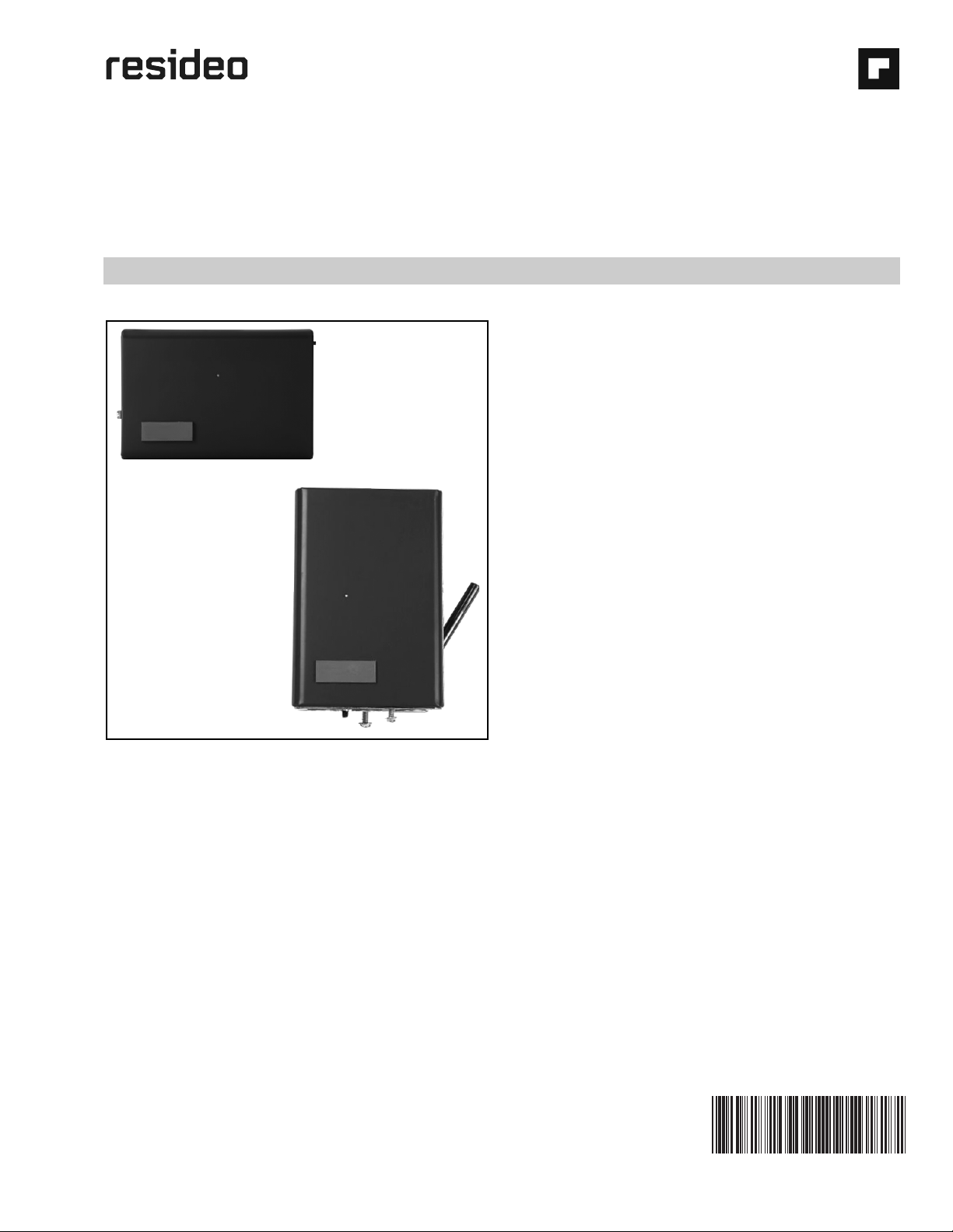
L8148A,E,J AQUASTAT® RELAYS
60-2278—10 4
Mounting
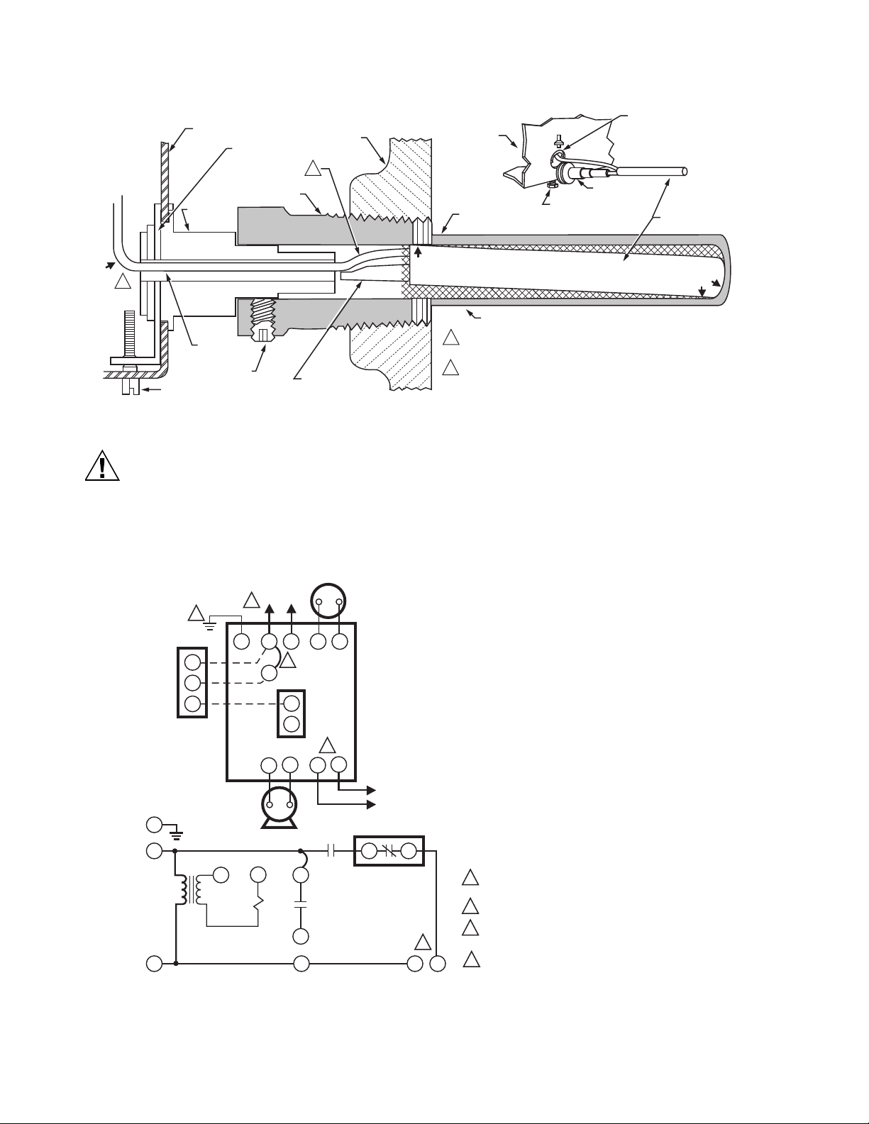
Boilers have tappings to allow immersion well (which must be
ordered separately) to be mounted horizontally so boiler water
of average temperature can circulate freely around the well.
1. Turn off all power and drain the boiler.
2. If no tapping is provided, prepare one properly sized and
threaded, and locate near the top of the boiler.
3. Coat the well threads sparingly with pipe dope, install
the well in the boiler tapping, and tighten securely.
NOTE: Do not attempt to tighten by using the case as
a handle.
4. Refill the boiler and check for water leakage.
5. Increase sensitivity of the bulb by coating with a good
heat-conductive compound. When used, coat the bulb
completely.
6. Insert the bulb element into the well until it bottoms. If
necessary, slightly bend the tube inside the case to hold
the bulb against the bottom of the well.
NOTE: Some models have a tubing length adjustable to 3 in.
(76 mm). In these models, pull out extra tubing from
inside the case, if needed.
7. Center the loop of excess tubing in front of the
immersion well so it cannot touch any electrical parts.
8. Fit the case onto the well so the clamp on the case
slides over the flange on the well. Tighten the clamp
screw securely.
IMPORTANT
Best thermal response is obtained with a well that
snugly fits the sensing bulb. For wells used, the bulb
should be inserted until it rests against the bottom of
the well. Use a well of correct length and bend the
tubing, if necessary, to hold the bulb against the
bottom of well, but do not make a sharp bend in the
tubing.
If the well does not fit snugly on the bulb, use the heat-
conductive compound as follows: Fold the plastic bag of
compound lengthwise and twist it gently. Then snip off the
end of the bag and work the open end of the bag all the way
into the well. Slowly pull out the bag while squeezing it firmly
to distribute the compound evenly in the well. Insert the bulb
all the way to the bottom of the well. Bend the tubing, if
necessary, to hold the bulb against the bottom of the well and
to hold the outer end of the bulb firmly in contact with the side
of the well (Fig. 4). Wipe excess compound off the outer end of
the well.
Wiring
IMPORTANT
Terminals on the L8148 Aquastat Relay are approved
for use with only copper wire. The terminals allow
only wrap-around wiring.
1.Strip 7/16 in. of insulation
from the wire end.
2.Wrap the wire at least 3/4 of
the distance around the screw
as shown.
3.Using a standard, flat-headed
screwdriver, tighten the screw
until the wire is snugly in
contact with the screw and contact plate.
4. Tighten the screw an additional one-half turn.
NOTE: Do not use a push-type ratchet screwdriver.
Disconnect power supply before making wiring connections
to prevent electrical shock or equipment damage.
All wiring must comply with local electrical codes and
ordinances. Do not exceed limits in the Specifications section
when applying this control.
When wiring a switch equipped with 1/4 in. tab terminal
connector, use 18 to 22 gauge wire with AMP Inc. part no.
2-520129-2 fully insulated flag receptacle connector or
equivalent.
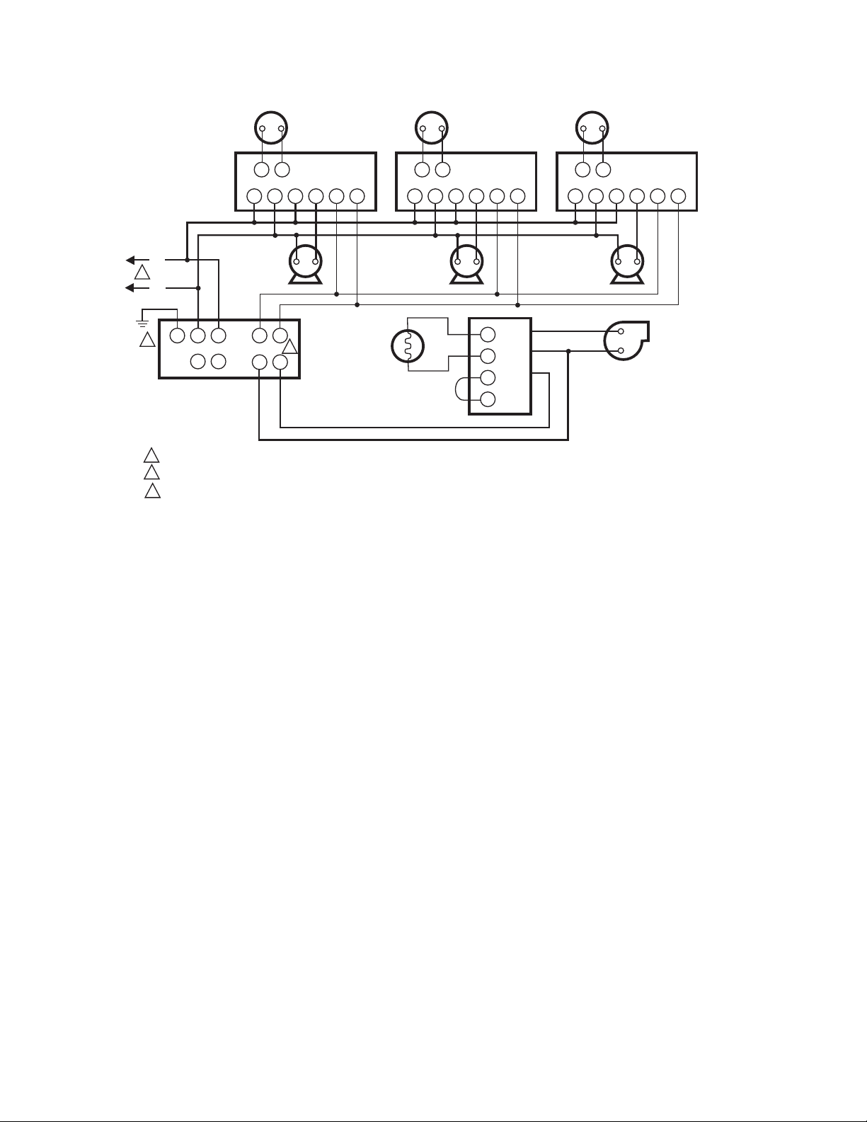
The L8148E,J can power up to two V8043 Zone Valves.
Additional valves, in groups of two or fewer, require an
additional transformer. Follow appropriate wiring diagrams,
see Fig. 5 through 14, when using zone valves or a low limit
controller.
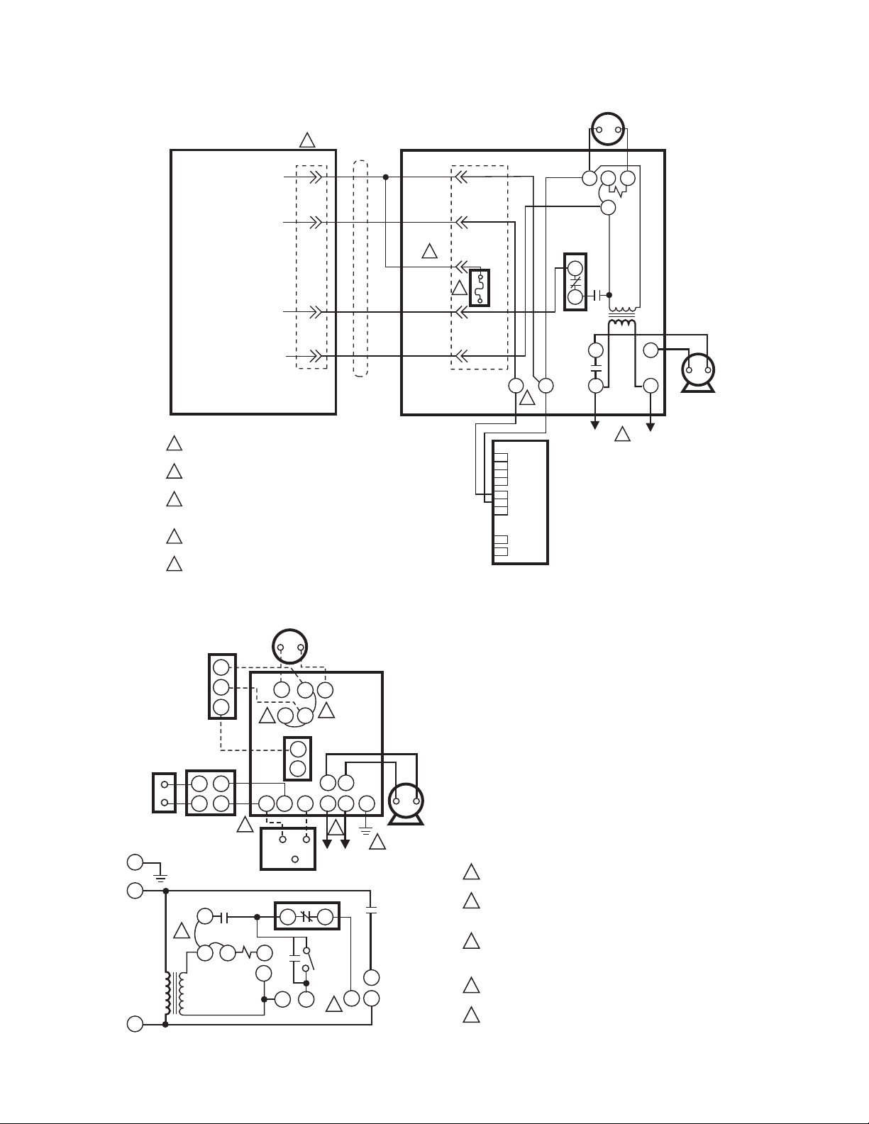
NOTE: On systems requiring a vent damper, the vent damper
can be connected directly to some L8148E Aquastat
Relay models (Fig. 12) or an S8610 Ignition Module
(Fig. 11).
When the vent damper is plugged into the Aquastat Relay, a
fuse in the Aquastat Relay will blow when the thermostat first
closes. Once the fuse is blown, the Aquastat Relay will not
operate unless the vent damper is connected.
When the vent damper is plugged into the Aquastat Relay, a
fuse in the Aquastat Relay will blow when the thermostat first
closes. Once the fuse is blown, the Aquastat Relay will not
operate unless the vent damper is connected.
With the vent damper plugged into the S8610, a fuse in the
ignition module will blow when first powered. Once the fuse is
blown, the ignition module will not operate unless the vent
damper is connected.