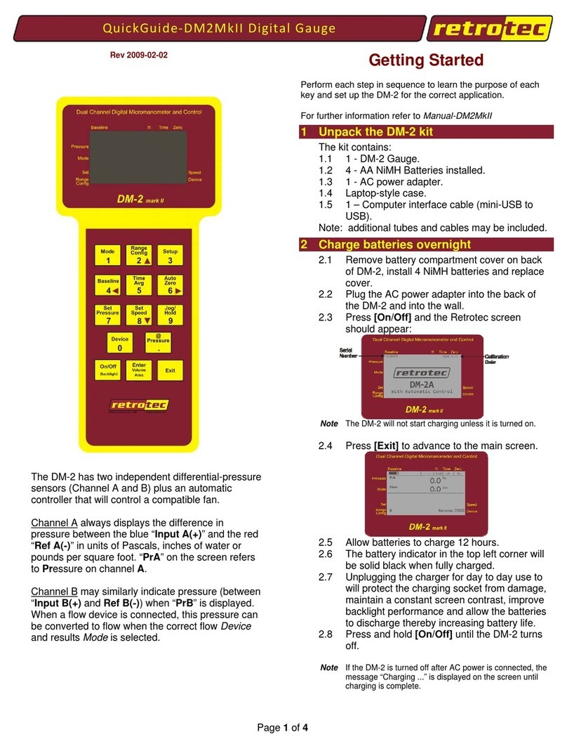
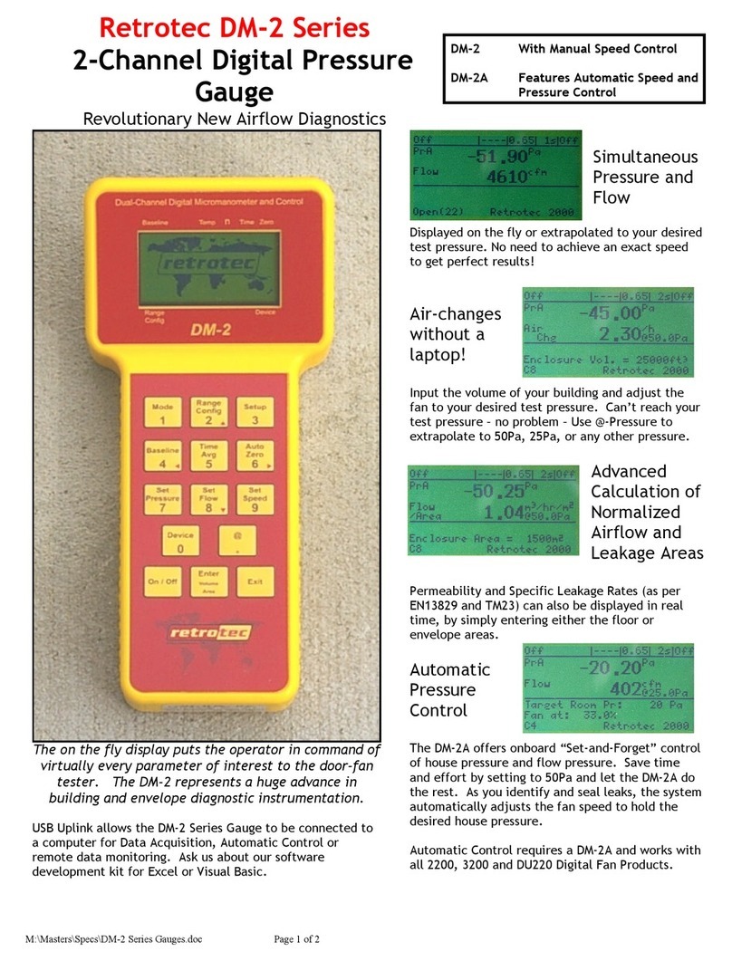
Retrotec DM-2 User manual

Retrotec Inc.
Operation Manual
Pressure Gauges
DM-2
rev-2013-12-02

Page 2 of 72
©Retrotec Inc. 2012
1DM-2 Digital Gauge Basics .................................................................................. 6
1.1 Gauge Overview .................................................................................................................. 6
1.1.1 The Connections Panel............................................................................................................................6
1.1.2 The DM-2 Screen ....................................................................................................................................7
1.1.3 The Keypad.............................................................................................................................................8
1.2 Batteries .............................................................................................................................. 8
1.2.1 Install batteries .......................................................................................................................................8
To install batteries for the first time.....................................................................................................................8
1.2.2 Charging batteries...................................................................................................................................9
1.2.3 Operating on Rechargeable batteries ......................................................................................................9
1.2.4 Rechargeable or non-rechargeable (alkaline) batteries ............................................................................9
1.2.5 Replacing batteries .................................................................................................................................9
To select proper battery type.............................................................................................................................10
1.2.6 View the remaining battery power ........................................................................................................10
1.3 Resetting the Gauge .......................................................................................................... 10
To reset a DM-2 with the Reset button ..............................................................................................................10
To reset a DM-2 without using the Reset button................................................................................................11
1.4 Screen Contrast ................................................................................................................. 11
To change the screen contrast ...........................................................................................................................11
2DM-2 Keypad Functions .................................................................................... 12
2.1.1 On/Off (Backlight) ................................................................................................................................12
2.1.2 Exit ....................................................................................................................................................... 12
2.1.3 Enter (Volume/Area).............................................................................................................................12
2.1.4 Device...................................................................................................................................................12
2.1.5 Mode....................................................................................................................................................13
2.1.6 Range Config.........................................................................................................................................13
2.1.7 Setup ....................................................................................................................................................14
Copyright © 2012 Retrotec Inc.
All rights reserved.
This document contains materials protected under International and Federal Copyright Laws. This book contains material
protected under International and Federal Copyright Laws and Treaties. Any unauthorized reprint or use of this material is
prohibited. No part of this book may be reproduced or transmitted in any form or by any means, electronic or mechanical,
including photocopying, recording, or by any information storage and retrieval system without acknowledging Retrotec Inc.
as the original source.
Retrotec makes no warranties with respect to this documentation and disclaims any implied warranties of merchantability,
quality, or fitness for any particular purpose. The information in this document is subject to change without notice.
Retrotec reserves the right to make revisions to this publication without obligation to notify any person or entity of any such
changes.
Infiltrometer, FanTestic, and DucTester are Trademarks of Retrotec Inc. Other Trademarks or brand names mentioned
herein are trademarks or registered trademarks of their respective owners.

Page 3 of 72
©Retrotec Inc. 2012
2.1.8 Baseline ................................................................................................................................................14
To establish a baseline pressure.........................................................................................................................14
2.1.9 Time Avg............................................................................................................................................... 15
2.1.10 Auto Zero .........................................................................................................................................15
2.1.11 Set Pressure...................................................................................................................................... 15
To use the Set Pressure function........................................................................................................................15
2.1.12 Set Speed .........................................................................................................................................16
To use the Set Speed function............................................................................................................................16
2.1.13 Jog/Hold ...........................................................................................................................................16
To activate Hold: ...............................................................................................................................................16
In Set Speed ...................................................................................................................................................... 17
In Set Pressure...................................................................................................................................................17
2.1.14 @ Pressure .......................................................................................................................................17
In Set Speed mode.............................................................................................................................................17
In Set Pressure mode......................................................................................................................................... 18
Example #1 - Inaccuracy ....................................................................................................................................18
Example #2 –Cannot reach desired pressure in Set Speed mode .......................................................................18
Example #3 –Display results at any pressure. ....................................................................................................18
3Set the Gauge up with only the Devices and results you use regularly ............ 19
3.1 Setup Menu ....................................................................................................................... 19
3.1.1 Full Screen Timeout ..............................................................................................................................20
To change the Full Screen Timeout time period..................................................................................................20
3.1.2 Restore Settings....................................................................................................................................20
To restore the factory settings........................................................................................................................... 20
3.1.3 Language ..............................................................................................................................................21
To change the language.....................................................................................................................................21
3.1.4 Battery Type .........................................................................................................................................21
To select a battery type .....................................................................................................................................21
3.1.5 Display Version Info ..............................................................................................................................21
To view version information ..............................................................................................................................21
3.1.6 n setting for estimating flow @ pressure during house and duct leakage test ........................................22
To change the n value........................................................................................................................................23
3.1.7 Power Down Hour................................................................................................................................. 23
To change the Power Down Hour.......................................................................................................................23
3.1.8 Surface Area Unit..................................................................................................................................24
To change the Area units ...................................................................................................................................24
3.1.9 Building Volume Unit ............................................................................................................................ 24
To change the Volume units ..............................................................................................................................24
3.1.10 European, Separator.........................................................................................................................24

Page 4 of 72
©Retrotec Inc. 2012
To change the European Separator units............................................................................................................25
3.1.11 Sig Figs.............................................................................................................................................. 25
To change the number of Significant Figures......................................................................................................25
3.2 Device Setup...................................................................................................................... 25
3.2.1 Enable and Disable Devices ...................................................................................................................27
To enable/disable Devices .................................................................................................................................27
3.2.2 Enable and Disable Range Configurations.............................................................................................. 27
To enable/disable Flow Range configurations in Device [Setup] .........................................................................28
3.3 Mode Setup ....................................................................................................................... 28
To configure Modes:..........................................................................................................................................29
4Understand the Pressure Gauge ....................................................................... 30
4.1 Differential Pressure.......................................................................................................... 30
To measure a pressure ......................................................................................................................................30
4.2 Positive vs. Negative Pressure ........................................................................................... 30
Measure a negative pressure.............................................................................................................................31
4.3 Analog Magnehelic Gauges ............................................................................................... 31
Retrotec’s magnehelic gauge system (right).......................................................................................................32
5Reduce Bias pressures, static or fluctuating ..................................................... 33
Reduce fluctuating pressures created by wind.............................................................................. 33
6Reduce uncertainty in results by taking lots of readings .................................. 35
7Check your gauge to see if it needs to be sent to factory for re-calibration .... 36
7.1 Verify your gauge calibration between factory calibrations.............................................. 36
To perform a tubing check.................................................................................................................................36
To perform a cross port check............................................................................................................................37
To perform a T-connection Fan Pressure check ..................................................................................................38
To perform a syringe check (not as good as the cross-channel check)................................................................. 38
8Use the Gauge with a calibrated fan for air leakage testing............................. 40
8.1 Making the Connections .................................................................................................... 40
8.1.1 Pressure port connections.....................................................................................................................40
8.1.2 Control connections..............................................................................................................................41
To connect the gauge to a Retrotec fan or variable speed fan drive.................................................................... 41
To connect the gauge to a Minneapolis Model 3 or Model 4 Fan ........................................................................42
8.2 Control a fan with the gauge to measure pressure and flow............................................. 42
To conduct a basic pressure test and ensure your gauge is working.................................................................... 42
8.3 Measure Air Handler flow using Hole Flow on the gauge.................................................. 43
To create an Exhaust Fan Flow Meter ................................................................................................................43
9Troubleshooting................................................................................................ 45
9.1 Check if moving tubes are causing fluctuating pressure .................................................... 45
To see the effect of a moving tube..................................................................................................................... 46

Page 5 of 72
©Retrotec Inc. 2012
9.2 Check if wind is causing fluctuating pressure .................................................................... 46
9.2.1 Use the [@ Pressure] key to reduce the effects of wind.........................................................................46
9.2.2 Use Time Averaging feature to reduce the effects of wind..................................................................... 47
[Time Avg] exercise to practice reducing the effects of wind ..............................................................................47
9.2.3 Use Baseline feature to reduce the effects of a constant wind............................................................... 47
[Baseline] exercise to practice minimizing the effects of wind ............................................................................47
9.2.4 In extreme cases you can use a Wind Damping Kit designed to reduce wind-related fluctuations...........47
No cost wind damping procedure ......................................................................................................................48
9.3 Let Time Averaging take effect before making readings.................................................... 48
To learn how Time Averaging can cause error ....................................................................................................49
9.4 Check if large fixed errors are caused by pinched tubes.................................................... 49
9.5 Check if large fixed errors are caused by water in the tube............................................... 49
9.6 Check if large fixed errors are caused by sun heating the tubes........................................ 50
9.7 Results will be wrong if the Range and Device being used are different than those selected
on the gauge.................................................................................................................................. 50
To determine correct flow if Range selected was different than the actual Range used: .....................................50
9.8 Fans without reference tube have results adjusted by gauge ........................................... 51
9.9 Pressure can overshoot when using the Set Pressure key ................................................. 51
9.10 Keep the Keep Rechargeable Batteries in top shape ......................................................... 52
To charge the batteries:.....................................................................................................................................52
9.11 If the Serial Number and Calibration Date are not valid.................................................... 53
9.12 If the keys on the DM-2 Keypad are not working .............................................................. 53
To fix the keypad if the keypad cable has come loose and keys are not working .................................................53
9.13 Updating Firmware............................................................................................................ 54
9.13.1 Firmware Changes ............................................................................................................................54
Table 10: Firmware changes from versions prior to 2.29 to the current version 3.01b. .......................................54
Appendix A: The gauge calculates Flow based on Pressure readings from the fan ..... 56
To determine the flow for a particular fan pressure FP:...................................................................................... 57
Check that the measured value for FP meets the two conditions based on MF and K2. If so, find the N, K, K1, and
K3 values in Table xxx (based on the type of fan and the Range Configuration being used), enter those values
along with the values measured for FP, and RP into the Flow equation stated above and calculate the result.....57
Appendix B: Manually calculate Flow if required test pressure cannot be reached.... 60
Cannot Reach 50 Pa Factors .......................................................................................................... 60
Cannot Reach 25 Pa Factors .......................................................................................................... 61
Appendix C: Errors occur in estimated flow if gauge and actual “n” don’t match....... 63
Appendix D: Adjust Flow values for temperature difference ...................................... 65
Appendix E: Tables to correct Flow if range selected did not match installed range .. 67
Appendix F: Setting up for a test with Alaska’s AkWarm software .............................. 69
Glossary......................................................................................................................... 70

Page 6 of 72
©Retrotec Inc. 2012
DM-2 Digital Gauge Basics
The DM-2 is Retrotec’s two channel digital micromanometer, or differential pressure gauge. It
combines simple but comprehensive functionality, with intuitive
controls and setup. The DM-2 is a dual channel digital gauge that
always displays a pressure on Channel A, but will display either
measured pressure on Channel B, or calculate flow, air changes per
hour, leakage area and display that on Channel B depending on the
Mode selected. To ensure accurate results, the DM-2 takes up to four
pressure readings per second on each channel, and updates the
information displayed on the screen every second.
1.1 Gauge Overview
The Retrotec DM-2 mark II gauge has: a connections panel, a display
screen, and a keypad. The connections panel on the back of the gauge is where all external devices are
connected to the DM-2. The display provides information on the current test mode and/or setup, as
well as the device status and measurement values. The keypad is where the user inputs data to the
DM-2, and operates the DM-2 functions.
1.1.1 The Connections Panel
Figure 1: DM-2 back panel with pressure ports and electrical connections
Electronic function:
1. Control fan speed. (NOT for Internet
connection)
2. Mini USB connection to a PC
3. Reset button
4. Battery charger input
Pressure Ports:
5. Input B (+)
6. Reference B (-)
7. Reference A (-)
8. Input A (+)

Page 7 of 72
©Retrotec Inc. 2012
The Fan Speed Control output on the gauge cable uses RS-485 protocol. The Speed Control Cable can
thus extend approximately 1,200 metres (4,000 feet) between the gauge and the fan.
1.1.2 The DM-2 Screen
The Display Screen is where all measurement values are shown, as well as the current status of the
device, and test configuration.
Table 1: DM-2 Gauge Screen
Key
Description
Page for
more
information
Battery Health
/Baseline Value
Displays the battery health (degree of charge) for rechargeable batteries
only.
If “Baseline” has been activated, a pressure will appear that is deducted
from the “PrA”value.
17
Jog/Hold
Cycles between inactive as indicated by "- - - - " and "Hold" which will
hold the display and control functions until “Hold” is turned off. “Jog”
will be possible when using Set Speed or Set Pressure.
19
n
Displays the current value of the slope of the line along which
@Pressure estimates are extrapolated. Can be set between 0.50 and
1.00. A value of 0.65 is suggested for houses, 0.60 for ducts and 0.55 for
leaky buildings with large holes and for large buildings.
27
Time
Displays the current Time Averaging setting: Off, 1s, 2s, 4s, 8s, 10s, 20s,
1m, 2m.
18
Zero
Displays the current Auto Zero status, On or Off.
18
Volume/Area
Input
Displays the current surface area, or enclosure volume setting, used for
calculations involving per unit area.
15
Speed
Displays the current fan speed as a percentage
19
Device
Displays the current fan (also known as the Device). This must match
the fan that is in use.
15

Page 8 of 72
©Retrotec Inc. 2012
Range Config
Displays the Range configuration. The Range selected must match the
Range that is in use on the fan.
16
Set
Displays either the Set Pressure for Channel A or the Set Fan Speed that
the gauge will attempt to reach.
18
19
Pressure
Displays the pressure difference between the “Input A” (blue) port and
the “Ref A” (red) port. Units shown at “Channel A Result” are chosen
using [Setup]
Mode
Displays the current results being calculated by the gauge (being shown
on “Channel B Result”). “Channel B Result” depends on the pressure
difference between the “Input B” (green) port and the “Ref B” (yellow)
port (usually connected to the fan) and other parameters entered into
the gauge.
16
1.1.3 The Keypad
The DM-2 keypad provides access to all DM-2 settings and controls.
Some keys have multiple functions. Keys labeled with an arrow [], [], [], and []can be used to
navigate around the menus, to change the current selection, and are active as arrows when using the
[Setup] menus or when “Jog” is being used. Pressing and holding a key automatically repeats the
keystroke, and this feature can be used to scroll through menus more quickly.
1.2 Batteries
The DM-2 can draw power from an AC power supply through a
2000 or 3000 fan, directly from the charger plugged into a wall
outlet, or from four AA batteries.
1.2.1 Install batteries
The DM-2 comes with four AA NiMH rechargeable batteries.
To install batteries for the first time
1. Using a small Phillips screwdriver, open the lower back
panel of the DM-2.
2. Install the four AA rechargeable NiMH batteries,
making sure to align them correctly, and ensuring that

Page 9 of 72
©Retrotec Inc. 2012
the contacts are secure against both the positive and negative ends of each battery.
3. Replace the battery compartment panel and securely tighten the screw.
4. Plug the AC power adapter into a wall outlet and into the DM-2 DC power receptacle.
5. Turn the gauge on.
6. Allow the batteries to charge until the charging is
complete (according to the battery status indicator).
This may take up to 24 hours.
Caution: Do not open the panel labeled “No User Serviceable Parts Inside. Do Not Open.” Doing so will
void the calibration and warranty.
1.2.2 Charging batteries
The batteries can be charged in the DM-2 with the AC power adapter, or in a compatible battery
charger. The batteries should be charged for at least 8 hours each time. To completely charge the
batteries, prior to using the gauge for the first time, 24 hours may be required. If the battery charge
indicator is not moving then chances are the Setup needs to be set to “Rechargeable” under “Battery
Type”. When "Not Rechargeable" is selected, the batteries, regardless of type, will not be charged.
Attempting to charge non-rechargeable batteries can cause the batteries to leak, permanently
damaging the DM-2.
The DM-2 includes the ability to recharge the batteries inside the gauge. The batteries will not start
charging if the DM-2 is not turned on first (i.e. you must turn on the DM-2 first, and then plug in the
AC power supply to charge the batteries).
1.2.3 Operating on Rechargeable batteries
It is recommended that the gauge be used on battery power when possible. When battery power is
insufficient to power the gauge, the warning message "Battery Too Low" will appear on the screen.
To prolong battery life, recharge the batteries only when they reach ¼ power
(displayed on the battery status indicator). Do not operate the DM-2 with the
AC power adapter or the Umbilical power cord attached after they are fully
charged; this will significantly shorten the lifespan of rechargeable batteries. If the DM-2 must be
operated with AC power, remove the batteries to prevent the shortening of the battery lifespan. The
batteries are fully charged when the battery indicator is solid black. Allow the batteries to occasionally
discharge completely to improve battery life.
The standard NiMH batteries that are included with the DM-2 should last for two years of constant
use. Extend the life of your batteries by placing them in a quality charger every six months.
1.2.4 Rechargeable or non-rechargeable (alkaline) batteries
Non-rechargeable batteries can also be used, but the charging circuit should be disabled to prevent
accidental charging. Charging an alkaline battery may cause it to explode or leak.
1.2.5 Replacing batteries
Batteries must always be from an identical set where all batteries have exactly the same history. Do
NOT use mismatched batteries. Usually, rechargeable batteries are used and the Setup menu must say

Page 10 of 72
©Retrotec Inc. 2012
“Rechargeable” under “Battery Type” otherwise the charger will not work. If you choose to use non
rechargeable batteries such as Lithium Ion, ensure the “Battery Type” is set to “Not Rechargeable”.
1. Using a small Phillips screwdriver, open the lower back panel of the DM-2.
2. Remove the four old AA batteries and recycle them at a participating collection center.
3. Install four new AA batteries, making sure to align them correctly, and ensuring that the
contacts are secure against both the positive and negative ends of each battery.
4. Replace the battery compartment panel and securely tighten the screw.
If a different type of battery is used (i.e. change from rechargeable to non-rechargeable), make sure to
change the battery type in the Setup Menu of the DM-2.
To select proper battery type
1. Press [Setup].
2. Scroll to "Battery Type" and select "Rechargeable" or "Not Rechargeable" as needed.
3. Press [Exit].
1.2.6 View the remaining battery power
The DM-2 features a battery health indicator, displaying the current status of the battery on the main
screen. The indicator is located in the upper-left corner of the display.
1. Turn the gauge on by pressing [On/Off].
2. The splash screen is displayed.
3. Press [Exit] to view the main screen. The battery power indicator is in the top left.
Figure 2: Splash screen and the main screen with battery life indication in the top left.
Batteries will last longer if the backlight and auto-zero features are turned off, and if the gauge is
manually turned off when not in use.
1.3 Resetting the Gauge
If the DM-2 ever becomes frozen, or stops responding, it can be reset. Depending on the age of the
gauge, there are two ways to reset a gauge.
To reset a DM-2 with the Reset button
1. Press the Reset button. (The Reset button is located at the back of the gauge)
2. The gauge should turn on.
3. If pressing the Reset button on the DM-2 fails to reset the gauge, the batteries may need to
be replaced or plugged into DC supply

Page 11 of 72
©Retrotec Inc. 2012
To reset a DM-2 without using the Reset button
1. Remove the back panel labeled "Battery Compartment".
2. Remove the batteries, and disconnect all other tubes or cords.
3. Wait five minutes.
4. Re-install the batteries.
1.4 Screen Contrast
Older model DM-2 gauges include the ability to change the screen contrast in order to improve
visibility in different light conditions. Newer models have the voltage to the screen regulated so the
contrast adjustment is not necessary.
To change the screen contrast
1. If required, insert a small Phillips head screwdriver into the hole on the back marked "LCD
Contrast".
2. Adjust the dial until the desired screen contrast is achieved.

Page 12 of 72
©Retrotec Inc. 2012
2DM-2 Keypad Functions
The DM-2 Keypad has 14 keys which control all of the DM-2 functions.
2.1.1 On/Off (Backlight)
The On/Off (Backlight) key turns the gauge on and off, and allows the user to turn on
the backlight, or preserve battery life and turn it off.
Press [On/Off] to turn the DM-2 on. The key needs to be held down for two seconds
to turn the gauge off. The DM-2 is equipped with a backlight to improve visibility. The backlight turns
on for a brief time when any key is pressed. When the DM-2 is on, pressing [On/Off] briefly will turn
the backlight on permanently. Pressing it quickly again will turn the backlight off.
2.1.2 Exit
The Exit key allows the user to exit from certain screens, stop the fan, and clear entries.
Press [Exit] after turning the gauge on, in order to clear the splash screen. When in a
Setup Menu, press [Exit] to back out of the current menu screen, or to cancel a menu
selection. While in Set Pressure or Set Speed mode, press [Exit] to immediately turn off the fan (the
fan can also be stopped by setting the speed to zero). Pressing [Exit] at any time while in the main
screen will cancel the Baseline as well.
2.1.3 Enter (Volume/Area)
[Enter] is a multi-application key that applies to several functions. Press [Enter] to
select menu items, or to save input values. Depending on the Mode in use, a volume
or area value may be required (Volume for Air Changes per hour, Area for any of the
“per Area” results). Press [Enter] while the volume or area result is selected, to activate data entry for
volume or area. Enter the appropriate value and press [Enter] again to save.
2.1.4 Device
“Device”refers to the fan or pressure measuring device being used to conduct the
current test. It is important to make sure that the correct Device is selected; because
the calculations for each of the results are based on system flow equations that are
different for each Device.
Press [Device] to switch between the devices that have been enabled on the DM-2. Only the devices
that have been enabled in the Setup Menu can be selected with the Device key. The currently selected
Device is displayed on the bottom right corner of the screen. The Devices that can be selected for use
with the DM-2 are listed in Table 5. See Section 3.2 Device Setup for instructions on how to enable or
disable Devices.
Ranges available for each Device can be enabled or disabled so they show as choices when the [Range
Config] key is used. Use the “Setup” menu to enable or disable the Ranges associated with each
Device. See Enable and Disable Range Configurations in Section 3.2 for detailed instructions.
When numerical input is required, the [Device] key is used to input the number zero, [0].

Page 13 of 72
©Retrotec Inc. 2012
2.1.5 Mode
“Mode” refers to the measurements and results the DM-2 mark II can display. Each
Mode can also display in a variety of units. The top result line labeled “Pressure”
always displays Channel A pressure in the units chosen for “Pressure”. The second
result line labeled “Mode” displays the selected result in the chosen units. For information on setting
units for each Mode, see Section 3.3 Mode Setup. Table 2 lists all the Modes, the possible units that
can be set on the DM-2, and what the results mean (note that some results and units are not available
on all gauge models).
Table 2: Possible results and selectable units for the gauge
Mode
Measures
Units
Pressure
Fan Pressure through the fan
Pa, inches WC, lb/sq ft
Flow
Air flow through the fan
CFM, l/s, m3/s, m3/h
EfLA
Effective Leakage Area –calculated size of the total
hole in the Envelope. Usually taken at 4Pa in the US
cm2, sq in, sq ft
EqLA
Equivalent Leakage Area –calculated size of the total
hole in the Envelope. Usually taken at 10Pa in Canada
cm2, sq in, sq ft
Air Change
Number of air changes per hour
/h
Flow/Area
Air flow divided by the area of the enclosure
CFM/ sq ft, L/s.m2, CFM/100 sq ft,
m3/h.m2
EfLA/Area
Effective Leakage Area divided by enclosure area
sq in/100 sq ft, cm2/m2
EqLA/Area
Equivalent Leakage Area divided by enclosure area
sq in/100 sq ft, cm2/m2
Hole Flow
The flow across a hole –to be used to measure flow
through a known hole size (like exhaust fan or register)
CFM, L/s, m3/s, m3/h
Velocity
Air velocity (requires pitot tube)
m/s, km/h, ft/s, ft/min, mph
Velocity Flow
Flow from velocity and area of duct
CFM, L/s, m3/s, m3/h
Press [Mode] to scroll through the results that have been activated in the Setup menu. If all modes are
activated then pressing [Mode] will cycle through the results in the following order:
Pressure Flow EqLA EfLA Air Changes Flow/Area EqLA/AreaEqLA/Area
Hole Flow Velocity
Velocity Flow
Older gauges have the velocity and velocity flow function.
When numerical input is required, the [Mode] key functions to input the number one, [1].
2.1.6 Range Config
Range Rings and Plates are used to limit the air flow through a fan, so that the fan can
achieve a measurable Fan Pressure, even when moving only a small amount of air (for
more information, see Manual - Door Fan Operations). Every fan that the gauge is
compatible with has a set of associated Range Configurations. Select the Range Configuration that
matches the Range Ring or Plate installed on the fan attached to the gauge to ensure that the gauge
performs accurate calculations, and displays correct results. Press [Range Config] to cycle through the
Range Configurations that are available for the currently selected device. Available Range
Configurations that are not used can be removed from the menu. See Enable and Disable Range
Configurations in Section 3.2 for detailed instructions.
When numerical input is required, the [Range Config] key functions to input the number two, [2].

Page 14 of 72
©Retrotec Inc. 2012
2.1.7 Setup
The [Setup] key allows access to the “Setup”Menu, where the gauge is customized.
Setup is used to enable or disable each of the various result display Modes and Devices,
to configure the units of measurement for each result Mode, and to configure other
parameters for the operation of the gauge. To navigate around the setup menu, use
the up or down arrows [] and []to scroll through the menu. Use the left or right arrows [] and
[]to choose between the different options. The configuration is saved in non-volatile memory so the
gauge will have the same configuration each time it is turned on.
The “Setup”menu provides access to the following settings:
Full Screen Timeout –specify the time before the screen changes to the full screen format
Restore Settings –restore the gauge to factory settings
Language –choose a language for the gauge menus and results
Battery Type –choose between rechargeable and non-rechargeable (alkaline)
Display Version Info –view the system version information
n –set the slope of the line that the gauge will use to extrapolate results, when using the
@Pressure function
Power Down Hour –set the number of hours after which the gauge will automatically turn off
Surface Area Unit –specify the units that will be used for enclosure area
Building Volume Unit –specify the units that will be used for enclosure volume
European , Separator –specify whether to use a comma in place of a period in the numbers
displayed
Sig Figs –Select one of 2.5, 3.0, or 3.5 significant figures (e.g. 1134 is displayed as 1135 for “3.5”,
1130 for “3.0”, and 1150 for “2.5”)
Device Setup –enable or disable the use of compatible devices and their associated Range
Configurations
Mode Setup –enable or disable result Modes displayed and specify the units for enabled Modes
When numerical input is required, the [Setup] key functions to input the number three, [3].
2.1.8 Baseline
The Baseline function allows the user to measure the bias pressure, or Baseline
pressure, under the current test conditions. Once measured, the gauge will
automatically subtract the baseline pressure from all subsequently measured pressure
readings, and will display only the adjusted pressures on the screen. Some buildings
have an initial pressure imbalance between the indoors and outdoors, prior to any testing. The gauge
averages the background pressure for the duration of the acquisition period. A 60 second baseline
reading is typically enough to establish an accurate baseline measurement. If the building conditions
change during the test, the baseline should be cleared and a new measurement should be taken.
Remember, if [Exit] is pressed to stop the fan, the baseline measurement will also be cleared, and will
need to be re-taken.
To establish a baseline pressure
1. Press [Baseline] to begin acquiring the baseline or bias pressure. The gauge displays
“acquiring”and begins to sample the baseline pressure. While acquiring the pressure value,

Page 15 of 72
©Retrotec Inc. 2012
the gauge will continuously display the updated average pressure, and the sampling
duration on the screen. The more the pressure is fluctuating, the longer the baseline will be
sampled for.
2. Press [Enter] to accept the current measurement, usually after approximately 60 seconds.
If there is a lot of fluctuation, let the baseline acquire for longer than 60 seconds. The
current baseline measurement, and the time taken to acquire it, is displayed at the bottom
of the Main Screen.
3. Pressing [Exit] will clear the measurement.
When numerical input is required, the [Baseline] key functions to input the number four, [4].
2.1.9 Time Avg
When Time Averaging is active, the gauge will display results and pressures that are
averaged over the time period selected, on both channels. Regardless of the averaging
value, the display will update with a new value every second. This can provide
significantly more accurate results.
The gauge includes nine time averaging settings. Press [Time Avg] to scroll through the following time
averaging settings: Off, 1s, 2s, 4s, 8s, 10s, 20s, 1m, and 2m.
Caution: When changing the fan speed, set pressure, or taking a reading after making any other
changes, wait for twice the time averaging period to elapse before taking a reading. Taking a reading
too quickly can lead to recording incorrect results.
Notice that the [Time Avg] key is located in the middle of all the arrow keys on the keypad. As a user
friendly feature, while in the Setup Menu, the [Time Avg] key can be used to select menu items, just as
you would using the [Enter] key.
When numerical input is required, the [Time Avg] key functions to input the number five, [5].
2.1.10 Auto Zero
Over time, the reading on Channel A and Channel B will start to drift away from zero.
The longer the gauge is turned on, the larger this error can become. With Auto Zero
on, the gauge will automatically zero the gauge every 8 seconds. In general, the DM-2
should be used with auto zero feature on. However, the function does consume extra
battery power. Turning auto zero on, only at the start of each data acquisition cycle, will maximize
battery life, gauge performance and data transfer rates.
Press [Auto Zero] to turn the Auto Zero function on or off.
When numerical input is required, the [Auto Zero] key functions to input the number six,[6].
2.1.11 Set Pressure
The gauge can automatically control the fan speed on Retrotec systems to achieve a
user chosen building pressure. This is the easiest method to achieve a specific test
pressure.
To use the Set Pressure function

Page 16 of 72
©Retrotec Inc. 2012
1. Press [Set Pressure] to activate the automatic control. Input the desired building pressure
using the DM-2 keypad and press [Enter] to start the fan.
2. The fan will accelerate until the input pressure has been reached, or the fan reaches 100%
speed. The fan will continue to hold at that pressure, regardless of changes to the
enclosure or room (i.e. opening/closing windows and doors, HVAC on/off, sealing, etc.).
3. Press [Exit] to stop the fan, and cancel the Set Pressure.
If the pressure is set to “0” Pa, the gauge will adjust the fan speed to bring the existing pressure to
zero. This can be used to neutralize pressures during specific tests. See the Retrotec DucTester
Operation & Testing manual for an example.
When numerical input is required, the [Set Pressure] key functions to input the number seven, [7].
2.1.12 Set Speed
The gauge can automatically control the fan speed on Retrotec systems to achieve a
specific user-defined fan speed.
To use the Set Speed function
1. Press [Set Speed] to activate the automatic control.
2. Input the desired speed using the DM-2 keypad. Speed is input as a percentage, and can be
any value from 1-100.
3. Press [Enter] to start the fan. The fan will accelerate until the desired speed is achieved.
4. Press [Exit] to stop the fan and cancel the Set Speed, or press [Set Speed] [0] [Enter] to stop
the fan.
When numerical input is required, the [Set Speed] key functions to input the number eight, [8].
2.1.13 Jog/Hold
The [Jog/Hold] key has two functions, Holding the display and Jogging the fan speed:
2.1.13.1 Hold
Freezes the display with the data currently displayed on the screen. Nothing will
change until the [Jog/Hold] key is pressed again to clear "Hold".
Can be activated at any time.
Allows the recording of instananeous results (eg. Flow, EqLA, PrB at precisely the same time)
Hold will also hold the Speed Control signal to the fan without allowing it to vary up or down. The
signal will be held until [Exit] is pressed which will shut off the fan.
The screen will display either "- - - - " or "Hold", unless it is doing a Set Speed or Set Pressure when it
will display either "- - - - ", "Jog" or "Hold".
To activate Hold:
1. Press [Jog/Hold] until "Hold" appears on the screen to freeze the screen and lock the data
currently displayed.
2. Press [Jog/Hold] again until "----" is displayed to unlock the screen.

Page 17 of 72
©Retrotec Inc. 2012
2.1.13.2 Jog
Jog functions differently depending on whether the gauge is setting pressure or setting speed.
Enables the keypad arrows []or []to adjust the Set Speed or Set Pressure up or down much
like a traditional remote control.
The screen will display either "- - - - ", "Jog" or "Hold" (when in Set Speed or Set Pressure mode).
When not in Set Speed or Set Pressure mode, the DM-2 will not enter Jog mode (but Hold mode
can be activated at any time).
In Set Speed
1. Press [Jog/Hold] until "Jog" appears on screen.
2. Press []or []to increase or decrease the set speed in 1% increments.
3. Press and hold []or []to increase or decrease the set speed in 5% increments.
4. Press [Jog/Hold] again until "----" is displayed to resume normal operation.
In Set Pressure
1. Press [Jog/Hold] until "Jog" appears on screen.
2. Press []or []to increase or decrease the set pressure in increments of 5 Pa, 0.02 in WC,
or 0.105 lbs/sq ft.
3. Press and hold []or []to increase or decrease the set pressure in increments of 10 Pa,
0.04 in WC, or 0.21 lb/sq ft.
4. Press [Jog/Hold] again until "----" is displayed to resume normal operation.
When numerical input is required, the [Jog/Hold] key functions to input the number nine, [9].
2.1.14 @ Pressure
The [@ Pressure] key asks the DM-2 to calculate a result that would be achieved, if the
desired test pressure were measured. The measured pressure will almost always be at
least slightly over, or under, the exact test pressure making it difficult to report results
that are standardised for a specific pressure. The [@ Pressure] function performs a calculation called
"extrapolation" which analyzes the currently measured results, and displays the results as if the exact
test pressure was achieved.
Press [@ Pressure] to toggle the gauge pressure extrapolation function on and off. The test pressure
that is being extrapolated to is configured in the Setup Menu.
Note: While the gauge is capable of extrapolating to any pressure, it is most accurate when the actual
building pressure is closer to the desired extrapolation pressure.
The @ Pressure function provides unique advantages over un-extrapolated results:
There is no need to achieve an exact test pressure.
The results on the screen will be very stable since results are extrapolated to a specific pressure.
Results can be obtained, even if the test pressure cannot be reached, as long as the pressure
actually achieved is within 10% of the desired test pressure.
In Set Speed mode

Page 18 of 72
©Retrotec Inc. 2012
1. Press [@ Pressure] to view the results at a particular pressure, as set in the Setup Menu.
The units will change to indicate that @ Pressure is on (e.g. CFM@50.0Pa).
2. Press [@ Pressure] again to view the current (non-extrapolated) results. The units will
change to indicate that @ Pressure is off (e.g. CFM).
In Set Pressure mode
1. Press [@ Pressure] once to view the results at the current Set Pressure value. The units will
2. Press [@ Pressure] again to view the results at the @ Pressure, as set in the Setup Menu.
3. Press [@ Pressure] again to view the current (non-extrapolated) results. The units will
change to indicate that @ Pressure is off (e.g. CFM).
It is important to understand how to use this feature properly, as inaccurate results are likely if it is
used incorrectly. The extrapolation feature works by estimating a typical leakage constant, and using it
to calculate the results at the desired pressure. In general, if the desired test pressure is within +/- 10%
of the actual measured pressure, the @ Pressure will be accurate enough to record. This function
should only be turned on and made active when in the appropriate situation –do not leave it on for all
tests as this may lead to inaccuracies. Try the examples below to familiarize yourself with the
versatility of this function.
Example #1 - Inaccuracy
A 50 Pa building pressure is desired, but only 20 Pa can be reached (due to severe leakiness). In this
instance, the extrapolated results for flow “@ 50 Pa”do not represent the reality of the testing
conditions and might be highly inaccurate.
In the same situation, a 45 Pa building pressure is achieved. The extrapolated “@ 50 Pa”pressure is
now much more accurate, and provides an acceptable result.
Example #2 –Cannot reach desired pressure in Set Speed mode
With the fan set at 100% speed, a building pressure of 46 Pa is reached. Press [@ Pressure] once and
the flow that would occur at the default pressure (usually 50 Pa) is displayed. Each time the key is
pressed, the results alternate between displaying “CFM”and “CFM @50Pa”.This Default Pressure of
50 Pa can be changed in the Setup menu and will usually be the one you want results at most of the
time.
Example #3 –Display results at any pressure.
If you wish to display results at a different pressure, the fastest method is to use the [Set Pressure]
key. Press [Set Pressure] [75] and now pressing the [@ Pressure] key will cycle between; “CFM”, “CFM
@50Pa”, and “CFM @75Pa”.
When numerical input is required, the [@ Pressure] key functions to input the decimal point [.].

Page 19 of 72
©Retrotec Inc. 2012
3Set the Gauge up with only the Devices and results you use
regularly
While the gauge can be run using the default settings, configuring the gauge for a specific fan system
and testing protocol can save time and reduce the chance of making mistakes. Some systems may be
ordered with the correct settings for a specific region and for the equipment being used. The Setup
Menu provides access to a number of settings, including the Device and Mode Setup screens.
3.1 Setup Menu
The Setup Menu contains access to two sub-menus and a list of other setup options:
Table 3: Settings available on the gauge [Setup]
Setting
Default
Description
Full Screen Timeout
15
Time in seconds until the display becomes large –set to 0 if you never
want to use the large screen display option
Restore Settings
Set the gauge back to factory default settings
Language
English
Choose the display language on the gauge
Battery Type
Rechargeable
Tells the gauge whether or not to charge the batteries. If you change to
non rechargeable batteries be sure to set this to “Not Rechargeable” to
avoid damage
Display Version
Selecting this item shows the Version of the firmware, the chipset and the
date of last calibration (press [Exit] to get back to the Setup menu)
n
0.65
Set to 0.65 for house testing, 0.60 for ducts and 0.50 for air handler flow
measurements. Extrapolation factor used by the @ Pressure function
Power Down Hour
1
Set how many hours of inactivity need occur before the gauge powers
itself down to save battery life
Surface Area Unit
sq ft
Units to use with the entered value for Area
Building Volume Unit
cu ft
Units to use with the entered value for Volume
European , Separator
no
Use “,” instead of “. “ as the decimal point
Sig Figs
3.5
Set how many decimal points are used, and how the results are rounded
Device Setup
Access the Device Setup sub-menu to enable or disable devices (fans) to
choose only the Devices you use and thus limit the list of Devices that the
[Device] key scrolls through
Mode Setup
Access the Mode Setup sub-menu to choose which Results are available to
display on “Channel B Result”, and to choose the units for the results being
displayed

Page 20 of 72
©Retrotec Inc. 2012
Notice that the [Time Avg] key is located in the middle of all the arrow keys on the keypad. As a user
friendly feature, while in the Setup Menu, the [Time Avg] key can be used to select menu items, just as
you would using the [Enter] key.
3.1.1 Full Screen Timeout
Some DM-2 gauges, (firmware Version 3.0 or higher), have a large format screen which automatically
appears when no key press is recorded for a period of time. The length of time that must pass is
determined by the Full Screen Timeout setting.
To change the Full Screen Timeout time period
1. Press [Setup] to access the Setup menu.
2. Press []or []to select "Full Screen Timeout" in the list. Press [Enter].
3. Input a time (in seconds) between 0-120. Press [Enter]. Press [Exit].
The gauge will not display the large format screen if a time period of '0' is entered in the [Setup].
3.1.2 Restore Settings
At any time, the factory settings can be restored in the gauge. This will reset the gauge to have exactly
the same settings that the gauge had when it was produced at the factory.
To restore the factory settings
1. Press [Setup] to access the Setup menu.
2. Press []or []to select "Restore Settings" in the list.
3. Press []or []to select Yes.
Other manuals for DM-2
1
Table of contents
Other Retrotec Measuring Instrument manuals
Popular Measuring Instrument manuals by other brands

Tegam
Tegam R1M-A Operation and maintenance manual

Minolta
Minolta FLASH METER IV - PART 2 manual

Emerson
Emerson Rosemount 2051CF series quick start guide

MULTISPAN
MULTISPAN MS-1208A user manual

Veeder-Root
Veeder-Root EMR3 XStream-PKG Spring Installation Instructions

Seametrics
Seametrics iMAG 4700 instructions

Growatt
Growatt ShineWiFi-X manual

Leica
Leica RANGEMASTER 1200 scan Specifications

PCB Piezotronics
PCB Piezotronics IMI SENSORS 646B11 Installation and operating manual

Fuji Electric
Fuji Electric ZaFe instruction manual

BorMann
BorMann PRO BDM6500 user manual

National Instruments
National Instruments 9775 Getting started guide