IMAG 4700 INSTRUCTIONS
Seametrics • 253.872.0284 Page 18 seametrics.com
CONFIGURATION
Analog Output (4-20mA) Conguration. (Not available
on battery only units.) Since the meter’s analog output
is isolated and passive, loop power must be supplied
externally as shown previously. (In addition, an external
resistor RLwill be needed to convert the loop current to
voltage for voltage-only input devices.) The meter’s loop
transmitter minimum voltage drop is 6Vdc (8Vdc with
HART) which, with wiring resistance and loop power supply
voltage, will determine the maximum resistance for RL. The
ow rates corresponding to 4 and 20mA can be set by the
user via the SET 4 and SET20 tabs on the meter’s setup
menus.
HART Conguration. (Not available on battery only units.)
The HART protocol, rev.7.5, allows for a Polling address
between 0 and 63. The default value in the iMAG is 0. To
change the Polling address, use iMAG menu HPOLL to set
the Polling address.
To get to this menu, move to the EXIT tab and tap the left
button 4 times. This will bring up the SUBMENU page.
Navigate to the HPOLL tab. Use the left button to select
the Polling address.
To enter SUBMENU To select address
(See Changing Flow Meter Settings later in these
instructions for details in using the menu system.)
A minimum of 250 ohms of loop resistance must be present
in order for the HART modem to correctly and reliably
demodulate FSK voltage. With this in mind, the maximum
loop resistance* for the iMAG HART interface cannot be
exceeded in order to assure correct operation.
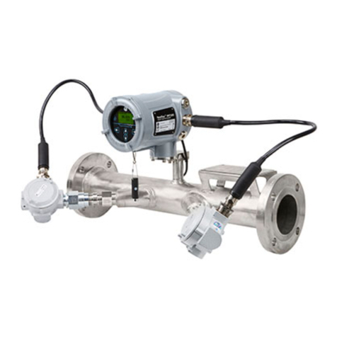
The iMAG HART interface is HART compatible. All the
commands have been implemented in accordance with
the HART Protocol Specication published by HART
Foundation. A HART Communicator can be used with the
iMAG, even in the absence of DD les, by taking advantage
of the Generic Online Menu capability of a Communicator.
This means that a generic menu is automatically available
when DD les are not present.
X 4
The following information from the iMAG HART can
be displayed on the Communicator using the generic
menu:
PV Flowrate in units selected for iMAG
PV Loop
Current
Loop current in mA
PV LRV Lower range value of PV in units
selected for iMAG
PV URV Upper range of PV in units selected
for iMAG
*4-20 mA loop has maximum loop resistance of 650ohms
and requires a 24Vdc power supply.
Modbus® Serial Communication Conguration (factory
congured). (Not available on battery only units.) These
connections provide a half-duplex, isolated, RS485 serial
communications port using the Modbus messaging
protocol. The port is recongurable by internal jumper
settings to full-duplex RS232 or 3.3V CMOS. The TXD
connection is the transmitted data output from the meter
and RXD is the received data input to the meter. See
Seametric’s Modbus Interface Description, LT-103393
(available at www.seametrics.com) for supported Modbus
message protocol and electrical interface specications.
Digital Output Conguration. (Not available on battery
only units.) These outputs are electrically similar to the Pulse
Output described above except they are capable of output
frequencies up to 10kHz. The frequency output scaling can
be set by the user via the SETF tab on the meter’s setup
menus. Selections are: 500Hz and 1, 2, 5 and 10 KHz at
maximum ow rate.
K-Factors for High Speed Digital Output (High Frequency)
SETF (Hz)
Size 500 1K 2K 5K 10K
4” 23.35 46.69 93.39 233.5 466.9
6” 10.38 20.75 41.51 103.8 207.5
8” 5.837 11.67 23.35 58.37 116.7
10” 3.736 7.471 14.94 37.36 74.71
12” 2.594 5.188 10.38 25.94 51.88


