© REUTLINGER GmbH, Züricher Str. 3, 60437 Frankfurt am Main / Germany, info@reutlinger.de, Tel. +49 69 965 228-0
Original operating manual grip slider types 50 SV III, 66 SV III, 80 SV III
version: April 24th, 2023
Legal notice:
This Instruction and operating manual applies to Reutlinger grip sliders for wire ropes types 50 SV III, 66 SV III, 80 SV III with their original coupling parts (e.g. ring, fork), side exit designs
as well as surfaces (e.g. galvanised, nickel-plated, lacquer-coated finish). Available in a variety of designs they are conceived for the suspension of different, clearly defined working loads on
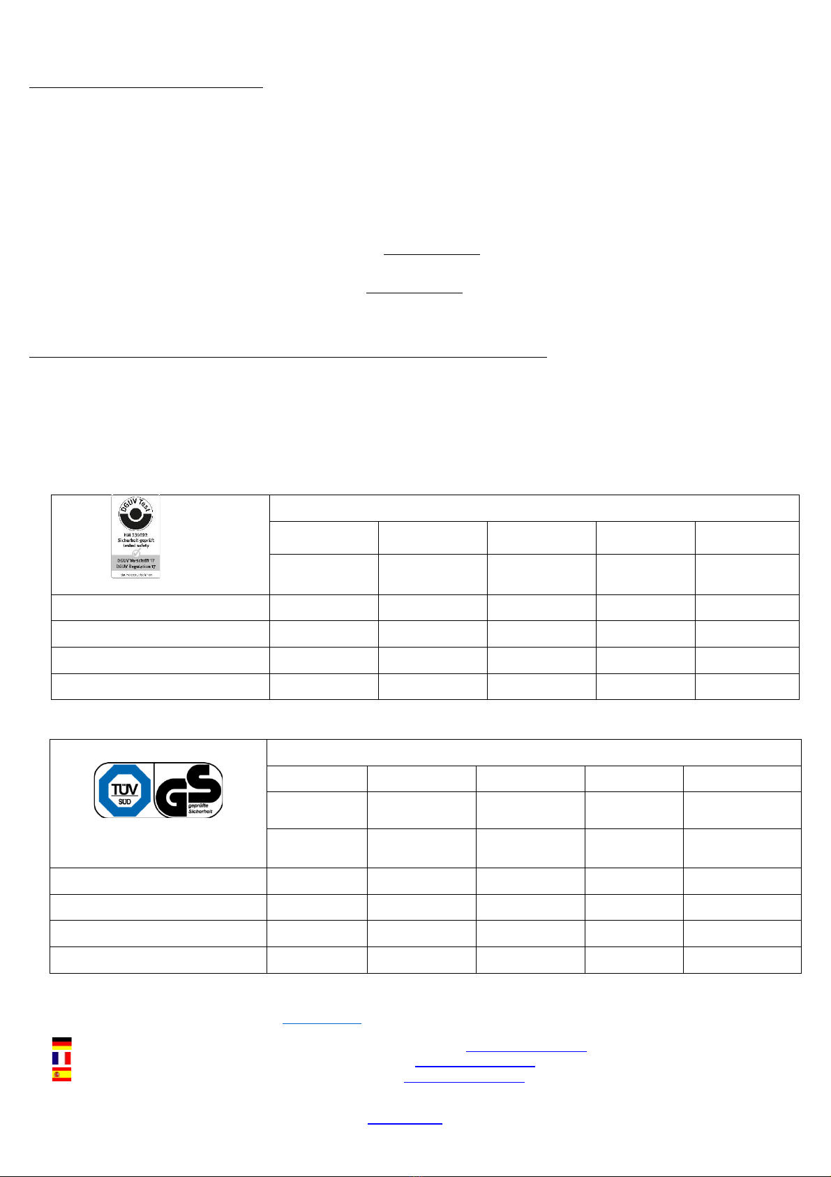
steel cables (wire ropes) - see table for details of maximum permissible loads (safe working loads / working load limit) and approved wire ropes.
Safe use of this suspension system requires sufficiently firm attachment/anchorage to a fastening point (ceiling, wall, floor, object) –the responsibility is / lies with the user.
Installation should always be made by qualified professionals.
Reutlinger GmbH reserves all legal rights to this instruction and operating manual, including, but not limited to, protection rights afforded under copyright and competition law. Any modification,
reproduction or distribution, in total or in parts and by any means, is only permitted with our written consent in prior. Any unauthorised use or transfer is expressly prohibited.
Attention:
All data displayed on the grip slider must be clearly visible and legible at all times (i.e. data is not permitted to be covered or over-stickered and it must not exhibit any signs of abrasion etc.). If
this requirement is not met, the approval under the German Accident Prevention Regulation “DGUV Vorschrift 17 (BGV C1)” will be forfeited and use of the grip slider will no longer be
permitted in this case.
In order to prevent any risk of confusion and to help clearly identify the applicable safe working load (working load limit) in each case of use, grip sliders with coupling threads must only be
connected to coupling parts that are not marked with a safe working load label of their own.
Only the safe working loads displayed on the grip slider and indicated in the table of this instruction and operating manual apply!
It is the user’s sole responsibility to ensure that the safe working load of any coupling parts used is NEVER lower than that of the grip slider and that all relevant regulations are adhered to at
all times.
Important: Please keep this instruction and operating manual within easy reach for future reference.
Safety Advice / Precautionary Statements:
1. Reutlinger grip slider are only approved for indoor use at temperatures between –20…+50°C.
2. Use of the grip sliders in swimming facilities (with a chloric atmosphere) or in any other corrosion-promoting environments (sea water areas or locations with high salt concentration in the
atmosphere) is not permitted.
3. Any dynamic forces acting, or likely to act, on the grip slider during assembly and disassembly must be taken into account for determining the actual maximum load on a case-by-case basis.
The indicated safe working load (working load limit/WLL) is the maximum load that should NEVER be exceeded! The grip sliders are not approved for performing dynamic/scenic movements
driven by stage machinery installations.
4. The casing of the grip slider must be impossible to open and must never be opened. Permanently fixed original parts should not removed.
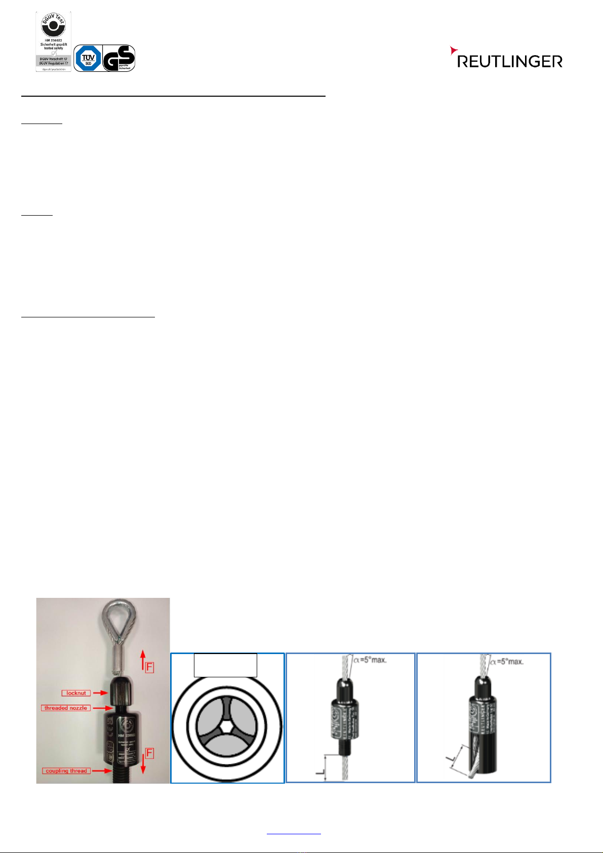
5. Before the cable holder is used, its nozzle (i.e. the threaded nose protruding from the cable holder’s top-end) must be able to be pushed inside with ease against the noticeable pressure of
the spring, and it should move out again by itself and return to its original position outside the grip slider when it is released.
6. The pass-through channel of the nozzle must be free of foreign particles so that proper functioning of the grip slider is ensured.
7. When looking through the nozzle, part of the circumference of six balls protruding into the nozzle’s pass-through channel must be visible (Fig.1). The lighter, central gap formed by the
configuration of the six balls is to form a hexagon in the pass-through channel, similar to a star with six points. If the six balls are not visible in the grip slider as described above, the grip slider
should not be used. Contact the Quality department of Reutlinger GmbH.
8. The surface of the wire rope to be threaded into the grip slider must be properly closed (i.e. sealed by tinning, welding, shrink-sleeving,…) so that an unravelling of the wire rope and thus
injury to the user from projecting wires or strands is prevented. If the wire rope needs to be shortened, its ends must be once again permanently sealed after the trimming is complete.
9. For safe operation and full load capacity (i.e. up to the working load limit) of the grip slider, the wire ropes must be entirely undamaged and free of dirt or other contamination.
10. Wire ropes and wires must not be pulled over edges (e.g. in case of models with side cable exit)!
11. The deflection angle of the wire rope from the vertical symmetry axis of the grip slider must not exceed α=5° (Fig.2, 2a).
12. The nozzle of the grip slider must under no circumstances be loaded (e.g. it must not be exposed to buckling or compressive stress etc.). It must remain accessible at all times.
13. The grip slider must be used in pairs as a minimum, i.e. the object to be suspended must be held by a minimum of two wire ropes in order to prevent rotation of the grip slider upon ist
own axis on the wire rope.
14. After overload, above the indicated safe working load (working load limit), grip slider should not be used again!
15. Wire ropes and grip slider should not be damaged ! „Critical Damage” includes (but is not limited to): Cracks, deformations and material loss such as may occur through impact, shock
or severe friction/abrasion. Slight abrasion or deformation of the nozzle may indicate presence of damage inside the grip slider caused by, for example, an impact on the nozzle (e.g. by
falling onto a hard surface). In case of any doubts or questions as to whether a particular Reutlinger grip slider exhibits uncritical traces of use or potentially critical damage, please contact
Reutlinger GmbH to be on the safe side.
16. Do NOT use any tools when mounting the grip slider onto its respective mating counterpart or when tightening the lock nut (safety nut).
Note: "There is no bound mounting direction!
Fig. 1 Fig. 2 Fig. 2a