REXROTH BODAS PR4280GB05/10 Installation instructions

RE 95156/02.2017, Bosch Rexroth AG
BODAS Pressure sensor
PR4
RE 95156
Edition: 02.2017
Replaces: 12.2015
Features
▶ Tightening torque 45 Nm
▶ Shock and vibration resistant
▶ High resistance to pressure spikes
▶ Very good resistance to temperature shock
▶ High accuracy over the complete measuring range
▶ Compact dimensions for all pressure ranges
▶ Thin-film measurement principle
▶ Measurement range
0 ... 280 bar
0 ... 420 bar and
0 ... 600 bar
▶ Ratiometric output signal 0.5 ... 4.5V
at 5V supply voltage
▶ Type of protection IP67 and IP69K
Inhalt
Ordering code 2
Description 2
Technical data 3
Characteristics 4
Dimensions 4
Connector Bosch Compact 5
Manufacturer confirmation of PR4 MTTFd-values 6
Installation instructions 7
Wiring and error diagnostic of the sensor 8
Error diagnosis 9
Safety instructions 11

Bosch Rexroth AG, RE 95156/02.2017
2PR4 | BODAS Pressure sensor
Ordering code
Ordering code
01 02 03 04 05 06
BODAS PR4 / 10
Type
01 Pressure sensor PR4
Measurement range
02 0 ... 280 bar 280
0 ... 420bar 420
0 ... 600bar 600
Mechanical connection 280 420 600
03 G1/4A according to DIN EN ISO 1179-2 ● ● – G
M14x1.5 according to ISO6149-2 – – ● M
Electrical connection
04 Bosch Compact B
Supply Output signal
05 5 ±0.25V 0.5 ... 4.5V ratiometric (at 5 V supply) 05
Series
06 10
●= Available –= Not available
Available variants
Type Material number
Bulk pack (136 pieces) Single pack
PR4 280 G B 05 / 10 R917C05562 R917A05562
PR4 420 G B 05 / 10 R917C09842 R917A09842
PR4 600 M B 05 / 10 R917C10105 R917A10105
Description
This sensor is used for measuring pressure in hydraulic
circuits. Due to its outstanding characteristics, it is also
ideally suited for use in mobile hydraulics: shock and
vibration resistance, type of protection, resistance
topressure spikes, resistance to temperature shock,
EMCcharacteristics better than 150 V/m. The measurement
principle uses a hermetically welded thin-film measurement
cell, which ensures long-term leak resistance. The sensor
signal can be directly evaluated by a BODAS controller RC.

RE 95156/02.2017, Bosch Rexroth AG
BODAS Pressure sensor | PR4
Technical data
3
Technical data
Type PR4 280
GB05
420
GB05
600
MB05
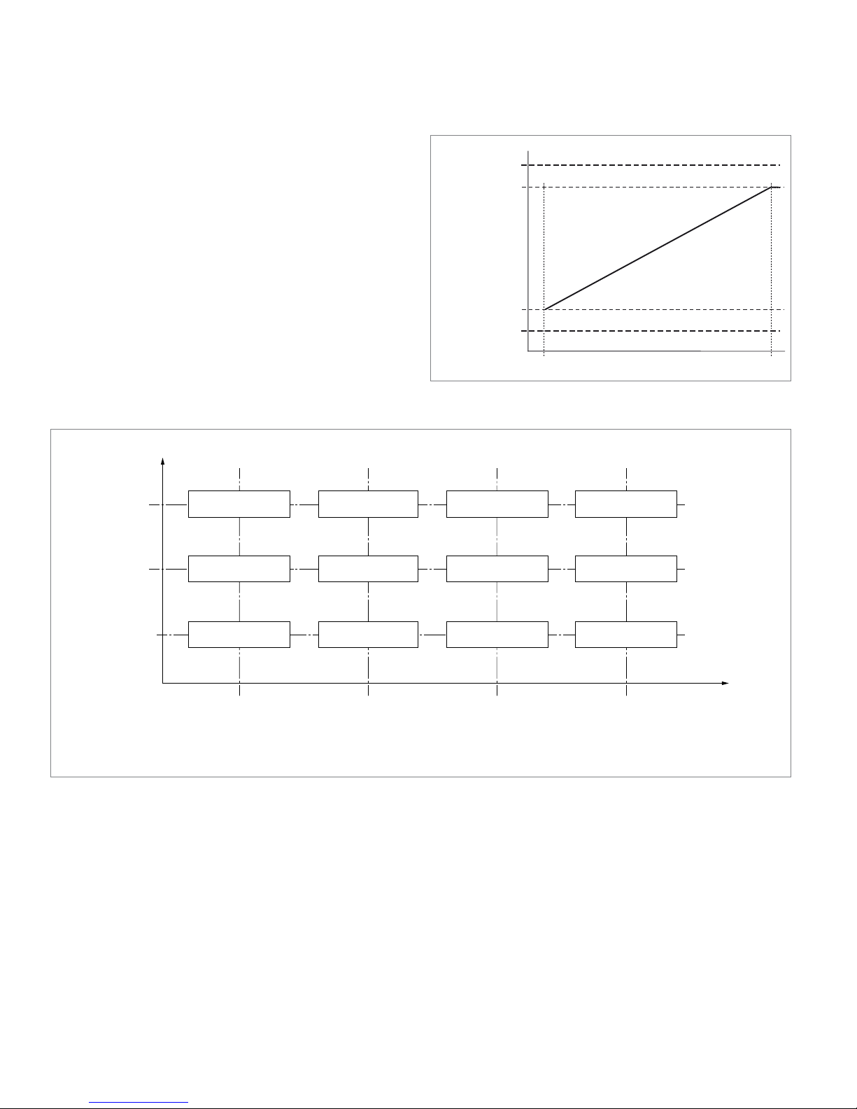
Measurement range 0 ... 280 bar 0 ... 420 bar 0 ... 600 bar
Overload limit1) 400 bar 560 bar 800 bar
Bursting pressure2)4) 2500 bar 3750 bar 5250 bar
Output signal 0.5V ... 4.5V, ratiometric (at 5 V supply)
Supply voltage Us5V ±0.25V
Maximum supply voltage 18V (maximum 1h)
Short circuit signal output to GND or supply voltage US,short = 0 … 18 V, (max. 8 h) in case of simultaneous supply of USwith US, short
Sensor output impedance Rdifferntial at
0.1Us<Uout<0.9Us
typical: 5 Ω
maximum: 10 Ω
Current consumption
Typical at 5V supply voltage 12 mA
Maximum without load ≤15mA
Maximum at reverse connection 260 mA
Connector Bosch Compact 1.1a
Parts contacting measuring materials X5CrNiCuNb16-4
Housing material PBT-GF30/CrNi steel
Response time (10 ... 90 %) ≤1.0 ms
Overall accuracy ≤1.5%, refer to table "tolerance over temperature, pressure and life time"
Medium temperature range3) –40 °C ... +140°C
Ambient temperature range –40°C ... +100°C
Storage temperature range –30°C ... +60°C at 0 ... 80% relative humidity and 5 years
Transportation conditions, Conditions deviating from the storage conditions are allowed for the transport:
Duration, max. 48 h temperature –40 °C ... +80 °C
Relative humidity 0 % ... 80 %
Service life 10000 operating hours or 15 years
Different values, depending on operational conditions on request
Pressure cycles over service life 10 million cycles
Shock resistance 50g (DIN EN 60068-2-27, 11ms), 500g (DIN EN 60068-2-27, 1ms)
Vibration resistance
Amplitude of the deflection s = 0.25 mm in the range 70 Hz ... 147 Hz
Amplitude of the acceleration a = 210 m/s2in the range 147 Hz ... 1350 Hz
a = 175 m/s2in the range 1350 Hz ... 2000 Hz
Frequency change 0.5 octave/min
Duration of excitation 100 h in each spatial direction with the same test specimen
Drop test
Controlled drop from 1 m height onto concrete in accordance with ISO 16750-3. One
drop event per axial direction. The component must then be fully functional or visually
damaged
CE conformity According to EMC directive 2014/30/EU (EN ISO 14982 and EN 13309)
E1 Type approval UN ECE 10 Rev4
Electromagnetic compatibility EMC ISO 11452-2, -4, -5 as well as according to IEC61000
BCI up ... 200 mA open and closed loop according ISO 11452-4 up ... 400 MHz.
Antenna > 150 V/m according ISO 11452-2 from 200 MHz - 3.2 GHz
Electrical protection Protection from voltage reversal, short circuits and undervoltage;
protection from overvoltage in the defined supply voltage range
Type of protection with installed mating connector IP67 and IPX9K according to ISO 20653 (2006-08-15)
Weight approx. G 1/4: 48g, M14: 52 g
1) maximum 15 minutes at Pnto Pmax
2) maximum 15 minutes at Pnto Pberst
3) 150°C: 250h over live time
4) The specifield bursting pressure is valid for the device only.
This value does not include the mechanical interface - the thread between the sen-
sor and the hydraulic component

Bosch Rexroth AG, RE 95156/02.2017
4PR4 | BODAS Pressure sensor
Dimensions and labeling
ø18.75±0.2
12.55±2
4±0.5
11±0.3
19.9±0.7
M14×1.56g
ø18.75±0.2
12±0.3
19.9±0.7
G1/4 A
Date of production and
serial number not encoded
Customer wordmark
ACC: ZN 02110-A7/2
Data matrix code
according typ ECC200
according ISO/IEC 16022
CE-marking
Nominal pressure
Materialnumber
R9170XXXXX
Sensor with mechanical connection M14 × 1.5
according DIN EN ISO 6149-2
Sensor with mechanical connection G 1/4
according DIN EN ISO 1179-2
Wrench size 27
Data matrix code content
Content Digits Count
Start digit 1 1
Customer content material number R917010105 2-11 10
Year of production 12-13 2
Day of the year 14-16 3
Serial number 17-21 5
Number of production-line 22 1
Content Digits Count
Bosch plant number 23-25 3
Last 4 digits from Bosch part-number 26-30 5
Bosch change index 31-32 2
Bosch drawing index 33-35 3
Empty place for CD-free sensor 36 1
Connector Bosch Compact
Pin assignment Assembly example
321
3
2
1
1 Ground GND
2 Output
3 Supply voltage Us
1 Compact 1.1a
2 End clip
3 Cap straight
Mating connector 1)
Mating connector sets with the following content are
available under Rexroth part number R917009890 for the
manual assembly of wiring harness connectors for laboratory
or small-series requirements:
Designation Number Material number
Bosch Compact 1.1a Connector 1 1928403966
BDK Terminal Gold for 18-20 AWG,
0.5-1.0 mm2
3 1928498054
Bosch compact cap straight 1 1928300527
Single seal, BDK, blue, ROHS 3 1928300599
End clip 1 1928403423
1) The mating connectors are not included in the scope of supply.
These are available from Bosch Rexroth under the corresponding
material numbers.

RE 95156/02.2017, Bosch Rexroth AG
BODAS Pressure sensor | PR4
Wiring and error diagnostic of the sensor
5
Instruction for cable guide
≥10
≥R50
≤150
– 45°
135°
Required tooling2)
Designation Number Material number
Bosch crimping tool
for BDK 2.8 terminal
0.5, 0.75, 1.0 sq mm wire
1 1928498161
Bosch terminal extraction tool
for BDK 2.8 terminals
1 1928498167
Notes regarding assembly
In the assembly of the connectors, respect the assembly
instructions for plug connections (Y 928 P00 222) and
BDK2.8 contacts (1 928 F00 025).
These assembly instructions are available on request from
Rexroth.
Caution:
In the installation of the connector in the vehicle, observe
the following:
The fixation of the cable harness must be done at a dis-
tance ≤ 150 mm after the outgoing cable unit at the same
vibration level of the sensor.
Electrical connection
▶ The device may only be installed by a trained electrician.
▶ The national and international specifications regarding
the installation of electro-technical systems must be
followed.
▶ Voltage supply according to SELV, PELV.
▶ De-energize the system.
Wiring and error diagnostic of the sensor
Recommended wiring of the sensor
The sensor is to be connected to the ECU according to the
following wiring diagram and provided with a supply volt-
age of 5 V.
▼ Sensor wiring in the ECU
Pin 3
Pin 2
Pin 1
Pressure sensor ECU
Signal
(UOUT)
+5 V (US)
A/D
converter
and μC
Pull up
resistance
GND
Supply voltage
Ground
The assignment of the connector pins of the high-pressure
sensor is depicted on previous page.
The pressure sensor delivers an analog output signal that
has a ratiometric relationship with the supply voltage.
Specification of the pull-up resistor:
Quantity Symbol Value Unit
min typ max
Pull-up resistor
as per US
RPull-up 4.41 4.64 4.87 kΩ
In addition to this, a low-pass filter with a time constant of
maximum 0.7 ms is to be provided in the signal path.
The electrical output of the sensor is designed such that
malfunctions through cable breaks or short-circuits can be
detected with the wiring shown in the representation with
a pull-up resistor of 4.64 kΩ ±5 % against supply voltage.
2) The tools may be purchased from Bosch dealers or Bosch Service
(www.bosch-service.com)
Drawings and further information about Bosch connectors and
tools can be found on the internet: www.bosch-connectors.com

Bosch Rexroth AG, RE 95156/02.2017
6PR4 | BODAS Pressure sensor
Error diagnosis
Error diagnosis
Diagnostic ranges outside the operating range are provided
for the error diagnosis (also see characteristic on page 8).
Since the sensor characteristic of the upper operating
range is limited, overpressure conditions can be distin-
guished from errors.
The coding of the response to an error in the following
table is as follows:
0 = no error band and no reset
-1 = lower error band and no reset
-2 = lower error band and reset is triggered
Response of the sensor in case of error
Error description Debounce characteristics Error mode
Initialization, P and T not yet available ‒1
Indicates that OTP Bit for final programming at Bosch of OTP Master is not set
(lock-bit not set)
error is set immediately,
no Reset is triggered
‒1
1) Power-on
complete RAM check (Read/Write)
beginning of continuous ROM check
2) Online
continuous ROM check
continuous RAM check
RAM/ROM checks DSP by Parity during each Access
HW-Check of SignalProcessor (Question/Answer)
signature monitoring of program counter
error is set immediately,
Reset is triggered
‒2
1) OTP CRC check of boot loading failed 4 times (consecutive)
2) Sum-check on trim data. Test carried out during boot loading and continuous cycle
1) error is set immediately,
Reset is triggered
2) error is set immediately,
Reset is triggered
‒2
Test on Aquisition Chain Pressure by injection of test signal before ADC on power-up
Thresholds are defined during EoL programming at Bosch for each sensor individually
error is set immediately,
Reset is triggered
‒2
Decimation interval error (Only possible in case of severe hardware malfunction) no Reset, debouncing next frame ‒1
Pressure Sensor element failure (Wiring Detection) ‒2
1) Power-On
Common Mode at Power-On
2) Online
Common Mode
Current Modulation
1) error is set immeadiately,
Reset is triggered
2) Reset, debouncing next frame
Signal Input ADC too high, also for Sensor Element Error no Reset, debouncing next frame ‒1
Signal Input ADC too low, also for Sensor Element Error no Reset, debouncing next frame ‒1
Reference temperature input too high or low no Reset ‒1
Failure of internal temperatur sensor --> HW Defects of ADC_T or PTAT itself no Reset ‒1
Low Voltage Supply detection, programmable threshold no Reset, debouncing next frame ‒1
High Voltage Supply detection, programmable threshold no Reset, debouncing next frame ‒1

RE 95156/02.2017, Bosch Rexroth AG
BODAS Pressure sensor | PR4
Error diagnosis
7
Behavior after reset and initialization
In case of certain errors, a reset is triggered in the sensor.
These are then generated every 400 ms. After a reset, and
during the subsequent initialization of the sensor, the
output is pulled to ground. If the error is still present, the
output signal remains in the lower error band. In case, the
error is no longer present, the output signal controls its
value into the applicable operating range. The course of
the output signal and the related typical time at room
temperature, after the reset, are shown in diagram below.
▼ Representation of the time after reset and initialization
V
0 t1 t2 t3 t
Reset
Operating range
Power-
up Lower
error band
Typicals [ms] t1 t2 t3
CRC OK 0.03 0.9 1.1
CRC NOK 0.03 2.1 2.3
Behavior after undervoltage and overvoltage
In case of undervoltage < 4.75 V or overvoltage > 5.25 V
detection, the output is pulled to ground.

Bosch Rexroth AG, RE 95156/02.2017
8PR4 | BODAS Pressure sensor
Characteristics
Characteristics
Output voltage as function of the pressure
The signal output voltage is (up to the nominal pressure)
calculated from the actual pressure as follows:
UOUT = (c1×p+c0)×US
where
UOUT = Signal output voltage
US= Supply voltage (typ. 5 V)
p= Pressure [MPa]
c0= 0.1
c1= 0.8 : pn
pn= Nominal pressure [MPa]
0pn
0.96 US(4.8 V)
0.90 US(4.5 V)
0.10 US(0.5 V)
0.04 US(0.2 V)
Upper range for signal range check (SRC)
Lower range for signal range check (SRC)
Values for
US= 5 V
in brackets
Pressure p
Tolerance over temperature, pressure and life time
0
new condition / after life time
pnenn
pnenn/2
Temperature
−40 °C
1.10
% / 1.50
%
0.90
% / 1.30
%
0.70
% / 1.10
%
−0 °C
0.70
% / 1.20
%
0.60
% / 1.10
%
0.50
% / 1.00
%
100 °C
0.70
% / 1.20
%
0.60
% / 1.10
%
0.50
% / 1.00
%
140 °C
1.10
% / 1.50
%
0.90
% / 1.30
%
0.70
% / 1.10
%
Pressure
The tolerance for the pressure measurement is given in
%FS= "full scale". FS denotes the sensor nominal pressure
pnenn or the usable range. The relative tolerance is depen-
dent on the pressure and temperature, and increases over
the service lifetime. Here, the service lifetime encompasses
the entire lifetime. The tolerances for new parts are statisti-
cally observed with 3s per manufacturing batch. Delivery of
100 % sorted products is permitted. After lifetime the toler-
ance for new parts can broaden to the values given in the
diagram. Here the given tolerances also represent the 3s
limit.

RE 95156/02.2017, Bosch Rexroth AG
BODAS Pressure sensor | PR4
Installation instructions
9
Installation instructions
Mounting
Mounting process of sensor must be ensured by customer
by adequate validation.
Rexroth recommends to wet the surface of thread and
tightening plane of pressure sensor completely with Oil or
Molykote WI5 prior to mounting.
To prevent accumulation of lubricant in the pressure port
application of lubricant by spraying while pressure port
facing downwards is recommended.
Recommended position α = ±0 ... 90° in all direction from
vertical position.
Tightening only permitted with hexagonal socket wrench or
with box wrench α >90°.
α
Vector of gravity
Mechanical connection
▶ Before installing and removing the device, make certain
that the system is not pressurized.
Tightening torque
Before mounting the PR4 pressure sensor, check the speci-
field tightening torque of the hydraulic pump, motor or valve
block.
If the torque for mounting the sensor in the respective
hydraulic component is not specifield use a torque of
35±5Nm.
Do not exceed the maximum tightening torque of: 45 Nm.
Operating conditions - temperatures
The sensor is designed for use in hydraulic components
(direct motor attachment) and the corresponding ambient
temperatures with a typical temperature distribution:
Temperature
‒40 °C 6 %
23 °C 20 %
85 °C 65 %
135 °C 8 %
140 °C 1 %
Storage conditions
The pressure sensor is to be stored under the following
conditions:
Temperature range ‒30 °C ... +60 °C
Rel. humidity 0 ... 80 % r. h.
Maximum storage duration after the delivery
by the Bosch production plant
5 years
The sensor has to be kept under dry and dust-free storage
conditions. It is important to ensure that there is no con-
tamination due to liquid or solid media in the connector
area or on the threaded fitting. Sulfurous atmospheres have
to be avoided for silver-plated connector pins.
These storage conditions do not lead to any change in the
properties and the functioning of the high-pressure sensor.
After the maximum storage duration is exceeded, the sen-
sors must be sent back to Bosch Rexroth AG for inspection
or testing.
Transportation conditions
Conditions deviating from the storage conditions are
allowed for the transport:
Duration max. 48 h
Temperature ‒40 °C ... +80 °C
Relative humidity 0 % ... 80 %

Bosch Rexroth AG, RE 95156/02.2017
10 PR4 | BODAS Pressure sensor
Manufacturer confirmation of PR4 MTTFd-values
The MTTFd-values were determined in accordance with ISO 13849-1:2008-12, Appendix D, Parts Count Method, and the
specified temperature profiles below.
Ambient temperature
Control unit [°C]
Self-heating
[°C]
Temperature profile, Operating time share [%]
1234567
10 10 100 0 0 0 0 0 0
20 10 0 100 0 0 0 0 0
30 10 0 0 100 0 0 0 0
40 10 0 0 0 100 0 0 0
50 10 0 0 0 0 100 0 0
60 10 0 0 0 0 0 100 0
70 10 0 0 0 0 0 0 100
80 10 0000000
90 10 0000000
100 10 0 0 0 0 0 0 0
110 10 0 0 0 0 0 0 0
120 10 0 0 0 0 0 0 0
130 10 0 0 0 0 0 0 0
140 10 0 0 0 0 0 0 0
MTTFd-value [years] with 4h use per day 594 592 589 585 578 569 556
8h use per day 371 370 368 365 361 356 347
16h use per day 212 212 211 209 207 203 199
24h use per day 149 148 147 146 145 142 139
MTTFd-value of the printed circuit board 15712 11362 8117 5738 4010 2767 1881
Ambient temperature
Control unit [°C]
Self-heating
[°C]
Temperature profile, Operating time share [%]
8 9 10 11 12 13 14 15
-40 10 00000006
10 10 00000000
20 10 00000000
23 10 000000020
30 10 00000000
40 10 00000000
50 10 00000000
60 10 00000000
70 10 00000000
80 10 100 0 0 0 0 0 0 0
85 10 000000065
90 10 0 100 0 0 0 0 0 0
100 10 0 0 100 0 0 0 0 0
110 10 0 0 0 100 0 0 0 0
120 10 0 0 0 0 100 0 0 0
130 10 0 0 0 0 0 100 0 0
135 10 00000008
140 10 0 0 0 0 0 0 100 1
MTTFd-value [years] with 4h use per day 536 508 468 416 351 280 209 486
8h use per day 335 317 293 260 220 175 131 304
16h use per day 192 182 167 149 126 100 75 174
24h use per day 134 127 117 104 88 70 52 122
MTTFd-value of the printed circuit board 1258 826 534 339 212 131 80 641

RE 95156/02.2017, Bosch Rexroth AG
BODAS Pressure sensor | PR4
Safety instructions
11PR4 | BODAS Pressure sensor
Safety instructions
General instructions
▶ Before finalizing your design, request a binding installation
drawing.
▶ The proposed circuits do not imply any technical liability
for the system on the part of Bosch Rexroth.
▶ It is not permissible to open the sensor or to modify or
repair the sensor. Modifications or repairs to the wiring
could result in dangerous malfunctions.
▶ Only allow pressure measurement devices to be
installed by trained and specialist personnel who are
authorized by the system owner.
▶ Connections must only be opened while in a
depressurized state!
▶ System developments, installation and commissioning of
electronic systems for controlling hydraulic drives must
only be carried out by trained and experienced
specialists who are sufficiently familiar with both the
components used and with the complete system.
▶ While commissioning the sensor, the machine may pose
unforeseen dangers. Before commissioning the system,
you must therefore ensure that the vehicle and the
hydraulic system are in a safe condition.
▶ Make sure that nobody is in the machine’s danger zone.
▶ No defective or incorrectly functioning components may
be used. If the sensor should fail or demonstrate faulty
operation, it must be replaced.
▶ Residual measurement materials in unmounted pressure
measurement devices could endanger people, the
environment and equipment. Take appropriate
precautionary measures.
▶ In spite of taking great care in preparing this document,
all conceivable application cases could not be taken into
account. If information is lacking for your specific
application, please contact Bosch Rexroth.
Notes on the installation location and position
▶ Do not install the sensor close to parts that generate
considerable heat (e.g. exhaust).
▶ Wires are to be routed with sufficient distance from hot
or moving vehicle parts.
▶ A sufficiently large distance to radio systems must be
maintained.
▶ The connector of the
sensor
is to be unplugged during
electrical welding and painting operations.
▶ Electrostatic painting of the sensor is not allowed
(hazard: ESD damage).
▶ Cables/wires must be sealed individually to prevent
water from entering the device.
▶ Make sure, by appropriate installation of the sensor, that
no water is gathering the sensor measuring element.
This might result to a malfunction of the measuring
signal (freezing condition, in worst case: crack of
measuring element).
Notes on transport and storage
▶ Please inspect the device for any damages which may
have occurred during transport. If there are obvious
signs of damage, please immediately inform the trans-
port company and Bosch Rexroth.
▶ If it is dropped, the
sensor
must not be used any longer
as invisible damage could have a negative impact on
reliability.
Notes on wiring and circuitry
▶ Use twisted pair wires to connect the pressure sensor.
▶ Use short wires to avoid voltage drop along the lines
and choose wires with bigger gauge in case of longer
distances between the sensor and the electronic.
▶ We recommend to use shielded wire to increase the
signal quality. Connect the shield on one side, either to
the machine or the vehicle ground or to the electronic
via a short low resistance connection.
▶ The mating connector of the sensor must not be plugged
or unplugged, if the electrical system of the machine is
energized.
▶ The sensor wires are sensitive to radiation interference.
For this reason, the following measures should be taken
when operating the sensor:
– Sensor wires should be attached as far away as
possible from large electric machines.
– If the signal requirements are satisfied, it is possible
to extend the sensor cable.
▶ Wires from the
sensor
to the electronics must not be
routed close to other power-conducting lines in the
machine or vehicle.
▶ The wiring harness should be fixated mechanically in the
area in which the sensor is installed (spacing < 150mm).
The wiring harness should be fixated so that in-phase
excitation with the sensor occurs (e.g. at the sensor
mounting points).
▶ If possible, wires should be routed in the vehicle
interior. If the wires are routed outside the vehicle, make
sure that they are securely fixed.

12
Bosch Rexroth AG, RE 95156/02.2017
Bosch Rexroth AG
Mobile Applications
Robert-Bosch-Straße 2
71701 Schwieberdingen, Germany
Tel. +49 93 52 40 50 60
info.bodas@boschrexroth.de
www.boschrexroth.com
©BoschRexrothAG2017. All rights reserved, also regarding any disposal,
exploitation, reproduction, editing, distribution, as well as in the event of
applications for industrial property rights. The data specified within only
serves to describe the product. No statements concerning a certain condi-
tion or suitability for a certain application can be derived from our informa-
tion. The information given does not release the user from the obligation of
own judgment and verification. It must be remembered that our products are
subject to a natural process of wear and aging.
PR4 | BODAS Pressure sensor
Safety instructions
BODAS Pressure sensor | PR4
▶ Wires must not rub against edges and must not be
routed through sharp-edged ducts without protection.
▶ Bosch Rexroth warranty will cover the function of the
connector system only in the case of combination with
harness connector system parts according to this data
sheet.
▶ Use only the appropriate tooling to crimp and mount the
mating connector.
Attention:
Use harness connector for protection against water
ingress.
▶ First cable mounting point max. 150 mm after the plug
(straight cable length). It must be located on the sensor
carrier.
▶ Angle of bending the cable (deviation from straight line)
between cable exit at sensor and first mounting point,
20° ... 90°.
▶ Admissible bending radius of the cable up to the first
cable mouting point: R≥ 50 mm.
▶ Installation instructions see also corresponding offer
drawing.
Intended use
▶ The
sensor
is designed for use in mobile working
machines provided no limitations/restrictions are made
to certain application areas in this data sheet.
▶ Prior to installation, commissioning and operation, make
certain that the correct pressure measurement device
was selected with respect to measurement range,
design and – based on the specific measurement condi-
tions – parts which are in contact with measuring mate-
rials (corrosion). Furthermore, the respective national
safety regulations are to be observed.
▶ Operation of the
sensor
must generally occur within the
operating ranges specified and released in this data
sheet, particularly with regard to voltage, temperature,
vibration, shock and other described environmental
influences.
▶ If required, install a throttle, that limit possible pressure
peaks. Attention should be also paid to side effects e.g.
cavitation. Ensure that there will be no cavitation in any
point of operation.
▶ Use outside of the specified and released boundary
conditions may result in danger to life and/or cause
damage to components which could result in conse-
quential damage to the mobile working machine.
▶ Failure to observe the respective specifications may
result in serious bodily injury and/or property damage.
Improper use
▶ Any use of the
sensor
other than that described in chap-
ter “Intended use” is considered to be improper.
▶ Use in explosive areas is not permissible.
▶ Damages which result from improper use and/or from
unauthorized, interference in the component not
described in this data sheet render all warranty and
liability claims with respect to the manufacturer void.
Use in safety-related functions
▶ The customer is responsible for performing a risk analy-
sis of the mobile working machine and determining the
possible safety-related functions.
▶ In safety-related applications, the customer is respon-
sible for taking suitable measures for ensuring safety
(sensor redundancy, plausibility check, emergency
switch, etc.).
▶ Product data that is necessary to assess the safety of
the machine can be provided on request or are listed in
this data sheet.
Further information
▶ Further information about the
sensor
can be found at
www.boschrexroth.com/mobile-electronics.
▶ The sensor must be disposed according the national
regulations of your country.
This manual suits for next models
2
Table of contents
Other REXROTH Accessories manuals
Popular Accessories manuals by other brands

Haushalt International
Haushalt International 60250 Assembly instructions and user's manual

Point Six
Point Six WOWTHL Installation and operation instructions

Homematic IP
Homematic IP HmIP-PS-2 operating manual

paramondo
paramondo Pergorama 4000 installation instructions

3B Medical
3B Medical LM4000 user manual

Palram
Palram Aquila 1500 manual