REYMSA COOLING TOWERS, INC.
www.reymsa.com
The
All-Fiberglass
Cooling Towers
Index
Table A-5: Flanges recommended torque 15
Table B-1: Operation and Start-up basin level 32
Table C-1: Maximum operating temperatures 39
Table C-2: Maximum operating pressure 39
Table C-3: Water chemistry guidelines 40
Table C-4: Cycle of concentration 42
Table C-5: Recommended solution freezing protection temperature 44
Table D-1: Recommended Tower and optional equipment maintenance schedule 47
Table D-2: Oil capacity for gear reducer models 52
Table D-3: Copper coil unit(s) weight by model 55
FIGURES
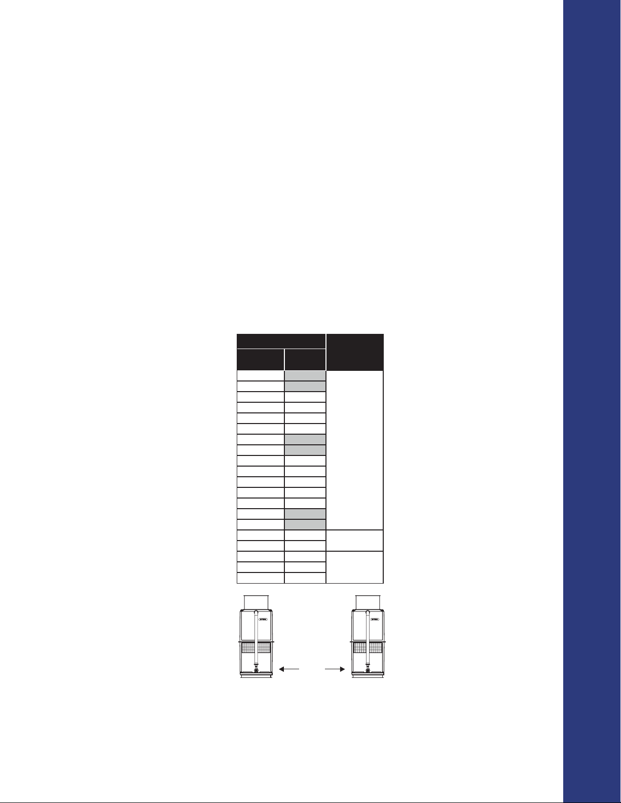
Figure A-1 : Minimum recommended distance between towers 1
Figure A-2: Recirculation 2
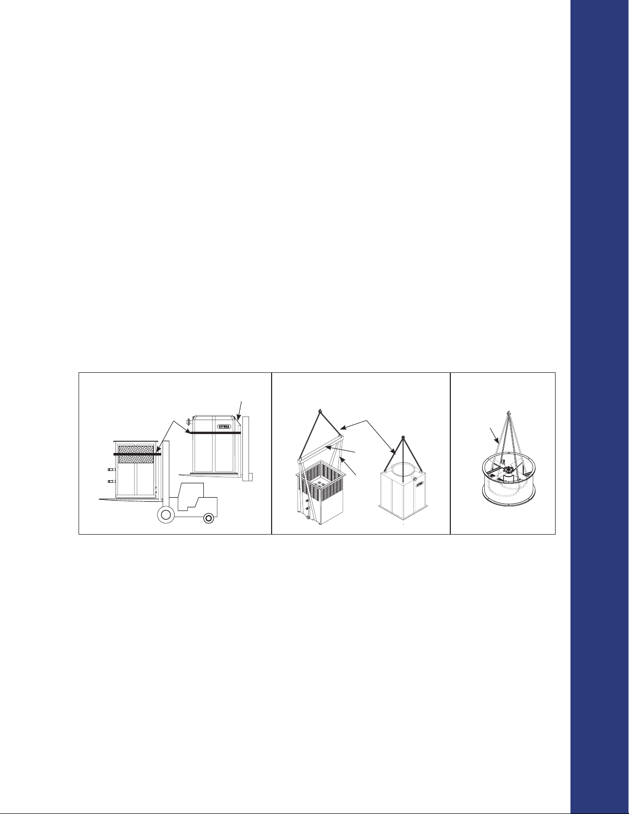
Figure A-3: Single Fan Tower Fork lifting 3
Figure A-4: Single Fan Tower Crane Lifting 3
Figure A-5: Fan Duct Lifting 3
Figure A-6: Typical anchorage for a single fan tower 4
Figure A-7: Upper and lower parts installation 4
Figure A-8: Fan duct assembly for a single tower 5
Figure A-9: Fan duct alignment for a single tower 5
Figure A-10: Double fan tower fork lifting 6
Figure A-11: Double fan tower crane lifting 6
Figure A-12: Fan Duct Lifting 6
Figure A-13: Basin lifting (optional) 7
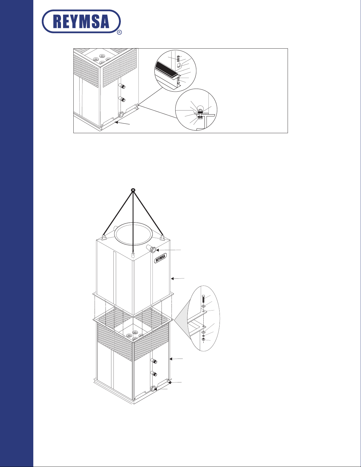
Figure A-14: Typical anchorage for a double fan tower 7
Figure A-15: Fan duct, upper and lower parts installation 7
Figure A-16: Fan duct assembly for a double fan tower 8
Figure A-17: Fan duct alignment for a double fan tower 8
Figure A-18: Double fan tower fork lifting 9
Figure A-19: Double fan tower crane lifting 9
Figure A-20: Fan duct lifting 9
Figure A-21: Basin lifting (optional) 10
Figure A-22: Typical anchorage for a quadruple fan tower 10
Figure A-23: Lower section installation for quadruple fan tower 10
Figure A-24: Upper section 1 quadruple fan tower 10
Figure A-25: Upper section 1 & 2 for a quadruple fan tower on plane 11
Figure A-26: Fan duct installation for a quadruple fan tower 12
Figure A-27: Fan duct alignment for a quadruple fan tower 12
Figure A-28: Lifting for HFC-F models 13
Figure A-29: Typical anchorage for HFC-F models 13
Figure A-30: Upper body section installation for HFC-F models 14
Figure A-31: Fan duct assembly for HFC-F models 14
Figure A-32: Screen mesh assembly for HFC-F models 14
Figure A-33: Spray pump and water return pipes assembly to tower 15
Figure A-34: Copper coil unit 16
Figure A-35: Fan adaptor in a single fan tower 17
Figure A-36: Fan adaptor installation 17
Figure A-37: Fan adaptor alignment 17
Figure A-38: Fan adaptor 2 installation 18
Figure A-39: Fan duct installation on a fan adaptor 18
Figure A-40: Fan duct alignment 18
Figure A-41: Fan duct installation in a fan adaptor for a quadruple fan tower 18
Figure A-42: Optional accessories by REYMSA 19
Figure A-43: Optional safety accessories 20
Figure A-44: Vibration switch recommended location 21
Figure A-45: Internal switches 21
Figure A-46: Typical electric diagram 21
Figure A-47: Vibration switch detail 22
Figure A-48: Sensitivity adjustment 22
Figure A-49: Basin heater system 23
Figure A-50: Recommended basin heater mounting 23
Figure A-51: Basin heater control panel diagram 24
Figure A-52: Electrical water level control system 25
Figure A-53: Electrical Connections & Water Level Control Parts 25
Figure A-54: Motor Shaft Grounding Ring 26
Figure A-55: Motor Shaft Grounding Ring Path to Ground 26
Figure A-56: Example of a base support 27