Rez Ranger 80 User manual

User Manual
RezAntenna.com | support@RezAntenna.com
RANGER 80
™
Re
|antenna systems|
™

IMPORTANT!
WARNING: ELECTRICAL SHOCK HAZARD
DO NOT USE NEAR POWER LINES. CONTACT WITH POWER LINES CAN
CAUSE AN ELECTRICAL SHOCK. SERIOUS INJURY OR DEATH MAY
OCCUR.
WARNING: IMPALEMENT HAZARD
THE MOUNTING SPIKE HAS A SHARP TIP AND IS CAPABLE OF
IMPALING A HUMAN BODY. THIS CAN CAUSE SERIOUS INJURY OR
DEATH. ALWAYS USE EXTREME CAUTION WHEN HANDLING.
WARNING: TIPPING HAZARD
KEEP A WIDE RADIUS AROUND THE ANTENNA CLEAR OF PEOPLE AND
OBJECTS. IF THE ANTENNA IS IMPROPERLY DEPLOYED OR IS USED
IN WINDY CONDITIONS IT CAN TIP OVER. THIS CAN CAUSE SEVERE
INJURY, AND OR PROPERTY DAMAGE.
WARNING: FIRE HAZARD
DO NOT EXCEED THE POWER LIMITS LISTED IN THE SPECIFICATIONS
SECTION OF THIS MANUAL. EXCEEDING THE POWER LIMITS CAN
RESULT IN A FIRE. EXCEEDING THE POWER LIMITS WILL VOID YOUR
WARRANTY.
MANUAL VERSION 1.1

REZ Antenna Systems™ Ranger 80™
Specifications
Kit Contents:
(1) Ranger 80 Loading Coil Base
(1) 9.8’ Military Whip
(1) [Z]QD-RP Radial Puck
(4) 33’ 18ga Radials
(1) Mounting Spike
(1) Backpack
Thank you for purchasing your REZ Antenna Systems Ranger 80! This manual will familiarize you with how to set up,
tune, and perform basic maintenance on your antenna. We take great pride in the build quality of our products, but should
you have any issues or questions, please email us at support@rezantenna.com.
We hope you enjoy your new antenna for many years to come!
COIL BASE
Length 21”
Max Dia. 2.25”
Material Delrin & 6061 Aluminum
Hardware Stainless Steel
Coax Connector SO-239
Power Limits 200 Watts SSB, 100 Watts Digtal (50%
Duty Cycle)
MOUNTING SPIKE
Length 17”
Spike Dia. 3/8”
Max Dia. 1”
Material 316 Stainless Steel
Thread Pitch 3/8-24
RADIAL SYSTEM
Wire Length 33’ (Set of 4)
Wire 18ga Stranded Copper
Termination 4mm Banana Plug
Radial Puck 3/8-24 Thread Pitch, (8) 4mm Banana
Jacks
HEAVY DUTY MILITARY WHIP
Length 9.3’
Material Stainless Steel/Brass
Finish Black
Mounting Thread 3/8-24 Thread Pitch
1

Set Up
1. Find a suitable location to deploy the antenna. Stay far away from any potential hazards and at least 15 feet from
any metal structures. They can detune the antenna and cause issues with tuning.
2. Drive the ground spike into the ground using a rubber mallet. Do not use any hard objects such as rocks or a metal
hammer. This will cause damage to the spike. NEVER attempt to drive the spike in with the coil base attached, this
will cause undue wear and void your warranty. Note: the spike is intended for deployment in soft soils. If you plan to
operate in rocky/hard soil consider purchasing the [Z]Pod tripod.
3. Thread the Ranger 80 coil base into the ground spike (or [Z] Pod)
4. Assemble the collapsible military whip beginning at the top and working your way towards the bottom. Starting at
the top makes the whip easier to assemble.
5. Thread the whip into the top of the coil base.
6. To deploy each radial, hold the banana plug end in one hand and throw the coil of wire in the direction you want
to deploy each radial with the other. Note: For this to work properly it’s important to follow the radial coiling
instruction video.
7. Insert the banana plug into the radial puck. A symmetrical pattern works best but is not necessary. Note: there are
eight jacks on the puck allowing for expansion of radials at a later date. Make your own or purchase an additional [Z]
QD-RK Radial kit.
8. Proceed to tuning.
1 2 3
4 5 6
7 8
SCAN TO VIEW
SETUP VIDEO
2

Analyzer Method
Tuning
With the included whip, the Ranger 80 is capable of tuning from 3.5 MHz to 29.7 MHz with an SWR of less than 2:1. The
Ranger 80 is also capable of higher frequenices when paired with a telescopic whip such as our Light Duty Telescopic
whip. Use one of the following methods to get the antenna tuned:
Note: Dierent soils, radial configurations, and mounting options will aect the ground system of the Ranger 80. Depending on these factors, you may notice a dierence
in the SWR and resonant point of the system. This is normal and well documented behavior of any vertical antenna system. For further information we reccomend reading
Rudy Severns’ (N6LF) work on radial ground systems here: antennasbyn6lf.com/2009/12/series-of-qex-articles-on-ground-system-experiments.html
For the best performance we recommend using this method. This is the most accurate way to achieve the lowest
possible SWR on this antenna system. Once you’re familiar with the process changing bands should take less than a
minute.
1. Connect your coax to the coil base and analyzer.
2. Slide the tuning collar to the “ballpark” area of the band you wish to use. The higher the collar is the higher the resonant point.
(SEE FIG. 1)
3. Stand at least 10 feet from the antenna and run a sweep. If you stand too close, your body will detune the antenna and throw o
your measurements.
4. Note where the resonant frequency is and move the tuning collar the corresponding direction a few clicks at a time. Step away
each time and view the results on your analyzer. (SEE FIG. 2)
5. As you get closer to your target start moving the tuning collar one click at a time.
6. Once you’ve overshot your MHz target by one click take the tuning collar back one click and begin fine tuning.
7. To fine tune, spin the tuning collar either clockwise or counterclockwise. This will cause the tuning collar contact to follow the
groove between each wire like a screw.
8. Looking from the top of the coil, a clockwise turn will lower the resonant frequency and counterclockwise will increase the
resonant frequency. (SEE FIG. 3)
9. Slowly spin the tuning collar a small amount in the required direction and step away each time until the resonant point aligns
with your desired frequency. (SEE FIG. 4)
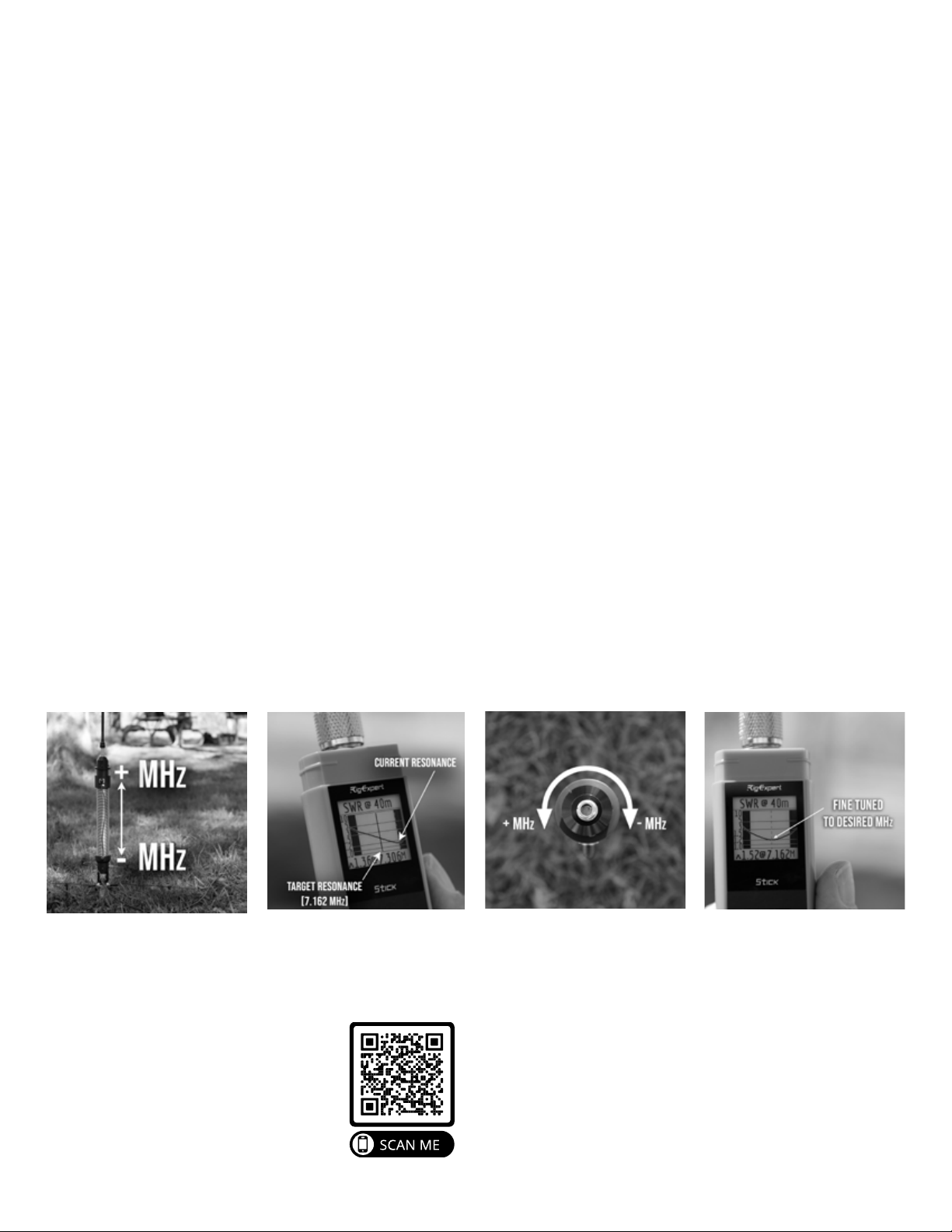
FIG. 2 - Since the target resonance is lower
than the current resonance, the tuning
collar must be moved down.
FIG. 3 - Spinning the tuning collar clockwise
lowers the resonant point. Spinning the
tuning collar counterclockwise inscreases
the resonant point.
FIG. 4 - After turning the tuning collar the
appropriate direction, the resonant point
directly aligns with the desired frequency.
FIG. 1 - Lowering the tuning collar results
in a lower MHz resonant point, raising it
increases the MHz.
SCAN TO VIEW
TUNING VIDEO
3

Noise Method
1. Connect your coax to your radio and to the coil base.
2. Find an empty frequency so all you hear is noise. Turn o noise reduction if your radio has it.
3. Turn the radio up loud enough to hear the noise from where you’ve deployed the antenna.
4. Slide the tuning collar to the “ballpark” area of the band you wish to use. The higher the collar is the higher the
resonant point.
5. You should hear the noise begin to get louder and louder as you tune the antenna closer to your desired frequency.
6. Keep moving the collar a few clicks at a time, stepping away each time, until you get the loudest noise possible. If you
hear the noise peak and get softer, then you’ve passed the resonant point. Back the tuning collar up until the noise is
loudest again. Begin fine tuning if desired.
7. You may be able to fine tune using the noise in some instances. Use the same process as the analyzer method but
instead, listen for the peak in the noise. You may not be able to detect any perceivable dierence in noise at this point
and that’s okay, this is not an exact tune.
8. Check your SWR at your radio to make sure you are within range of what your radio can tolerate.
9. Begin operating!
This method requires finding an empty frequency on your radio and using the noise floor to tune the antenna. This
method will get you close enough to operate in a pinch but is not recommended unless you have a tuner to clean up the
remaining mismatch.
4

General Maintenance
The Ranger 80 requires very little maintenance, but following a few basic procedures will keep your antenna operating
at peak performance.
1. When operating in harsh environments, wipe down the coil unit with a damp cloth followed by a dry microfiber
cloth.
2. Clean dirt from mounting spike using damp cloth.
3. Clean any dirt/debris from the mounting threads.
Every Several Uses:
1. Ensure all screws and bolts are tight.
2. Coat each ferrule connection on the whip with a thin coat of dielectric grease. This helps keep moisture out of the
whip.
After Each Use:
Warranty Information
Each product is covered by a 1 year limited warranty.
REZ ANTENNA SYSTEMS LLC, warranties this product to be free from defects in material or workmanship for a
period of one (1) year following the date of purchase, provided that the product is used for amateur radio purposes.
This limited warranty does not cover failures due to abuse, accidental damage or when repairs have been made
or attempted by anyone other than REZ ANTENNA SYSTEMS LLC. A defective product meeting the warranty
conditions set forth herein will be replaced or repaired at no charge in the following manner:
Send the product (prepaid) to the REZ ANTENNA SYSTEMS LLC Service Center for repair or replacement at
REZ ANTENNA SYSTEMS LLC’s option. Proof of purchase may be required. Information about REZ ANTENNA
SYSTEMS LLC’s service center and warranty instructions can be found at www.rezantenna.com/warranty.
This warranty gives you specific legal rights and you may have other rights which vary from state to state. Should you
have any questions, contact the REZ ANTENNA SYSTEMS LLC Service Center. This product is not intended for
commercial use, and accordingly, such commercial use of this product will void this warranty. All other guarantees,
express or implied, are hereby disclaimed.
5
Table of contents