RF Logic RF257 User manual

Page 1
RF Logic Limited.
Unit 18, The Enterprise Centre,
Coxbridge Business Park, FARNHAM,
Surrey GU10 5EH
Tel +44 (0)1252 268340
web: www.rflogic.co.uk
Electronic Product Design
Automatic Modulation Meter
Model RF257
Service Manual
Model RF257 Automatic Modulation Meter
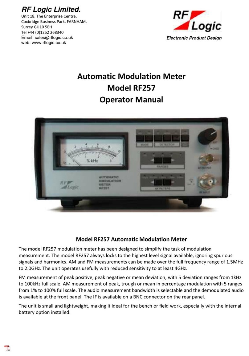
The model RF257 modulation meter has been designed to simplify the task of modulation
measurement. The model RF257 always locks to the highest level signal available, ignoring
spurious signals and harmonics. AM and FM measurements can be made over the full
frequency range of 1.5MHz to 2.0GHz. The unit operates usefully with reduced sensitivity to
at least 4GHz.
FM measurement of peak positive, peak negative or mean deviation, with 5 deviation
ranges from 1kHz to 100kHz full scale. AM measurement of peak, trough or mean in
percentage modulation with 5 ranges from 1% to 100% full scale. The audio measurement
bandwidth is selectable and the demodulated audio is available at the front panel. The IF is
available on a BNC connector on the rear panel.
The unit is small and lightweight, making it ideal for the bench or field work, especially with
the internal battery option installed.

Page 2
Contents
Operating Instructions 4
Power Requirements. 4
AC MAINS OPERATION 4
Input Signal. 4
FM Measurement. 5
AM Measurement. 5
Internal Battery Operation (Option 03). 5
Demodulated Audio Output. 5
IF Output. 5
RF257 Specification 6
RF Input 6
FM Measurement 6
AM Measurement 6
Audio Filters 7
Front Panel 7
Rear Panel 7
Power Requirements 7
Environmental 7
Temperature 7
Mechanical 7
Internal Battery (Option -03) 8
Technical Description 8
Introduction 8
System Description. 8
RF System. 8
AM Demodulation. 8
FM Demodulation. 8
Frequency Locking System 8
Lock Indication 9
AF System 9
Circuit Description. 9
RF Circuit 9
AF Circuit 10
Control Lines 12
Calibration 13
Test Equipment Required 13
AF Board Test 13
PSU Test 13
Front Panel Interface Tests 13
Set Potentiometers on AF Board 13
FM 60kHz Bandpass 14
FM 15kHz Bandpass 14

Page 3
FM 3.5kHz Bandpass 14
AM 60kHz Bandpass 14
AM 15kHz Bandpass 14
FM 3.5kHz Bandpass 15
Psophometric Filter 15
De-Emphasis 15
RF Board Test 16
Discriminator 16
Lock LED 16
AM Demodulator 16
Tuned Circuit Adjustments 16
AM Calibration 17
FM Calibration 17
Bessel Zero Method 17
Frequency Difference Method 17
Additional Checks 18
Battery Tests (Option 03) 18
Battery Monitor 18
Parts Lists 19
RF257-03 Complete Unit 19
900.308 Chassis Module 19
900.310 Front Panel Module 19
900.132 Front Panel PCB Assembly 20
900.303 AF Board Assembly 20
RF115v03 RF Board Assembly 23
Circuit Diagrams 27
AF Board Circuit 1 of 3 27
AF Board Circuit 2 of 3 28
AF Board Circuit 3 of 3 29
RF Board Circuit 1 of 4 30
RF Board Circuit 2 of 4 31
RF Board Circuit 3 of 4 32
RF Board Circuit 4 of 4 33
Front Panel Board Circuit 34
PCB Legends 35
AF Board Legend 35
RF Board Legend 36
Front Panel Board Legend 37

Page 4
Operating Instructions
Power Requirements.
AC MAINS OPERATION
WARNING
INCORRECT SUPPLY RANGE SELECTION COULD
CAUSE SERIOUS DAMAGE TO THE INSTRUMENT
Two AC power ranges are available, 102V - 130V and 205V - 260V. Make sure any mains
connection is removed from the unit. Remove the four bottom case screws and remove
cover. Select the appropriate range on the mains selector switch. This is located adjacent to
the mains transformer on the bottom PCB inside the instrument and is identified as W1.
Replace bottom cove and screws.
Connect the power lead to the local AC supply socket. The instrument is switched on by
switching the front panel rotary switch to 'ON'. The instrument is immediately ready for
use; no warm-up time is required. At power on, the RF257 defaults to the FM 100kHz range
with the mean detector and the 3.5kHz filter selected.
Input Signal.
Connect the signal source to the 'INPUT' socket, the 'LOCK' LED should immediately
illuminate if the signal is within the range 2mV to 1V. The 'LOCK' LED shows that the
instrument is correctly tuned to the incoming signal. The measuring circuits are inhibited
when the 'LOCK' indicator is not lit. DO NOT APPLY MORE THAN 1V (2.8V p-p), the input
circuitry will be damaged.
The instrument locks to the highest level signal applied to the input. It will not lock to a
harmonic or other spurious signal provided that the intended carrier has the highest level
signal and that it is within the specified frequency range. The tuning mechanism provides a
continuous dynamic frequency lock that permits accurate modulation measurements to be
taken even on a slowly sweeping carrier.
In general, the instrument provides good selectivity against interference from spurious
signals. However, the broadband nature of the input circuit implies that the possibility of
such interference cannot be completely eliminated. If it is suspected that a reading is being
affected by high level interfering signals, make a check by disconnecting and reconnecting
the signal source several times; any change in the modulation reading implies interference.
Normal harmonic levels, even in the worst case, are unlikely to have any effect on
measurements.

Page 5
FM Measurement.
Select the FM mode with the 'MODE FM' pushbutton.
Select the appropriate 'RANGE' with the < > pushbuttons. Five ranges are available with full
scale deviations of 1, 3, 10, 30 and 100kHz.
Select the required 'AF FILTER' with the < > pushbuttons. Five filter functions are available;
three bandpass filters with nominal upper cut-off frequencies of 60kHz, 15kHz and 3.5kHz;
a psophometric filter complying to the CCITT standard and a 750 µs de-emphasis network.
Select the required 'DETECTOR' mode with the '+', 'MEAN' and '-' pushbuttons. '+' gives
peak positive deviation, '-' gives peak negative deviation and 'MEAN' gives the average of
peak positive and peak negative deviations.
AM Measurement.
Select the AM mode with the 'MODE AM pushbutton.
Select the appropriate 'RANGE' with the < > pushbuttons. Five ranges are available with full
scale modulation percentages of 1%, 3%, 10%, 30% and 100.0%. The demodulator is highly
linear and allows accurate AM readings up to 100%.
Select the required 'AF FILTER' with the < > pushbuttons. Five filter functions are available;
three bandpass filters with nominal upper cut-off frequencies of 60kHz, 15kHz and 3.5kHz;
a psophometric filter complying to the CCITT standard and a 750 µs de-emphasis network.
Select the required 'DETECTOR' with the '+', 'MEAN' or '-' pushbuttons. '+' gives peak
percentage modulation, '-' gives trough percentage modulation and 'MEAN' gives the
average between the peak and trough modulation.
Internal Battery Operation (Option 03).
To operate from the internal battery, switch the front panel rotary switch to 'Bat'. This will
give at least 8 hours of continuous use from a fully charged battery. The battery state
during mains or battery operation can be determined by pressing the 'Bat Chk' pushbutton.
A reading between 8 and 10 on the scale is required for normal operation. To charge the
battery, switch the front panel rotary switch to 'Chge'. Allow 14 hours for a complete
charge. A yellow LED shows that the battery is on charge. During normal mains operation
the battery is trickle charged.
Demodulated Audio Output.
The demodulated audio output is available on the front panel via a BNC connector. This is a
600 Ω output impedance with a level of 0dBm for FSD.
IF Output.
The IF output is available on the rear panel via a BNC connector. This approximately 420kHz
at a level of 100mV with a nominal 50 Ω output impedance.

Page 6
RF257 Specification
RF Input
Frequency Range 1.5MHz to 2.0GHz and a useful response, with reduced sensitivity, to
at least 4GHz.
Impedance 50 Ω nominal.
Level 2mV to 1V rms Full specification for noise, accuracy etc applies over
the input range 10mV to 1.0V
Max Input 0.5W continuous.
Tuning Automatic tuning selects the largest available signal. Correct
operation requires spurious signals to be >10dB below the wanted
signal.
Acquisition Typically < 100ms. Settling time for the AF circuits is additional and is
typically 1s for a reading > 75% of meter range.
L.O Feedout -60dBm typically.
FM Measurement
FSD Ranges Five ranges with full scale deviations of
1kHz, 3kHz, 10kHz,30kHz and 100kHz.
Modes Peak Positive, Peak Negative and Mean deviation.
Accuracy ± 2% of Full scale ± 1% of reading with a 1kHz tone. See audio filter
specification for additional error due to AF response. Residual FM is
additional.
Residual FM <20Hz at 100MHz
<100Hz at 500MHz
<200Hz at 1000MHz
Measured with 3.5kHz AF bandwidth.
Distortion <1% at 100kHz deviation with a 1kHz tone.
AM Measurement
FSD Ranges Five ranges with full scale indications of
1%, 3%, 10%, 30%, 100%.
Modes Peak, Trough and Mean of peak and trough.
Accuracy ± 2% of Full scale ± 2% of reading with a 1kHz tone.
See audio filter specification for additional error due to AF response.
Residual AM is additional.
Residual AM <0.5% ( 15kHz bandwidth selected )
Distortion <1% for 80% AM with a 1kHz tone.

Page 7
Audio Filters
60kHz Filter 250Hz - 60kHz ± 0.5 dB
12Hz - 72kHz ± 3 dB typically.
HF roll off at 80 dB/decade.
15kHz Filter 250Hz - 15kHz ± 0.5 dB
12Hz - 19.5kHz ± 3 dB typically.
HF roll off at 60 dB/decade.
3.5kHz Filter 250Hz - 3.5kHz ± 0.5 dB
12Hz - 4.0kHz ± 3 dB typically.
HF roll off at 100 dB/decade.
Psophometric Complies with CCITT Volume V P53
De-emphasis 750μs de-emphasis.
3 dB bandwidth typically 12Hz - 212Hz.
HF roll off at 12dB/decade.
Front Panel
AF Output Front panel BNC.
Level 0dBm approx. for FSD.
Impedance 600 Ω nominal.
Display Type Moving coil meter with 60mm mirror scale.
Overload Fully protected against over-ranging.
Rear Panel
IF Output Rear panel BNC.
Level 100mV, 50 Ω nominal.
Frequency is approximately 420kHz.
Power Requirements
AC Line Internal selection of line voltage
115V 102V to 130V
230V 205V to 265V
Power 6VA Approx.
Frequency 48 to 60Hz.
Fuse 100mA fast blow on rear panel.
Environmental
Temperature
Operating 0°C to 55°C. Full specification over the range 5°C to 45°C.
Storage -20°C to 55°C.
Humidity Max 95% RH at 30°C.
Mechanical
Size H105, W215, D305 mm
Weight Approx. 1.7kg.
Approx. 2.6kg with battery option.

Page 8
Internal Battery (Option -03)
Discharge Time >8 hours. Typically, 10 hours for a fully charged battery.
Recharge Time 14 hours.
Battery Test Pressing the Bat Chk push button displays the battery condition on
the display. A reading of between 8 and 10 is required for normal operation.
Fuse 1A slow blow on rear panel.
Technical Description
Introduction
The 257 technical description comprises a system description followed by a circuit
description of each subassembly. The circuit description shows how the particular system
functions are achieved.
System Description.
RF System.
The RF input is applied to a sampling mixer. This mixer allows a wide range of RF carrier
frequencies to be covered with a single local oscillator of modest tuning range. The mixer is
tolerant to overloading and is very linear. The lowest RF carrier frequency is determined by
the fundamental frequency range of the local oscillator (L.O.). The highest RF carrier
frequency is determined by the harmonics in the very narrow (250 picoseconds) sampling
pulse. An incoming signal causes the L.O. frequency to change until the mixer output is at IF
(420kHz), when the L.O. is locked.
The mixer output is fed via a buffer, a 1.5MHz low pass filter (to remove L.O. and RF carrier
frequencies), and an a.g.c. stage to the IF amplifier.
The L.O. is controlled by a broadband phase sensitive detector which locks the oscillator to
the highest amplitude signal in the IF passband via an integrator system
AM Demodulation.
The IF output is fed via a band pass filter which allows all relevant modulation side bands to
pass to the AM demodulator
The AM demodulator is an active mean detector and is highly linear. The demodulated AF
signal is fed to the AF Board and is also used to control the a.g.c. system.
FM Demodulation.
The FM demodulator is of the pulse integrating type and is highly linear. The output
consists of twin current sources of opposite polarity.
The effective L.O. frequency (particular L.O. harmonic) may be above or below the RF
carrier frequency, and this affects the sense of the IF deviations. A phase switch selects the
output from the demodulator which is appropriate for the particular L.O. frequency.
Frequency Locking System
An output from the IF amplifier is limited to remove any AM. Normal and inverted outputs
from the limiter are applied to a phase shifting network. An output from the centre of the
network plus one of the inputs is fed to a phase sensitive detector. The detector is balanced

Page 9
when the two inputs are in quadrature, i.e. when the phase shifting network is at
resonance (420kHz).
When the IF deviates from 420kHz, the phase sensitive detector is driven off balance, in a
direction determined by the state of the phase switch. This causes the integrator voltage to
rise or fall, as appropriate to adjust the L.O. frequency to bring back the IF to 420kHz.
To prevent the integrator saturating, a comparator circuit detects when the oscillator
tuning voltage has exceeded the desired range. The comparator output triggers a
monostable which resets the integrator to within the control range.
If the phase of the feedback is incorrect, the local oscillator will be moved away from the
required frequency. The comparator will then operate and the monostable will clock a
bistable; this reverses the phase of the reference signal into the phase discriminator, and
also selects the appropriate FM demodulator output.
Lock Indication
A comparator inhibits the lock action if the a.g.c. voltage goes out of the proper operating
range. A detector and comparator combination measures the signal level at the phase
shifting network and inhibits the lock indication if an IF signal at 420kHz is not present.
Besides controlling the lock indicator, the lock signal also inhibits the input to the AF system
and disables the peak and trough detectors.
AF System
The required AM or FM audio signal is selected by a switch and fed through a 60kHz LPF
which feeds a 15kHz LPF which feeds a 3.5kHz LPF which feeds into a pshophometric filter.
The 60kHz LPF also feeds into a deemphasis circuit. The outputs from these filters are
selected by a switch and fed into a switched gain stage with gains of x1 or x10 and x1, x3.3
or x10.
The switched gain stage output is fed through a 25Hz high pass filter (to remove any sub-
audio components) to the audio detectors.
The peak and trough of the AF signal are separately detected. Switches at the output select
the measurement mode:peak, trough and the mean between peak and trough. This drives
the meter.
Circuit Description.
The following descriptions should be read in conjunction with the circuit diagrams which
are located in section 8 of this manual.
RF Circuit
The sampling mixer D4 to D7 is fed from the L.O. via the driver amplifier T65 to T68, and the
pulse generator using step recovery diode D3 and L9.
The FET buffer stage T1 prevents loading of the mixer. Inductor L2 with C5 to C7 form the
1.5MHz low pass filter and T2 is the gain control stage.
The IF amplifier comprises the FET input stage T3, emitter-coupled pairs T4, T5 and T6, T7
and tuned stage T10 driven by T8. The output to the limiter of the L.O. control system is
provided by T9.
The filter (L3, C18, L4, L5 and C19) feeds the detectors and the driver (T11) for the IF socket.
VR5 adjusts the filter shape for minimum AM on FM.
The AM demodulation is performed by transistors T12 and T14, with bias control provided
by T13. The demodulator outputs appear as currents of opposite polarity. One is converted

Page 10
to a voltage by VR3 with T15 and is fed to the AF Board; VR3 sets the AM output amplitude.
The other output is applied to C22, which is backed off by the a.g.c. reference current
source (T17 to T19); VR6 sets the a.g.c. threshold. The potential on C22 is applied to the
a.g.c. control FET T2. If the level of the IF signal applied to the demodulator is not correct
the current into C22 will be greater or less than the back off current, and the signal level
into the IF amplifier will be controlled accordingly.
The signal at T13 collector is a clipped version of the IF and feeds the limiting amplifier T25
to T27, C25, T28, T29 form a monostable with emitter current controlled by T32. VR4
controls the clipping level, which thus sets the FM demodulator output amplitude.
The pulse outputs at the collectors of T28, T29, are of opposite phase. When T31 is on, the
output is fed via D19 and when T31 is off, the output is fed via D20.
Transistor T41 with associated diodes clips the IF signal to remove any AM and the clipped
signal is applied to C33 of the series tuned circuit C33, L6. T42 provides an anti-phase signal
which is applied to the other end of the tuned circuit (L6). Bistable ICI via T43 selects at TP3
either the in-phase or the anti-phase signal (at D27, D28) to be applied to the phase
detector, with the quadrature signal at TP4 from the centre of the tuned circuit (C33/L6).
The phase detector consists of two series current switches, T44 controlled by T56, and T57
controlled by T55. The output current feeds the 'current mirror' circuit T51 and T52. Preset
controls VR1 and VR2 set the gain and offset respectively. The current output is fed through
the composite amplifier T58, T60, T61, T62, to the integrator capacitor C45 and via L12, L8,
L7 to the varicap diodes D1, D2, D22, D23 causing the L.O. frequency to change.
The tuning voltage is monitored at the dual comparator T59, T54, T53. When the voltage is
outside the normal range, monostable T47, T46 is triggered which, in turn, clocks the ICI.
Also, the reset circuit T48 to T50 operates to reset the integrator at T58 base.
Transistors T20, T21 act as a dual comparator to detect if the a.g.c. voltage is within the
working voltage range. Diodes D14, D21 detect the presence of a 420kHz IF signal at the
tuned circuit C33/L6. This is combined with the a.g.c. detector output through D13, and is
converted to a logic signal by T22, T23 to switch the Lock line and Lock LED.
AF Circuit
The audio inputs are fed via analogue switch U1a which selects AM or FM into the active
filter U2a, U2b. This is a 3 pole 60kHz low pass filter with a gain of approximately 2.5.
Trimmer CV1 is adjusted to give the 60kHz filter a flat response (within 0.5dB) to 60kHz. The
output is fed into the analogue 8 input switch U4 and to the input of a 15kHz low pass filter
U2c. The output of this filter is fed to the switch U4 and the input of a 3.5kHz low pass filter
U2d and U3a. The output of the second stage (U3a) is fed to the analogue switch U4 and
both first and second stage outputs feed the psophometric filter U3b and U3c.
Potentiometer RV2 is used to adjust the gain of the psophometric filter to unity at 800Hz.
The output of this filter is also fed into the analogue switch U4. The 60kHz filter output is
also used to feed into de-emphasis filter R6, C9 to give 750µS de-emphasis. This along with
three test points at various points along these filters is fed into the analogue switch U4.
Control of the analogue switch U4 is from U18 which has inputs from the front panel
controls.
The analogue switch output U4 feeds an amplifier U3d which is selectable x1/x10. This feeds
an amplifier U5a which has a gain of x1. These two gains are used to give the 10 and 100
ranges; driven by U15a, U15b and U15c which has inputs from the front panel as before. The
output of this series of amplifiers is fed through a 25Hz active high pass filter U5b. The signal

Page 11
is then further amplified (U5c) to provide a 0dBm AF output from 600ohms (R33, R34 in
parallel).
The output of U5c is then attenuated by R35 and R36 to be an equal in amplitude but
inverted, version of the output of U5b. Potentiometer RV4 sets the amplitude to be
identical. These two outputs feed the two peak detectors U6d, U16a, U6a and U6b, U16b,
U6c. They are both the same: but since the output from U5c is an inverted version of U5b
the upper one is in the peak mode and the lower one is the trough mode. If the input on U6
pin 10 exceeds the output voltage on U6 pin 9, then comparator U6d charges up C28
through R39 and D2. The voltage across R39 and C28 is buffered by voltage follower U6a,
which feeds the output to switch U7 and the comparator U5d. This is speeded up by D1 and
R40.
The long discharge time constant is provided by R41. Analogue switch U16a quickly
discharges the hold capacitor C28 when the RF board is unlocked. A small negative offset
voltage is provided by R47/R48 to override the op-amp U6a offset, and the overall offset is
trimmed out by potentiometer RV5.
Analogue switch U7 selects either peak/trough/mean (via R42, R50) or the battery test
voltage (adjusted with potentiometer RV10). The switch output is buffered to drive the
meter.
The lock detector indicator input is on P4 pin 6. This is buffered and inverted and used to
disable switches U1 and U4 when not locked.
Front panel lock LED drive is provided by U10a, U1b. The filter LEDs are driven from U12a
and U10c which are decoded from the control lines. The range LEDs are driven from U12b
and U10d which are decoded from the control lines. The AM and FM LEDs are driven from
U13a and the peak/ trough/mean LEDs are driven from U13b.
Front panel switch decoding for the filters is done in the form of up/down buttons by U14,
U18 and U25. The ranges are done in the same way by U14, U25 and U20. U20 also decodes
the FM/AM and peak/mean/trough switches.
The mains transformer has two secondaries feeding a bridge rectifier, to generate positive
and negative rails. On battery versions the positive regulator U21 is switched by W2
between 12.0 and 14.0V (in the charge mode). The potentiometer RV8 sets the actual
voltages. The charge current is limited to about 150mA by R76.
When the unit is run from the battery the +12V rail is fed directly from the battery (i.e.
unregulated) via W2c. The -15V rail is generated by an isolated inverter block XX1. The
negative output is switched via W2a into the -12V regulator U22. The rails also feed
regulators U23 and U24 to generate +5V and -5V respectively.
On mains only versions U21 is replaced with a LM2940 regulator which is a low drop out
voltage +12V regulator. R76 is replaced with a link.

Page 12
Control Lines
Tables follow to show decoding for FSD Ranges R1, 2, 3, AF Filters F1, 2, 3, Detectors D1, 2.
RANGE CONTROL LINES
R3
R2
R1
FSD
U3d Gain
U5a Gain
0
0
0
1kHz
x10
x10
0
0
1
3kHz
x10
x3.3
0
1
0
10kHz
x1
x10
0
1
1
30kHz
x1
x3.3
1
0
0
100kHz
x1
x1
FILTER CONTROL LINES
F3
F2
F1
Filter
0
0
0
60kHz Bandpass
0
0
1
15kHz Bandpass
0
1
0
3.5kHz Bandpass
0
1
1
Psophometric Filter
1
0
0
750µs De-emphasis
1
0
1
Test Point ( 15kHz )
1
1
0
Test Point ( 3.5kHz )
1
1
1
Test Point ( Psophometric
)
DETECTOR CONTROL LINES
D2
D1
Detector Mode
0
0
Mean (of peak and trough or positive and
negative)
0
1
Trough or negative deviation
1
0
Peak or positive deviation
1
1
Battery volts ( Option )

Page 13
Calibration
Test Equipment Required
1. Digital Voltmeter (DVM); ≤10M ohms input impedance.
2. 30MHz Oscilloscope with x10 probe.
3. 10MHz Frequency Counter.
4. Signal Generator, 1 - 2GHz (AM/FM/CW)
5. Signal Generator, 1 - 100MHz, AM/FM
6. Variable modulation frequency, 10Hz - 100kHz. FM 0 - 100kHz peak. AM 0 - 100%
7. AF Level Meter and distortion analyser.
8. Frequency Difference Meter and Reference Oscillator (Frequency Difference
Method) or:-
9. Spectrum Analyser (Bessel Zero Method)
10. Ammeter, 0 to 500mA (Battery version only)
AF Board Test
IMPORTANT NOTICE
THIS BOARD HAS MAINS VOLTAGES ON IT.
TAKE CARE.
PSU Test
Set mains selector to 230V input. Monitor P5 pin 11 with oscilloscope or DVM, earth end to
pin 16 of P5. Connect variac, set to zero output, to mains input. Switch unit on. Slowly
increase the variac output and check that the voltage measured regulates at between
+11.5V to +12.5V.
Check pin 12 of P5 +5V
pin 13 of P5 - 5V
pin 14 of P5 -12V
Front Panel Interface Tests
Connect front panel board and check for normal response of switches and LEDs. Switch
power off and then back on. Unit should power on set to FM, 100kHz range, 3.5kHz filter
and Mean detector.
Set Potentiometers on AF Board
Select FM, range 100kHz, 3.5kHz filter, Mean detector and disconnect the RF Board at P4.
Monitor U7 pin 3 with DVM. Select "peak" (+) and adjust RV5 for 0.000V. Select "trough" (-)
and adjust RV6 for 0.000V. Select "mean" and check reading is 0.000V.
Feed audio signal into P4 pin 1 at 800Hz. Select trough (-) and adjust AF level to read 1.000V
on the DVM. Select peak and adjust RV4 to read the same. Select mean and check for

Page 14
1.000V. Adjust RV7 for a reading of 10 on meter. (Meter should be horizontal and the
correct way up to allow for balance of meter.)
Connect the RF board to P4. Connect signal generator (Item 5) to the RF257 RF I/P. Adjust
the FM modulation to 100kHz at 800Hz AF. Attenuate the audio input until the DVM reads
0.300V. Select the 30 range and adjust RV11 for the DVM to read 1.000V
Attenuate the audio input until the DVM reads 0.333V. Select the 10 range and adjust RV10
for 1.000V
Attenuate the audio input until the DVM reads 0.300V. Select the 3 range and adjust RV3
for 1.000V on the DVM.
Attenuate the audio input until the DVM reads 0.333V. Select the 1 range and check for
1.00V ± 20mV
Select 100 range and adjust the AF input so that the DVM reads 1.000V. Select the
psophometric filter and adjust RV2 for 1.000V on the DVM.
FM 60kHz Bandpass
Select ranges as follows:
FM 100kHz Mean 60kHz filter
Use the signal generator (item 5) to inject into the unit an RF signal deviated 80kHz at a
1kHz rate. Swing the AF from 20Hz to 70kHz and check that the reading on the meter
remains within ± 0.5dB over the range 25Hz to 60kHz. Adjust CV1 to achieve this.
NOTE. 0.5dB = 2.5 divisions or 5% of reading
FM 15kHz Bandpass
Select 15kHz filter. Swing the AF from 20Hz to 20kHz and check that the reading remains
within ± 0.5dB over the range 25Hz to 15kHz. The reading must fall by more than 0.5dB at
20kHz.
FM 3.5kHz Bandpass
Select 3.5kHz filter. Swing the AF from 20Hz to 4kHz and check that the reading remains
within ± 0.5dB over the range 25Hz to 3.5kHz. The reading must fall by more than 0.5dB at
4kHz.
AM 60kHz Bandpass
Select ranges as follows:
AM 100% Mean 60kHz filter
Use the signal generator (item 5) to inject into the unit an RF signal amplitude modulated
80% with 1kHz audio. Swing the AF from 20Hz to 70kHz and check that the reading on the
meter remains within ± 0.5dB over the range 25Hz to 60kHz. Adjust CV1 to achieve this.
AM 15kHz Bandpass
Select 15kHz filter. Swing the AF from 20Hz to 20kHz and check that the reading remains
within ± 0.5dB over the range 25Hz to 15kHz. The reading must fall by more than 0.5dB at
20kHz.

Page 15
FM 3.5kHz Bandpass
Select 3.5kHz filter. Swing the AF from 20Hz to 4kHz and check that the reading remains
within ± 0.5dB over the range 25Hz to 3.5kHz. The reading must fall by more than 0.5dB at
4kHz.
Psophometric Filter
Select psophometric filter and set the AF to 800Hz. Monitor the AF output socket with an
AF level meter (Item 6) set to ac dB, or use the DVM (Item 1) set to dB measurement. Select
relative mode on AF meter or dvm to zero reading.
Check the AF response against the following table.
Freq
Hz
Level dB
Min
Level dB
Max
800
-0.1
+0.1
600
-3.0
-1.0
500
-4.6
-2.6
400
-7.3
-5.3
300
-12.6
-8.6
200
-23.0
-19.0
150
-31.0
-27.0
100
-43.0
-39.0
1000
0.0
+2.0
1200
-1.0
+1.0
1500
-2.3
-0.3
2000
-4.0
-2.0
2500
-5.1
-3.1
3000
-7.6
-3.6
3500
-11.5
-5.5
4000
-18.0
-12.0
5000
-39.0
-32.0
De-Emphasis
Select 3.5kHz filter. Set AF to 1kHz. Select relative mode to zero AF meter or DVM reading.
Select de-emphasis filter and check reading falls by between 13 and 14dB.

Page 16
RF Board Test
Discriminator
Connect the signal generator, set to 1.5MHz at 0dBm level, to the INPUT socket. Connect
the oscilloscope (item 2) using the x10 probe to TP5 (RF Board). Set the oscilloscope to
5V/cm DC. and increase the signal generator frequency to obtain the first lowest DC level
on the oscilloscope (2.3MHz approx.). Remove the oscilloscope probe. Connect the
frequency counter (item 3) to the IF OUTPUT socket and record the frequency.
Replace the x10 probe on TP5 and increase the signal generator frequency until a second
low is found (3.2MHz approx.). Again, remove the probe and record the frequency at the IF
output using the frequency counter.
Subtract the frequency counter readings obtained in (a) and (b) and divide the difference
by 2. Adjust RV2 (RF Board) to alter the IF by the amount just calculated so that both the
low points produce the same IF.
Reduce the signal generator frequency to 2MHz, reconnect the oscilloscope to TP5, and
then adjust to find the first highest DC level (2.3MHz approx.). Disconnect probe and
measure IF with frequency counter. Reconnect probe and then look for the second highest
DC level (3.2MHz approx.).
Calculate the difference between the highest readings and divide by 2. Adjust RV1 (RF
Board) to alter the IF by the amount just calculated so that both the high points produce
the same IF.
If necessary, repeat the settings of (a) to (e) four or five times until both upper points are
the same and both lower points are the same. The IF should then be between 400 and 480
kHz with a maximum of 5 kHz difference between the two upper points and between the
two lower points; and a maximum of 10 kHz between the upper and lower points.
Lock LED
Connect the oscilloscope to TP1 (RF Board). Connect the signal generator, set to give 50mV
at 5MHz, to the INPUT socket. Reduce output of signal generator until the a.g.c. at TP1 falls.
Increase the level slightly until the voltage just rises, this should occur between 1mV and
2mV. Adjust RV6 (RF Board) until the Lock LED extinguishes and then bring it back slightly
so that the LED is on. Note that the Lock LED should come on as the a.g.c. rises.
Set the signal generator to 1MHz and then increase the frequency until the Lock LED is fully
illuminated; this should occur at a frequency of less than 5MHz.
Connect the oscilloscope to the junction of R1, R2 (input). Set the signal generator to 5MHz
and then increase the signal level until the Lock indicator extinguishes; this should not
occur until 2.8V p-p is reached on the oscilloscope. If 2.8V p-p is not reached increase the
value of R7 and recheck.
AM Demodulator
Connect the calibrated signal generator* to the INPUT socket and set it to give 90% AM at a
1kHz rate. Adjust RV3 (RF Board) for a meter reading of 9 on the upper scale (mean mode
still selected).
Tuned Circuit Adjustments
Connect the signal generator to the INPUT socket, set to give 100kHz deviation at a 1kHz
rate. Connect the oscilloscope to the AF OUTPUT socket and set it to 0.1V/cm. Press the AM
and 10 pushbuttons. Adjust RV5, L3 and L6 for a minimum reading on the oscilloscope or on
the meter.

Page 17
Connect a calibrated signal generator to the INPUT socket and set it to give 100kHz deviation
at a 1kHz rate. Adjust RV4 (RF Board) for 100kHz on meter.
*If an accurately calibrated standard signal generator is not available, the following
procedures should be used.
AM Calibration
The most accurate method of AM calibration is to set up 100% AM at 1kHz rate in the RF
source by using the oscilloscope to set the AM trough to exactly zero. This setting is not
dependent on the oscilloscope linearity. Note that it is valid to perform this setting
operation by observing the IF output (420kHz). Set the AM Cal.Pot. (RV3 on RF Board) for
100% AM reading (Mean). If the modulation on the RF source is linear there will be no
significant difference between Peak and Trough (less than 0.5%). Modulation depths of less
than 100% may be used for calibration but achieving an accurately known depth of AM is
more prone to error.
FM Calibration
Setting up a known FM deviation on the RF source may be achieved in several ways. Two
simple methods are as follows:
Bessel Zero Method
This method involves the use of a selective receiver (preferably a spectrum analyser) to
observe the nulling of the carrier or sidebands that occurs at known ratios of peak deviation
to modulation rate. Suggested conditions are, set the modulation rate to exactly 1kHz (±
1Hz). Observe the level of the carrier frequency with the deviation at zero: Increase
deviation until the third null of the carrier is reached and set the deviation to achieve a
carrier null of 50dB or better. This setting corresponds to a deviation of 8.65kHz. Set the
FM Cal.Pot. (RV4 on RF Board) to this reading on the 10kHz range, with Mean selected.
Note that it is valid to observe the IF spectrum as well as the RF spectrum.
Frequency Difference Method
Connect the RF source and a reference oscillator of the same nominal carrier frequency to
the inputs of the Frequency Difference Meter. With the deviation at zero, tune the
reference oscillator for minimum reading on the meter (no greater than a few kHz). With a
1kHz modulation rate, increase deviation, which will cause the difference reading to rise.
The difference reading corresponds to the average frequency deviation and for sinusoidal
modulation is related to the peak deviation by a factor of / 2 = 1/0.636. Hence a frequency
difference of 63.6kHz corresponds to a peak deviation of 100kHz. The calibrated RF source
is now applied to the 257 and the FM Cal.Pot. (RV4 on RF Board) adjusted for correct
reading on the appropriate range. A frequency counter driven from the filtered output of a
mixer may be substituted for the Frequency Difference Meter, the RF source and reference
being connected to the mixer input.

Page 18
Additional Checks
Test and check to the instrument against the following table :-
MONITOR
TEST ITEM
INPUT
NOTES
AF Output
Distortion
Analyser
40MHz, 80kHz FM
at 1kHz
With all covers fitted, check
distortion <1%
AF Output
Distortion
Analyser
40MHz, 80% AM at
1kHz
With all covers fitted, check
distortion <1%
AF Output
AC Voltmeter
40MHz, 100% AM
at 1kHz
Switch off modulation.
Check reading falls
>50dB
AF Output
AC Voltmeter
40MHz, 100kHz FM
at 1kHz
Switch off modulation.
Check reading falls
>50dB
-
-
2GHz unmodulated
<1mV
Increase level until the
lock LED lights. This
should be <2mV
-
-
1GHz clean
unmodulated signal
Check residual FM on
meter <200Hz
Battery Tests (Option 03)
NOTE: DISCONNECT BATTERY IF FITTED
Connect a DVM and a dummy battery, a 2200uF 25V electrolytic capacitor with a 1K
resistor shunted across it, across the output connections from the PCB to the battery.
Switch the unit to 'charge' and set RV8 for 14.0V on the DVM. Check the yellow charge LED
illuminates.
Switch unit to 'use mains' and connect an ammeter across the output connections to the
battery from the PCB. Check the measured current is 15mA approx. Switch unit to 'charge'
and check current is 180mA approx. NOTE: Do not leave in this mode for more than a few
seconds as heatsink will get overly hot.
Connect a variable PSU to the disconnected battery wires set to +12.0V. Switch the unit to
'use battery' and check that the unit operates.
Measure pin 11 of P5 +12V
pin 12 of P5 + 5V
pin 13 of P5 - 5V
pin 14 of P5 -12V
Check the unit will operate correctly over the range + 11.0V to + 14.0V.
Battery Monitor
Set the PSU voltage to 11.0V. Press the Batt Chk switch and adjust RV9 to give a reading of
8 on the meter.
Switch off the RF257 and reconnect the battery wires to the battery. Make sure the red
wire goes to the positive of the battery.

Page 19
Parts Lists
RF257-03 Complete Unit
Ref
Part No
Details
Per
Ref
Part No
Details
Per
A1
1004
Special Lead Assembly (257)
1
A13
1290
A4 Cover Boards
1
A2
1007
N04x1/4" Selftap 'B'Pan Hd BZP
8
A14
2199
Foam Spacer
8
A3
1013
12V 1.9Ah Sealed Battery
1
A15
2797
RG178BU Coaxial Cable
40
A4
1039
Instrument End Moulding
1
A16
520.135
6A 250V Cord set BLACK
1
A5
1080
255/7 RF PCB Cover Drg.890.506
1
A17
610.103
M3 X 6 Pan Hd. Pozi B.Z.P. Screw
10
A6
1089
12mm Flush Head Studs
6
A18
610.111
M3 B.Z.P. Nut
6
A7
1092
Battery Clamp Drg.890.511
2
A19
620.121
Rivit 1/8"
2
A8
1096
255/7 Rear Panel Drg.890.520
1
A20
620.122
Spire Clip for No6 UNC screws
4
A9
1099
255/7 Rear Panel Graphic Label
1
A21
900.303
257-03 AF Board (Complete)
1
A10
1101
No6x3/8" CSK Pozi
8
A22
900.308
255/7 Chassis Module
1
A11
1119
Insulated BNC Bulkhead socket
1
A23
900.310
257-03 Front Panel Module
1
A12
1193
257 Operators Handbook
1
A24
RF115v03
RF Board Assembly
1
900.308 Chassis Module
Ref
Part No
Details
Per
Ref
Part No
Details
Per
A1
1007
N04x1/4" Selftap 'B'Pan Hd BZP
1
A7
1194
5/32 X 3/8 Rivet
4
A2
1081
257 Centre Tray Drg.890.503
1
A8
610.112
M3 Solder Tag
1
A3
1086
255/257/267 Side Member
2
A9
620.121
Rivet 1/8"
6
A4
1087F
255/257 Top Cover Painted
1
A10
640.142
Folding feet type A (Set of 2)
1
A5
1088F
255/257 Bottom Cover Painted
1
A11
640.143
Fixed feet type A (Set of 2)
1
A6
1090
M3 x 8 PEM Standoff
10
900.310 Front Panel Module
Ref
Part No
Details
Per
Ref
Part No
Details
Per
A1
900.132
257 Front Panel Board Assembly
1
A10
1079
257 Front Panel Drg.890.501
1
A2
330.140
Batt Version Switch assembly
1
A11
1039
Instrument End Moulding
1
A3
330.142
255/7 RF Input Lead
1
A12
530.106
BNC Bulkhead Socket 50ohm
1
A4
330.150
Earth lead assembly
1
A13
1100
Sifam cap,lined,black
1
A5
1002
1mA Meter
1
A14
640.112
Sifam collet knob,15mm
1
A6
2260
M3 x 10 Flush Head Stud
6
A15
610.111
M3 B.Z.P. Nut
2
A7
2902
M3 x 8 Hex Spacer
4
A16
610.119
M3 Plain Washer
4
A8
1091
257 RF Logic Graphic Label
1
A17
620.122
Spire Clip for No6 UNC screws
4
A9
2406
M3 x 6 Pan Head Pozi Screws
4

Page 20
900.132 Front Panel PCB Assembly
Ref
Part No
Details
Per
Ref
Part No
Details
Per
PCB
2899
257 Front Panel bare PCB
1
D18
420.102
L.E.D. HE Red 3mm
1
A1
660.112
Wire 7/0.2mm PVC 1.2mm Black
10
D19
420.102
L.E.D. HE Red 3mm
1
A2
660.114
Wire 7/0.2mm PVC 1.2mm Red
10
R1
130.127
680R Metal Film 250mW
1
A3
1209
3.2mm Fork Terminal Crimp
2
R2
130.107
820R Metal Film 250mW
1
A3
2901
8.6mm LED Standoff
18
R2
130.107
820R Metal Film 250mW
1
D1
420.107
L.E.D. Yellow 3mm
1
R4
130.107
820R Metal Film 250mW
1
D3
420.102
L.E.D. HE Red 3mm
1
R5
130.107
820R Metal Film 250mW
1
D4
420.102
L.E.D. HE Red 3mm
1
R6
130.107
820R Metal Film 250mW
1
D5
420.102
L.E.D. HE Red 3mm
1
R7
130.107
820R Metal Film 250mW
1
D6
420.102
L.E.D. HE Red 3mm
1
S1
330.149
257 40 way lead Assembly
1
D7
420.102
L.E.D. HE Red 3mm
1
W1
2119
Switch Push-Button
1
D8
420.102
L.E.D. HE Red 3mm
1
W2
2119
Switch Push-Button
1
D9
420.102
L.E.D. HE Red 3mm
1
W3
2119
Switch Push-Button
1
D10
420.102
L.E.D. HE Red 3mm
1
W4
2119
Switch Push-Button
1
D11
420.102
L.E.D. HE Red 3mm
1
W5
2119
Switch Push-Button
1
D12
420.102
L.E.D. HE Red 3mm
1
W6
2119
Switch Push-Button
1
D13
420.102
L.E.D. HE Red 3mm
1
W7
2119
Switch Push-Button
1
D14
420.102
L.E.D. HE Red 3mm
1
W8
2119
Switch Push-Button
1
D15
420.102
L.E.D. HE Red 3mm
1
W9
2119
Switch Push-Button
1
D16
420.102
L.E.D. HE Red 3mm
1
W10
2119
Switch Push-Button
1
D17
420.102
L.E.D. HE Red 3mm
1
900.303 AF Board Assembly
Ref
Part No
Details
Per
Ref
Part No
Details
Per
PCB
710.160
255/257 AF PCB
1
C12
210.109
120pF Ceramic Plate 2% 100V
1
FX4
1006
No6x5/16"Selftap 'B'Pan Hd BZP
4
C13
5031
10nF Capacitor 50V 2% PPS Film
1
H1
1016
16/0.2 Black Wire
15
C14
5030
18nF Capacitor 50V 2% PPS Film
1
H2
1018
16/0.2 Red Wire
15
C15
5032
1n5F Capacitor 50V 2% PPS Film
1
BT
1098
0.25in Female Spade Connector
2
C16
5025
27nF Capacitor 50V 2% PPS Film
1
FX5
1189
Cardboard Shield 0.5 mm thick
65
C17
210.119
470pF Ceramic Plate 10% 100V
1
P4
1011
6 Way Header Harwin M20 Series
1
C18
210.118
220pF Ceramic Plate 2% 100V
1
W2
1011
6 Way Header Harwin M20 Series
2
C19
5033
100nF Capacitor 50V 2% PPS Film
1
CV1
1001
5.5-50pF Ceramic Trimmer
1
C20
5031
10nF Capacitor 50V 2% PPS Film
1
L3
1188
Link (Sleeve+tcw)
1
C21
5033
100nF Capacitor 50V 2% PPS Film
1
C1
210.128
560pF Ceramic Plate 2% 100V
1
C22
5027
22nF Capacitor 50V 2% PPS Film
1
C2
5024
47nF Capacitor 50V 2% PPS Film
1
C23
5031
10nF Capacitor 50V 2% PPS Film
1
C3
210.128
560pF Ceramic Plate 2% 100V
1
C24
5031
10nF Capacitor 50V 2% PPS Film
1
C4
5024
47nF Capacitor 50V 2% PPS Film
1
C25
5024
47nF Capacitor 50V 2% PPS Film
1
C5
220.123
1n2F Polystyrene 5% 160V
1
C26
5024
47nF Capacitor 50V 2% PPS Film
1
C6
2062
100p NP0 Capacitor 50V 0603
1
C27
260.103
1u0 Capacitor Tantalum 35V
1
C7
2062
100p NP0 Capacitor 50V 0603
1
C28
260.103
1u0 Capacitor Tantalum 35V
1
C8
210.126
180pF Ceramic Plate 2% 100V
1
C29
260.103
1u0 Capacitor Tantalum 35V
1
C9
5033
100nF Capacitor 50V 2% PPS Film
1
C30
260.103
1u0 Capacitor Tantalum 35V
1
C10
5032
1n5F Capacitor 50V 2% PPS Film
1
C31
240.107
100nF X7R MCL 50V
1
C11
5029
6n8F Capacitor 50V 2% PPS Film
1
C32
240.107
100nF X7R MCL 50V
1
Other manuals for RF257
1
Table of contents
Other RF Logic Measuring Instrument manuals
