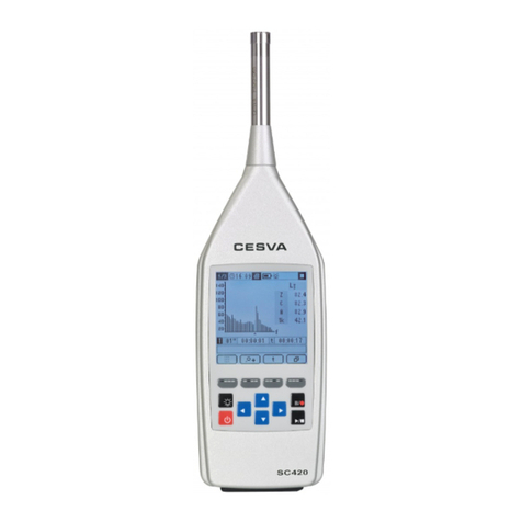
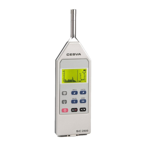
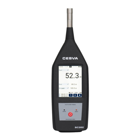
CESVA SC420 User manual

SC420
Sound Level Meter
Spectrum Analyser
USER MANUAL
M_SC420_v0016_20171215_EN


1
Since its beginnings in Barcelona in 1969, has been devoted to
manufacturing sound equipment and instrumentation through research,
development and innovation, and by registering its own patents.
We belong to national and international committees for the establishment and
revision of standards and regulations.
has a fast and efficient distribution network in over 40 countries
around the world.
We offer our customers an after-sales service to ensure the long life of our
instruments. Periodic tests and calibration services are also available.
Our website is the focal point for finding information on our products, requesting
no-obligation quotes, downloading software, contacting us and being kept
updated about all the training events and exhibitions we are present at on a
regular basis.
Taking care of our customers and listening to what they tell us means we are
closer to them and are able to offer the measurement solution that fully meets
their needs.
The Bluetooth trademark is the property of Bluetooth SIG, Inc.

2 Contents
1. What does this manual cover? 8
2. Equipment and literature 9
3. General device description 10
3.1 SC420 sound level meter spectrum analyser 10
3.2 Main features of the SC420 11
3.3 Device components 14
4. Inputs and outputs 16
4.1 SC420 inputs and outputs 16
4.2 Communications inputs and outputs 17
4.3 AC Output 17
4.4 Digital inputs and outputs 17
5. Keypad 19
6. Screen 21
6.1 Indicator area 21
6.2 Work area 23
6.3 Timing area 23
6.4 Memory area 24
6.5 Contextual area 24
7. Power 25
7.1 Power sources 25
7.1.1 Battery power 25
7.1.2 Power via USB 26
7.1.3 Mains feeder 26
7.2 Energy saving 26
7.3 Power for environmental monitoring 26
8. Assembling and dismantling the device 28
8.1 Windscreen 28
8.2 Extension cable 29
8.2.1 Removing and connecting the preamplifier 29
8.2.2 Connecting the extension cable 30
8.3 Outdoor kit 31
Contents

Contents 3
9. Switching the device on and off 32
9.1 Switching the device on 32
9.1.1 Initial SC420 self-check 33
9.2 Turning the device off 34
9.3 Switching the light on and off 34
10. Checking the device 35
10.1 Checking the SC420 35
11. Measuring and recording 37
11.1 Prior steps 37
11.2 Taking a measurement 38
11.3 Making a recording 38
11.4 Overload indicator 39
11.5 Under-range indicator 40
12. Menu 41
12.1 Accessing the menu 41
12.2 Menu areas 42
12.3 Navigating through the menu 42
13. Measurement modes 43
13.1 Selecting the measurement mode 43
13.2 Sound level meter mode 44
13.2.1 Sound level meter mode functions 44
13.2.2 Sound level meter mode prior adjustments 45
13.2.3 Sound level meter mode screens 45
13.3 1/1 spectrum analyser mode (OPTIONAL) 48
13.3.1 1/1 spectrum analyser mode functions 48
13.3.2 1/1 spectrum analyser mode prior adjustments 49
13.3.3 1/1 spectrum analyser mode screens 49
13.4 1/3 spectrum analyser mode (OPTIONAL) 52
13.4.1 Spectrum analyser mode 1/3 functions 53
13.4.2 1/3 spectrum analyser mode prior adjustments 53
13.4.3 1/3 spectrum analyser mode screens 53
13.5 Octave (1/1) and third octave (1/3) band reverberation time
(interrupted noise method) modes (OPTIONAL) 57
13.5.1 Octave (1/1) and third octave (1/3) band reverberation
time (interrupted noise method) mode functions 57
13.5.2 Taking a measurement in octave (1/1) and third
octave (1/3) band reverberation time (interrupted noise
method) modes 58
13.5.3 Screens in the octave (1/1) and third octave (1/3)
band reverberation time (interrupted noise method)
modes 59
13.6 Octave (1/1) and third octave (1/3) band reverberation time
(integrated impulse response method) modes (OPTIONAL) 62

4 Contents
13.6.1 Octave (1/1) and third octave (1/3) band reverberation
time (integrated impulse response method) mode
functions 63
13.6.2 Taking a measurement in octave (1/1) and third
octave (1/3) band reverberation time (integrated
impulse response method) modes 63
13.6.3 Octave (1/1) and third octave (1/3) band reverberation
time (integrated impulse response method) mode
screens 65
13.7 Occupational noise mode (OPTIONAL) 68
13.7.1 Occupational noise mode functions 68
13.7.2 Occupational noise mode prior adjustments 68
13.7.3 Occupational noise mode screens 69
13.8 FFT frequency analyser mode (OPTIONAL) 71
13.8.1 Taking an FFT measurement 71
13.8.2 FFT frequency analysis mode screen 72
13.9 Audio recording mode (analysis quality) (OPTIONAL) 73
13.9.1 Making an audio recording (analysis quality) 73
14. Advanced options 75
14.1 Zoom 75
14.2 Backerase 76
14.3 Marking 77
14.4 Voice comments 78
14.5 Audio recording (listening quality) 79
14.6 Automatic settings: Timers and triggers 80
14.6.1 Start measurement/recording automatically 80
14.6.2 Automatically stop measuring/recording 81
14.6.3 Automatic audio recording 83
14.6.4 DEN intervals 84
14.6.5 Examples of automatic measurement settings 85
15. Settings and adjustments 90
15.1 Accessing the settings sub-menu 90
15.2 Navigating through the settings sub-menu 90
15.3 Settings sub-menu 91
15.3.1 MEASUREMENT option 91
15.3.2 RECORDING option 93
15.3.3 AUTOMATISMS option 95
15.3.4 DATE AND TIME option 98
15.3.5 MICROPHONE SETTING option 98
15.3.6 CONTRAST option 100
15.3.7 AC OUTPUT option 100
15.3.8 BLUETOOTH®wireless communication/PRINTER
option 101
16. Registers and memory management 102

Contents 5
16.1 Saving a final result 102
16.2 Making a recording 105
16.2.1 Types of recording 105
16.3 Structure of a register 111
16.4 Viewing and deleting registers 112
16.4.1 Viewing registers 113
16.4.2 Deleting registers 114
16.5 Deleting the card memory 114
17. Using the inputs and outputs 115
17.1 Digital inputs and outputs and AC output 115
17.1.1 AC Output 115
17.1.2 Digital input 116
17.1.3 Digital output 116
17.2 Communicating with a PC, downloading data and
communicating with a printer 117
17.2.1 Memory card 117
17.2.2 RS-232 communications 118
17.2.3 USB communications 119
17.2.4 Bluetooth®wireless communication 119
17.3 PC software 120
18. Accessories 121
18.1 Accessories supplied 121
18.2 Optional accessories 121
19. Technical specifications 123
19.1 REFERENCE CONDITIONS 123
19.2 MICROPHONES AND PREAMPLIFIERS 124
19.2.1 Microphone models and their main features 124
19.2.2 Sound field correction for periodic tests 124
19.2.3 Frequency response 129
19.2.4 Directional response 135
19.2.5 Effect of the optional accessories on the microphone136
19.2.6 Preamplifier connector 137
19.3 MEASUREMENT 137
19.3.1 Warm-up time 137
19.3.2 Measurement range 138
19.3.3 Linearity range 138
19.3.4 Noise 139
19.3.5 Information for testing compliance withdrawn
standards IEC 60651 and IEC 60804 140
19.3.6 Time and clock features 141
19.3.7 Frequency weighting 141
19.4 CALIBRATION 142
19.5 OCTAVE AND THIRD OCTAVE BAND FILTERS 143
19.5.1 Octave and third octave band filters 143

6 Contents
19.5.2 Measurement range (octave band spectrum analyser)144
19.5.3 Measurement range (third octave spectrum analyser)145
19.6 REVERBERATION TIME 146
19.6.1 Measuring the decay curve and impulse response 146
19.6.2 Calculating the decay curve from the impulse
response 146
19.6.3 Estimating the slope of the decay curve 146
19.6.4 Reverberation time measurement lower limit 146
19.6.5 Quality indicators 146
19.6.6 Lower limit for reliable results obtained through a filter
and a detector 146
19.7 FFT 147
19.8 AUDIO RECORDING 147
19.9 ENVIRONMENTAL, ELECTROSTATIC AND RADIO
FREQUENCY CRITERIA 148
19.9.1 Stabilisation time 148
19.9.2 Environmental criteria 148
19.9.3 Electrostatic criteria 148
19.9.4 Criteria for fields at the frequency of the mains supply
and radio frequency fields 148
19.9.5 Influence of vibrations 149
19.10 INPUTS AND OUTPUTS 150
19.10.1 AC Output 150
19.10.2 Digital output 151
19.10.3 Digital input 151
19.10.4 MicroSD memory card slot 152
19.10.5 USB communication 152
19.10.6 RS-232 serial communication 152
19.10.7 Wireless communication 152
19.11 SCREEN 152
19.12 POWER 153
19.12.1 Batteries 153
19.12.2 External Supply 153
19.13 DIMENSIONS AND WEIGHT 153
19.14 STANDARDS 153
19.14.1 Standards 153
19.14.2 Standards of measurement and calculation 154
19.14.3 Certificates 154
19.14.4 Notes 154
20. Maintenance and precautions 155
21. Guidance on taking measurements 157
22. Activating optional modes 158
23. Functions 159
23.1 Function nomenclature 159

Contents 7
23.1.1 Sound level meter mode functions 159
23.1.2 1/1 spectrum analyser mode functions 161
23.1.3 1/3 Spectrum analyser mode functions 162
23.1.4 Octave (1/1) and third octave (1/3) band reverberation
time mode functions 164
23.1.5 Occupational noise mode functions 165
23.1.6 FFT analyser mode functions 165
23.2 Function description 166
23.2.1 Sound pressure level with Fast and Slow time
weightings 166
23.2.2 Sound pressure level with Impulse time weighting 167
23.2.3 Peak sound pressure level 167
23.2.4 Equivalent continuous sound pressure level 167
23.2.5 Taktmaximal-Mittelungspegel 168
23.2.6 Sound exposure level (SEL) 168
23.2.7 Percentile levels 169
23.2.8 Decay curve 169
23.2.9 Impulse response 169
23.2.10 Integrated impulse response method 169
23.2.11 Reverberation Time 169
23.2.12 Quality parameters (ξ , C and B·T values) 170
23.2.13 Equivalent daily noise exposure level 170
23.2.14 Sound exposure 171
23.2.15 Dose 171

8 Chapter 1 What does this manual cover?
This manual contains all the information you will need to get the most out of the
device you have just purchased.
This information is divided into 7 sections:
The first section has chapters on the main features of the device and its physical
components (chapters 3, 4, 5, 6, 7 and 8).
The second presents how the device can be used to take measurements,
whether in sound level meter mode, spectrum analyser mode, reverberation time
mode, etc. (chapters 9, 10, 11, 12 and 13).
The third section presents the device's range of advanced options, which make
this a versatile tool that closely adapts to the needs of each user (chapter 14).
The fourth section focuses on configuring the device: menu structure and
directions for carrying out the various adjustments (chapters 15 and 16).
In the fifth section, other important topics are covered, such as connecting to a
PC, accessories (chapters 17 and 18).
The sixth section contains the technical specifications that explain the equipment
you are working with in detail (chapter 19).
Finally, the seventh section encompasses several chapters that provide
information such as: Maintenance and precautions, guidance on taking
measurements, function nomenclature and descriptions, etc. (chapters 20, 21, 22
and 23).
What does this manual cover?
1. What does this manual cover?
1
NOTE: If you are already familiar with the device and only wish to consult the
information on taking measurements, please see chapters 9, 10, 11, 12 and
13.

Chapter 2 Equipment and literature 9
The first step is to check that all the equipment and literature supplied with the
device is there:
Material:
SC420 sound level meter
PV009 windscreen
Two AA size 1.5 V alkaline batteries (LR6)
CN400 USB-to-micro-USB cable for communication with a PC
MicroSD memory card
PC communication software to download, display and edit data:
Lab
Literature included:
Sound level meter user's manual
Warranty
Should any of these elements be missing, please contact your official distributor.
Equipment and literature
2. Equipment and literature
2

10 Chapter 3 General description of the device
This chapter provides a general description of the SC420 sound level meter. This
description will introduce you to all the possibilities offered by the SC420 and its
main features. It will also help you to identify the various components of the
device.
3.1 SC420 sound level meter spectrum analyser
The SC420 is more than a sound measuring instrument —it is the ideal tool for
the noise professional thanks to its high capacity, versatility and ease of use.
The SC420 is a sound level meter that meets the specifications of IEC 61672
international standard for class 1 (see table) for both response to sound waves
incident on the microphone in the reference direction in a free field and for
response to randomly incident waves in a diffuse field (sound field correction
configured for diffuse field).
The SC420 also meets American standards ANSI S1.4 and ANSI S1.43, as class
1 (see table), for sounds from several angles (sound field correction configured
for diffuse field):
MICROPHONE
ASSOCIATED PREAMPLIFIER
CLASS according to IEC 61672-1 and ANSI
C-130
PA020
1
C140
PA020
1
C240
PA040
1
The basic version of the SC420 disposes the SOUND LEVEL METER
measurement mode. It also offers the possibility of extension with different
modules:
Real time spectrum analyser module in octave bands (1/1) with class 1 filters
as per standard IEC 61260
Real time spectrum analyser module in third octave bands (1/3) with class 1
filters as per standard IEC 61260
Reverberation time measurement (interrupted noise method) module (in 1/1
octave and third octave 1/3 bands)
Reverberation time measurement (integrated impulse response method)
module (in 1/1 octave and third octave 1/3 bands)
General device description
3. General device description
3

Chapter 3 General description of the device 11
Occupational Noise functions evaluation module
FFT narrow band frequency analysis module
Analysis quality audio recording module
When used with the appropriate modules, the SC420 is a sound level meter that
you can use to take any kind of measurement: measurements of acoustic
insulation and reverberation time in buildings, measurement of environmental
parameters (tonal, impulsive and low frequency components), analysis of
industrial noise produced by machinery, exposure noise evaluations, etc.
Its ergonomic form means it can be used as both a hand-held instrument for in-
situ measurements and as a device for carrying out continuous noise monitoring.
The SC420 has advanced features such as: audio recording for recognition and
reanalysis, automatic start and stop functions for measuring and audio recording
by timers and threshold, extendible memory through cards, Backerase, USB
connectivity, Bluetooth®wireless communication and 3G, ADSL, Wi-Fi
communication capabilities, etc.
3.2 Main features of the SC420
The SC420 it is a high performance sound level meter with the following main
features:
THE PHILOSOPHY:
The SC420 keeps the philosophy of producing instruments that
are powerful, simple and easy to use.
Single range: no need for prior configuration of the SC420 measurement
range to match the dynamic range of the sound event to be measured.
In each of its modes, the SC420 measures all functions simultaneously. There
is no need to configure time weighting or frequency weightings (A, C or Z).
The SC420 measures on three different time bases simultaneously: global
values corresponding to the total measurement time (t), time history of
consecutive partial values (T) configurable to between 1 second and 1 hour,
and "Short Leq" time history every 125 ms. When measuring decay curves for
reverberation time evaluation, a basis of 10 ms is used.
This is all you need to do measurements: Switch on and
measure. At the touch of just two buttons, the SC420 measures all the
required parameters.
BACKERASE:
With the Backerase option, the SC420 can delete the last 10 seconds of the
measurement in progress. This option is ideal when unwanted noise events
occur during measurement (see 14.2).
The Bluetooth trademark is the property of Bluetooth SIG, Inc.

12 Chapter 3 General description of the device
MARKS:
This option allows the user to identify different stretches during measurement;
this is a great help during post-processing since it means you can go directly
to the stretches marked during the measurement (see 14.3).
microSD CARDS and DOWNLOADING DATA:
Data measured by the SC420 can be saved on removable microSD cards
(see 20), thus creating greater flexibility in data storage. The functions stored
are configurable and the recording mode can be adapted to the type of
measurement to be taken (see 15.3.2).
The SC420 has Lab software that allows you to download any
data recorded to a PC, in order to have them available in electronic format and
export them to other programmes to create your own reports (see 17.3).
Downloading data using Lab can be done simultaneously with the
measurement or recording processes. This feature, together with the option to
erase measurement periods as they are downloaded, makes the SC420 the
perfect platform for permanent acoustic monitoring (see 17.2).
You can also remove the microSD card, insert it into a PC and import data
using the Lab software. While the full card downloads, the SC420
can continue saving results on a new card. This is an alternative way to take
long measurements without loss of data (see 17.2.1).
The file system used by the SC420 is optimised for downloading large
amounts of data, optimising the download time and facilitating the resumption
in case of failure of the communication channel.
INNOVATIVE DESIGN:
The ergonomic shape of the SC420 has been designed to minimise the
effects of any reflections or diffractions and provide a comfortable and firm
grip.
The 3.2" graphic display allows data to be shown both numerically and
graphically. The graphic display is highly practical when it comes to studying a
sound event, evaluating its time history or analysing its spectral content. It
also has an automatic zoom option for looking at highly stable noise events in
more detail (see 14.1). The SC420's screen can be read clearly and precisely
in full daylight; it can also be illuminated at the touch of a button, allowing the
user to work in low-light conditions as well.
The SC420 has an intuitive keypad with four keys dedicated to the main
functions, four contextual keys (softkeys) that adapt to the information
displayed on the screen and four selector keys (joystick) to facilitate
navigation through its menu structure (see 5).
The SC420 supports both prepolarised and polarised 200 V microphones.
Each type of microphone needs its corresponding preamplifier. These can be
removed in order to attach CN003, CN010 or CN030 extension cables or
TK200 outdoor kit for measurements taken outside (see 8).
ICON MENU:
The device is configured using menus composed entirely of easily identifiable
and recognisable icons, with no need to set languages.

Chapter 3 General description of the device 13
AUDIO RECORDING, TIMERS AND TRIGGERS:
While it is taking measurements, the SC420 can also record audio files for
recognition of sound sources (listening quality) (see 14.5), for voice comments
(see 14.4) and for post-processing (quality analysis) (see 13.9).
The SC420 has a complete system of automatic settings for starting and
stopping measurement and audio recording using automatic timers and
triggers activated by exceeding the threshold by time intervals. This extends
even further more the possibilities of the SC420 as a stand-alone unit for
continuous noise monitoring (see 14.6).
The power for environmental monitoring option allows the SC420 to resume
recording after recovering from a power cut (see 7.3).
COMMUNICATIONS:
The SC420 can communicate with a PC via a USB port, Bluetooth®wireless
communication or RS-232 serial port for downloading data, programming or
control and visualisation in real time. Communication is also possible via 3G,
ADSL and Wi-Fi (see 17.2).
The RS232 port of the SC420 can be configurated to connect a serial printer.
In SLM mode and octave 1/1 band spectrum analyzer mode, the SC420
sends in real-time the values of the measured functions (see 17.2.2).
The SC420 has a multi-contact connector which makes available: the AC
signal from the microphone, the digital inputs and outputs for control and the
RS-232 serial communication port (see 17).
LOG OF CHANGES:
Saved in its memory, the SC420 has a log of the last five modifications of
changes to date and time and adjustment of sensitivity, with the date and time
when they were carried out.

14 Chapter 3 General description of the device
3.3 Device components
The following diagram shows the main components of the SC420:
1. ½" precision condenser microphone ·The SC420 complies as class 1 (see
3.1).
2. Preamplifier ·The preamplifier on the SC420 is removable and should match
the preamplifier model associated with the microphone (see 3.1). The
preamplifier is connected using the LEMO connector (3).
3. Preamplifier LEMO-type connector ·LEMO-type male connector or the
preamplifier. This is protected by the protective cone.
4. Sound level meter LEMO-type connector ·LEMO-type female connector for
the sound level meter of the SC420. This is protected by the protective cone.
5. Protective cone ·Cone that covers the female sound level meter and the male
preamplifier LEMO connectors to protect them.
6. Screen ·Large 3.2" backlit LCD graphic screen.
7. Membrane keypad ·Extra flat keypad that minimises reflection.
8. Manufacturer information · Area where the brand origin of design and
manufacture are indicated.
9. IEC marking ·This area displays the sound level meter model and serial
number, as well as the IEC standards that it meets.
10. Space reserved for the periodic test label ·Space reserved for the label of
compliance with the sound level meter periodic test (as per IEC 61672-3).
11. Class information · This area displays the classification of the sound level
meter in terms of compliance with the standards specified in the IEC and ANSI
marks, depending on the microphone.
12. ANSI mark ·Area that indicates the ANSI standards met by the SC420.
13. Tripod support ·Flush tripod support with ¼’" W standard thread. (TR040 and
TR050).
14. WEEE marking ·Indicates the separate collection of electrical/electronic
appliances.
15. CE marking ·European conformity mark.
16. Protective battery cover · Protective battery cover: only remove to change
batteries.
17. symbol ·The SC420 has Bluetooth®wireless communication.
18. Protective connector cover ·Cover to protect the connectors from possible
damage.
19. USB connector · Micro-B USB connector for digital communication and power.
Complies with USB rev. 2.0.
20. Memory card slot ·Slot for microSD memory cards.
21. Multi-connector ·This connector has different inputs/outputs (AC output, digital
input/output and RS-232 serial port).

Chapter 3 General description of the device 15
1
23
5
6
7
4
8
9
10
11
12
13
14
15
16 17
18
19 20 21

16 Chapter 4 Inputs and outputs
This chapter describes the digital and analogue inputs and outputs of the SC420.
It describes how to identify and configure them, and how to extract data and
signals from them.
The SC420's inputs and outputs are on the bottom of the device, protected by a
removable protective cover. To access them, lift the cover, remembering to put it
back once you have finished.
4.1 SC420 inputs and outputs
The SC420 has the following inputs and outputs:
19 20 21
1. USB [19]: Input/output for two-way digital USB communication with a PC and
for powering the device. Complies with USB rev. 2.0. To connect the SC420 to
a PC through this input, use cable CN400.
2. Memory card slot [20]: Slot for a microSD memory card. The data recorded by
the sound level meter, functions and audio are stored on this card. Larger
capacity cards can cause permanent damage to the device (see 20).
3. Multi-connector [21]: (Twenty-contact connector with various inputs and
outputs. To access these inputs and outputs, use CN420 cable:
RS-232 serial port. Input/output serial port for two-way digital communication
with a PC (see 4.2).
AC output. Analogical output directly proportional to the preamplifier output,
without frequency weighting (see 4.3).
Digital output. Digital output that takes values depending on whether the
automatic audio recording threshold is exceeded (see 4.4).
Inputs and outputs
4. Inputs and outputs
4
NOTE: For the device to function correctly, you should use at least a class 4
card. The card class determines the write speed; therefore, the higher the
card class is, the faster the SC420 will work.

Chapter 4 Inputs and outputs 17
Digital input. Digital input that enables a measurement to be started or
stopped and marks to be inserted, depending on its state (see 4.4).
4. Bluetooth®wireless communication. Wireless input/output for two-way digital
communication with a PC via radiofrequency (see 4.2)
4.2 Communications inputs and outputs
The SC420 can communicate with a PC via the Lab, USB,
Bluetooth®wireless communication or the RS-232 serial port. The SC420 allows
the connection to a serial printer too (see 17.2).
To use the RS-232 serial input/output, use the CN420 cable, inserting the cable's
male multi-connector into the female SC420 multi-connector. On the RS-232
SERIAL connector, at the opposite end of the cable, you will find this
input/output.
It is also possible to communicate via 3G, ADSL and Wi-Fi: for more information,
please consult your official distributor.
4.3 AC Output
The AC output contains an alternating current signal proportional to the output of
the preamplifier. This makes it possible to:
Listen to the sound event being measured and determine whether it is
influenced by noises other than those that you wish to measure.
Physically record said signal for recognition of the sound event being
measured or for reanalysis of the signal received by the microphone. This
option is possible using the SC420 itself (see 17.1.1).
To extract the aforementioned signal, use the CN420 cable, inserting the cable's
male multi-connector into the female SC420 multi-connector. The AC OUTPUT
connector has the AC output at the opposite end of the CN420 cable.
In order to adapt the dynamic range of the AC output to the hearing or recording
range, use the option in the CONFIGURATION menu (see 15.3.7).
4.4 Digital inputs and outputs
The SC420 has a digital input and a digital output. To work with them, use the
CN420 cable, inserting the cable's male multi-connector into the female SC420
multi-connector. You will find them on connectors DIGITAL I and DIGITAL O
respectively, at the opposite end of the CN420 cable.
The digital output takes values depending on whether the automatic audio
recording threshold is exceeded in each of the time zones. If the threshold is
exceeded, the signal in the digital output takes value 0; if it is not exceeded, the
value is 1 (see 17.1.3).

18 Chapter 4 Inputs and outputs
The digital input can start and stop a data recording depending on its state. The
START AUTOMATIC MEASUREMENT and STOP AUTOMATIC
MEASUREMENT options should be activated and configured with the DIGITAL
INPUT option (see 17.1.2). This input can also be used to insert markers while
recording data (see 14.3).
Other manuals for SC420
1
Table of contents
Other CESVA Measuring Instrument manuals