RF MOUNT HD User manual

MOUNT
INSTALLATION
GUIDE
17 Apr 2012

Mount Installation and Education Guide
2

Mount Installation and Education Guide
3
TABLE OF CONTENTS
DEFINITIONS ................................................ 5
Mount Rotation Definitions ...................... 6
Function of Antenna Movement................ 7
MOUNT COMPONENTS
Front........................................................... 8
Rear............................................................ 9
INSTALLATION MOUNTING PADS ......... 10
INSTALLATION OF vGPS ............................11
vGPS for DirecTV.............................................12
vGPS for SHAW Direct ...................................13
FEATURES AND OPERATION.................... 14
MOUNT ROTATIONAL CLEARANCES.... 15
BILL OF MATERIALS................................... 16
MOUNTING HINTS....................................... 17
WIRING DIAGRAM...................................... 18
ROOF CONNECTOR HOUSINGS ............... 19
FIELD SERVICE RELATED PARTS.......... 20
SUPPORT ......................................................... 21
Parts return procedure
Support contact information

Mount Installation and Education Guide
4
NOTES

Mount Installation and Education Guide
5
DEFINITIONS
The mount consists of several components that make it up.
DISH, REFLECTOR, PARABOLA
Receives signal from the satellite and reflects it into the LNB.
LNBF Receives the focused signal from the dish and blocks the noise from the signal and sends it to the satellite
receiver by way of the coax, hence, it is called a Low Noise Blocker (Feed).
vGPS OR SIDECAR
Used to triangulate and calculate skew.
LNB ARM
Holds the LNB in the proper focal point of the Dish.
DISH SUPPORT ARMS
Attaches the dish and skew assembly to the Base Unit.
SUPPORT ARM ATTACHMENT BOLTS
Securing bolts that secure the Dish Support Arms to the Base Unit.
BASE UNIT
Performs the rotating functions in both Azimuth and Elevation. It is attached to the roof of the RV by screws
or bolts.
Dish, Reflector, Parabola
LNBF
vGPS
LNB Arm
Dish Support Arms
Base Unit
Dish, Reflector, Parabola

Mount Installation and Education Guide
6
MOUNT ROTATIONS
The mount will use the rotation of three (3) axis to achieve acquisition. Terminology is helpful when
conversing with your installing dealer or a factory support technicians. Earlier in this manual you were
given instruction concerning the components of the mount. We will now discuss the rotation of the mount
and what is accomplished with each movement.
Rotation of the base in a clock
wise/counter clockwise is call
AZIMUTH
Tilting of the antenna from side
to side is called SKEW
The antenna in the travel
position is called STOWED
To FRONT of vehicle
Antenna in the upright position
and not moving is called
DEPLOYED
Movement of the antenna from the STOWED position
to the DEPLOYED position is called ELEVATION

Mount Installation and Education Guide
7
FUNCTION OF ANTENNA MOVEMENT
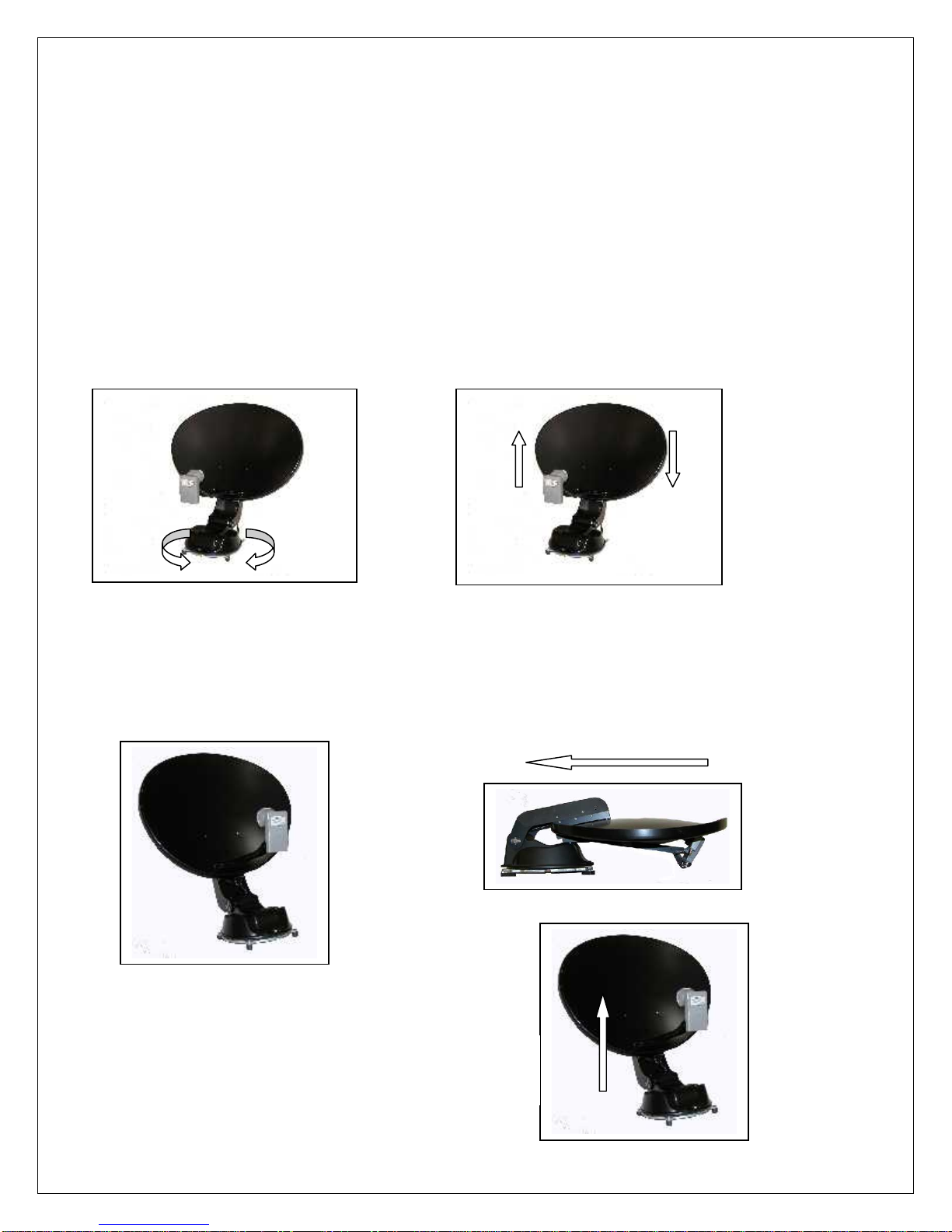
AZIMUTH
Once the antenna is deployed, the Controller (Indoor Unit) will instruct the mount to rotate clockwise
and then counter clockwise to sweep the sky for satellites. If the system does not see a satellite that it can
identify once it rotates to its clockwise or counter clockwise, as it stops against an azimuth limit it will go up
2 degrees and reverse directions. If it does not see a satellite that it can identify on this pass when it hits the
opposing limit it will go down 4 degrees in elevation. If nothing seen, it will go up 6 degrees, ever widening
its search pattern until it has swept a "box" in the sky. If nothing is found in this search pattern the system
will display an error as to what it thinks is wrong.
SKEWOnce the controller has identified two satellites or has input from a vGPS, it will calculate the arc in
which the satellites reside and tilt the antenna (and LNB's) to align each LNB at the end of the LNB Arm
with their appropriate satellites. If you travel from Southern Florida to Southern California the skew angle
will change dramatically. It will tilt or skew the antenna an opposite or more extreme direction. It will
change somewhere in the middle of the country depending upon the satellites that you are looking for.
DEPLOYED
If the mount has quit moving it has probability acquired, identified and maintained a high signal lock
and you are probably watching TV.
STOWED
When the mount is given a command to stow, it will elevate fully to clear any object on your roof,
bring skew into a neutral position and then rotate in azimuth until it hits an azimuth limit. At that time it will
move down in elevation until it comes to rest in a travel position. This is an important step. This will
prevent the automatic stow feature that an overpass provides. (just checking to see if you were reading the
manual).
ELEVATION
The controller remembers its last elevation that it saw when it last identified a satellite. It will rise to
that specific elevation to shorten your search time. If the system has a vGPS then that device will provide
the controller with the proper required information for proper satellite acquisition.

Mount Installation and Education Guide
8
MOUNT COMPONENT (Front View)
Control cable and Coax
cables enter the mount
here.
Azimuth Limit Bar
Elevation Limit Sensor
Azimuth Limit Sensor
Elevation Motor/Gearbox
Assembly
Azimuth Motor/Gearbox
Assembly

Mount Installation and Education Guide
9
MOUNT COMPONENT (Rear)
SKEW ASSEMBLY
This assembly tilts the dish from side to side (skew) to align for polarity and satellite positioning or
both.
DISH ARM COVER
Covers and protects the Skew Motor mechanism from the elements. Provides protection from tree
limbs etc. that it may encounter in the stowed position when the RV is moving.
Skew Assembly
Dish Arm Cover
Skew Motor/Gearbox
Assembly
Skew Chain
Dish Backing or Skew
Mounting Plate
Azimuth Base Cover

Mount Installation and Education Guide
10
INSTALLATION MOUNTING FEET (PADS)
The Mount will be shipped
with the Mounting Pads
rotated into the "shipping"
position. They will be
rotated and secured prior to
installation. For roofs that
have a stable platform they
may be installed in this
position.
The Mount will be shipped
with the Mounting Pads
rotated into the "shipping"
position. They will be
rotated and secured prior to
installation. For roofs that
have an unstable platform
they may be installed in the
"open" position.
INSTALLATION MOUNTING PADS

Mount Installation and Education Guide
11
INSTALLATION OF vGPS
The vGPS is a device that is affixed to the DirecTV SWM or SHAW Direct LNB. It is used in the
acquisition sequence of controller. It is critical that the vGPS be installed and wired according to the
following information. Failure to do so will make the system inoperable.
vGPS
The coax cable with the YELLOW sleeving must
be connected to the vGPS.
vGPS Bracket

Mount Installation and Education Guide
12
vGPS BLOCK DIAGRAM
SWM
SWM
LNB
vGPS
Yellow Sleeve
DiSEqC
Switch
Denotes power path
Optional Receivers
Mount
Receiver
Receiver
To SWM
Note: The SWM LNB
has 8 channels available.
Each DVR takes 2
channels (one coax). A
non DVR uses one
channel (one coax). You
may use any combination
of receivers until you use
up all 8 channels.
Example: A HR34 uses 5
channels leaving 3
channels available.
Shown with SWM 4
Position Splitter

Mount Installation and Education Guide
13
vGPS BLOCK DIAGRAM
SHAW Direct

Mount Installation and Education Guide
14
FEATURES AND OPERATION
The mount is designed to respond from electronic signals from the controller (In Door Unit) to raise it
from its stowed position and align itself automatically on the selected satellite(s).
To operated the system follow these steps:
1. Initially you will want to make sure the Dip Switches are set properly based on your configuration
requirements.
2. Turn ON Power to the controller
3. If you want to raise the dish or search for satellite(s), press SEARCH
4. If you want to stow the dish, press STOW
5. The RFM-1000/1100 Controller will automatically shut OFF power after completing SEARCH or
STOW procedure.
If you want to watch satellite TV, after following the above procedures:
1. Turn ON your TV
2. Turn ON your satellite receiver
3. If you have a Distribution box, set your switches to the proper settings for satellite TV.
This mount is "Field Serviceable". Most components that make up this mount may be replaced or
repaired in the field by the consumer or a RF Mogul dealer. There is practically no part of this mount
that cannot be repaired or replaced in the field.

Mount Installation and Education Guide
15
ROTATIONAL CLEARANCES
LOOK ANGLE LIMITS
Look angle for Northern limits are
EAST Lat 49°
Long 65°
This is approximately a 18° look angle for the reflector.
WESTLat 61°
Long 136°
This is approximately a 15° look angle for the reflector
Look angles for Southern limits are
WESTLat 24°
Long 107°
This is approximately a 65° look angle for the reflector
This does not say that you will be able to see the signal at these angles, only that the dish is capable of
moving to these extremes at these coordinates. Consult your programmer for viewing capabilities.
If you don't understand these
measurements, please contact our
Technical Support Department.
MOUNT FOOTPRINT
(When Stowed)
Dish Size Width Length
75 cm 36" 37.0"
Height 10.5"

Mount Installation and Education Guide
16
BILL OF MATERIALS
Your system, when ordered as a system, comes with the following items:
1 ea. Mount consisting of the base, reflector, LNB Arm and LNB (the Mount)
1 ea. LNB Landing Plate
15 ft. 20 gauge, 12 conductor control cable (terminated on the mount end)
1 ea. 12 pin connector for securing the control cable to the controller
1 ea. Controller (Indoor Unit)
1 ea. 12v 7 amp Power Supply for the controller
1 ea. User Guide
1 ea. Product Registration Card
If the system is DirecTV SWM or SHAW Direct you will receive..
1 ea vGPS
1 ea vGPS Mounting Bracket
Things that the installing dealer will supply:
Sealant for sealing during installation
Screws for securing the mount, LNB Landing plate and Connector Housing to the roof
RG6U coax
Coax connectors
Loom for encasing cable on the roof (optional)
Cable clamps or straps used to secure the cables to the roof (optional)
What is required but not supplied
Common sense

Mount Installation and Education Guide
17
MOUNTING HINTS
The steps outlined here will help you determine what is important to you when installing your RF
Mogul satellite television system. They are not expected to give you every detail of the installation
procedure but will provide an overview.
Position the mount in this manner for Direction of travel
It is recommended that you place the mount in the centerline of the RV. It is not required but
recommended. The mount is designed to handle slightly curved roofs because of the nature of the
Mounting Feet.
Seal beneath the mounting feet to prevent moisture from penetrating the holes made by the
attachment screws. Use the all screw holes in the mounting feet that are necessary to complete a
proper installation.
Use proper sealant whenever penetrating the roof during installation. A trick would be to screw
through the sealant rather than just surrounding the penetration.
Leave at least a 6" Service Loop when determining length of cable to use. It may be necessary to cut
the cable to replace connectors in the future and you will want some slack when doing so.
Always use a Dielectric gel or grease on all out door electrical connections to prevent moisture
damage.
Find a location for the mount that will accommodate the shortest cable runs as possible.
Allow for proper clearance to prevent the mount from hitting things like the air conditioner, radio
antenna, off air television antenna, solar panels etc.
Base points to the FRONT of the vehicle.
Antenna points to the REAR of the vehicle.

Mount Installation and Education Guide
18
WIRING DIAGRAM
For Dish Network, BELL TV and SHAW Direct Configurations
Satellite Receiver #4
##1#1
Satellite Receiver #3
Satellite Receiver #2
Satellite Receiver #1
To TVs
DC Power Supply
Your configuration may vary with the
number of coax cables run*.
RED indicates Control cable from roof Mount
RFM-1000/1100
controller
*This wiring diagram depicts 4 coax cables. The mount is wired standard with 2
(or one(1) in the case of DirecTV SWM)). Your application may require more
coax cables. Up to two (2) more coax cables can be inserted into a mount except
the DirecTV SWM mount as this mount will only have one cable. It is
recommended that the installing dealer acquire and stock additional mount coax
cables. See details for running additional coax cables.
1
2
3 Optional
4 Optional*
This coax cable has a BLACK sleeve or band
as it exits the mount. Do not use any other
color sleeve to connect to the controller.
DirecTV SWM requires just a single
coax cable for its SWM service.
Multiple coax cables are not required.
See "vGPS Block Diagram" in this
manual for more details.
*It should be noted.... The Dish Network and
Bell TV HAS ONLY 3 COAX OUTPUTS
FROM THE LNB.

Mount Installation and Education Guide
19
HOUSINGS
Control/RG6U Cable Connector Housing
positioned next to the mount
Cable Clam Shell
covers the entry hole of the
Control and RG6U cables
This covering will house
1 Control Cable and,
Up to 4 RG6U Coax
Cables
Housing will be manufactured
of black plastic material.
This covering will house
1 Control Cable, and
Up to 4 RG6U Coax
Cables
Shown with Control Cable
Connector and no cables.
Housing will be manufactured
of black plastic material.
NOTE:
The Connector Housing will not be sealed
with Dicor, only the screws that attached the
inner plate to the roof will require sealing (not
the cover).
HOUSINGS
For protection of cable connections and roof entry hole
Note:
The Clam Shell will require sealing with
Dicor. Specifically the cables as they enter
the shell, and the shell itself.
From Mount
To Controller

Mount Installation and Education Guide
20
FIELD SERVICE RELATED PARTS
Your mount consists of several "field serviceable" components. Depending upon your warranty
status the parts may require purchasing. The pricing given in this manual is give to provide you an estimate
of the cost of the part. It is not intended to be the actual price.
Description Part Number Associated Cost
Motor Azimuth
Elevation
Skew
Sensor Azimuth
Elevation
Covers Azimuth
Elevation Arm (skew)
Cable Control 15'
Control 30'
Control 40'
LNB DirecTV SWM 3 LNB
Dish Network 3 LNB
BELL TV 3 LNB
SHAW Direct E75 XKU Triple Satellite LNB
Controller
RFM 1000/1100
Power Supply
12 VDC, 7 amp.
Reflector
SHAW Direct 75cm
DirecTV 75cm
Dish Network HD/ BELL TV 75cm
LNB Arm Assembly
SHAW Direct
DirecTV
Dish Network HD/ BELL TV
This manual suits for next models
1
Table of contents
Popular Antenna manuals by other brands

AXIL
AXIL AN 0264 L user manual

ZyXEL Communications
ZyXEL Communications ZoneDAS user guide

Alpha Antenna
Alpha Antenna HOA Buster user guide

BARKER & WILLIAMSON
BARKER & WILLIAMSON AP-10B quick start guide

CommScope
CommScope CMAX-LHM2-30-I53 installation instructions

Carbest
Carbest Multi-Sat X65 instruction manual

Vivanco
Vivanco BOOSTED DIGITAL DVB-T OUTDOOR ANTENNA MAX.... operating instructions

Clas Ohlson
Clas Ohlson WS-101 manual

Retro Antenna
Retro Antenna PA-02 installation instructions

Digital Antenna
Digital Antenna GLOBAL MARINE CELLULAR ANTENNA 9dB GAIN MULTI-BAND 800... Specification sheet

Electrovision
Electrovision T143EB quick start guide

Rehau
Rehau NEA SMART 2.0 Quick install