RF RFT-855 User manual

RFT-855
2 MUX DVB-T/T2/C --> COFDM HD remux modulator
User Manual
RF-Tuote Oy, Joensuunkatu 13, 24100 Salo tel. +358-2736 6360, fa . +358-2-736 6355, info@rf-tuote.fi, www.rf-tuote.fi

1. Purpose of use
RFT-855 is designed for a processing two DVB-T2 mux programs into two DVB-T mux.
2. Installation
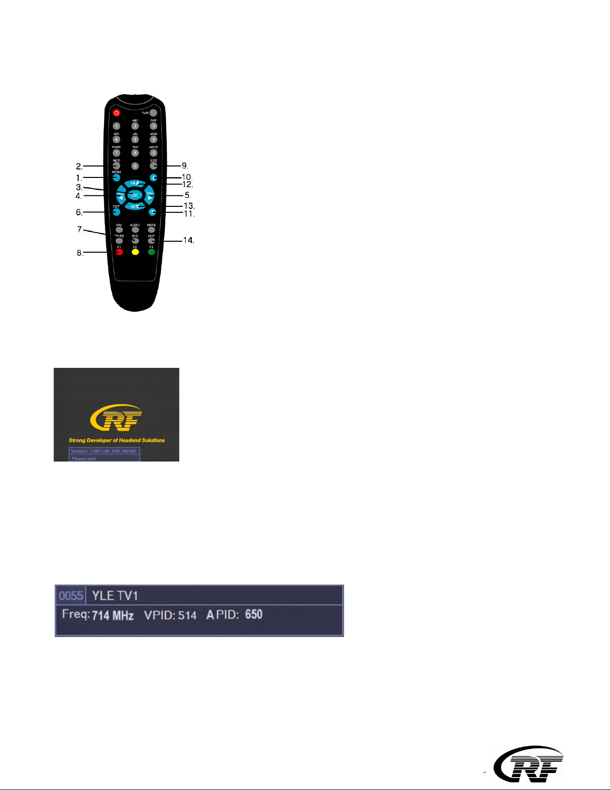
The connections and indications are shown in Fig 1.
1. Control switch to program channel 1 (left) or channel
2 (right). The switch must be set to middle position when
programming is ready
2. Channel number ( CCIR)
3. Cable-TV S channel indicator led
4. The signal led shows the output channel mode or that
the unit is powered
5. Signal led indicates that receiver is locked to selected
transport stream
6. ANT IN
7. USB ports are for possible software update
8. RF OUT + DC IN in RFT-800 frame installation
9. DC IN (only in stand-alone installation)
10. DC OUT for next RFT-831 unit (max. 4 units in
chain in stand-alone installation)
11. VIDEO/AUDIO connectors for monitoring
12. IR detector
13. CAM slot
14. Bit rate indicator. Red = overload, Green = under maximum
RFT-855 can be mounted either to RFT-800 system (RFT-800 User Manual) or stand-alone. Do not
cover the air passage holes.
Signals from antenna are fed to IEC-connectors at the top of unit.
When RFT-855 is mounted for RFT-800 frame, the power voltage is supplied through active output
combiner (RFC-808 or RFC-816). When RFT-855 is mounted stand-alone, power supply unit (RFP-804
or RFP-808) must be mounted to the left side of RFT-845 due to the ventilation. DC connector is
connected to left side of DC connector at the bottom of unit (9). You can loop-through DC from the
right side DC connector (10) to next unit with the DC cable. Maximum four RFT-845 units in chain can
be supplied with one power supply (RFP-804) in stand-alone installation (max. two units with RFP-
802).
When RFT-845 is mounted for RFT-800 system, cable to network is connected to active output
combiner (RFC-808 or RFC-816). When RFT-845 is mounted stand-alone, RF OUT (8) is connected to
cable network via external RF combiner (RFZ-802).
VIDEO/AUDIO connectors (11) are for monitoring the unit while programming.
NOTE! CA module (13) for smart card must be installed and removed only when power is OFF.
RF-Tuote Oy, Joensuunkatu 13, 24100 Salo tel. +358-2736 6360, fa . +358-2-736 6355, info@rf-tuote.fi, www.rf-tuote.fi

3. Programming
The receivers and modulators are simple to program with the remote control unit (RCU-800). The main
functions of RCU are shown in Fig 2.
1. MENU Main OSD menu
2. INFO Channel information
3. OK Confirm selection
4. VOL <
<<
<Audio volume, select left (audio output only)
5. VOL >
>>
>Audio volume, select right
6. EXIT Exit from menu
7. SYS Add or remove programs to output MUX
8. F1 BER
9. EPG Channel list
10. ∧∧
∧∧∧∧
∧∧ Scroll channel list one page at a time
11. ∨∨
∨∨∨∨
∨∨ Scroll channel list one page at a time
12. CH ∧
∧∧
∧Change a channel, select up
13. CH ∨
∨∨
∨Change a channel, select down
14. UHF UHF + ∧/∨= set output channel
Fig 2.
3.1 Power-up
At power-up this welcome screen is displayed. Main SW and user interface SW version numbers plus unit
serial number are shown.
When the unit is powered the display lights up showing selected output channels (Fig 1. no 2 ). The factory
set channels are E40 and E42.
The display is switched off after 3 minutes. Two signal led indicate that the unit is powered. The display
lights up again by pressing any button of remote controller unit.
Next program info for channel previously selected is displayed and the channel opened, if possible. Info
shows program name, transponder frequency, data rate, FEC and channel video PID number.
Please note that opening a channel will take longer time when a conditional access module is inserted. It is
recommended to use updated smart card. If the channel list is empty, welcome screen will remain
displayed.
RF-Tuote Oy, Joensuunkatu 13, 24100 Salo tel. +358-2736 6360, fa . +358-2-736 6355, info@rf-tuote.fi, www.rf-tuote.fi

3.2 First time set-up
When using the unit for the first time, you must first connect video and audio connectors to monitor. After
this you can continue set-up using on-screen menus.
To control the unit first slide front panel switch to left or right position to control receiver 1 or 2
respectively. When programming is ready, the front panel switch must be slide to center position. This will
prevent accidental changes to be made while controlling other units.
3.3 Set-up
To start set-up, press Menu key (Fig 2. no 1). Main Menu will be displayed.
Select “Configuration”.
Following settings can be selected:
- Audio Language (recommended ALL)
- NOTE! When MPEG-4 programs are received or scrambled channels are not descrambled (marked
with +) at the headend select “Modulator Menu”. Otherwise select “MPEG2 SD Monitor”.Start-Up
Select “Scan Multiplex” and write multiplex frequency. Then select “Scan”.
You can adjust frequency using numeric keys, left and right keys or double arrow keys.
When scanning is ready Channel List is shown.
RF-Tuote Oy, Joensuunkatu 13, 24100 Salo tel. +358-2736 6360, fa . +358-2-736 6355, info@rf-tuote.fi, www.rf-tuote.fi

To select a programs for outgoing COFDM stream press SYS key The meaning of symbols are + = FTA
program selected, scrambled program selected but not opened at the headend, $ = scrambled program
selected and opened at the headend, - = program is not selected. To save and exit select + or $ marked
program and press OK key.
The default value is “+”.
The logical channel number (LCN) can be modified as following. Select the wanted program number (e.g.
0004) in Channel List menu. Then just press the wanted position number (e.g. 02). The set-top-box set this
program to memory place no 2. NOTE! LCN setting works only in the set-top-boxes which support LCN
function.
The LCN selection can be canceled by typing 00.
NOTE! After selecting programs go to “Modulator” menu and press OK to check the status of bit rate.
“Fill” beam shows how many percentage of the maximum stream is used.
3.4 Other functions
In main menu, select “SW Version Info” and press OK to display receiver and user interface version
numbers plus unit serial number info.
Menu Language = menu language.
RF-Tuote Oy, Joensuunkatu 13, 24100 Salo tel. +358-2736 6360, fa . +358-2-736 6355, info@rf-tuote.fi, www.rf-tuote.fi

3.5 Modulator set-up
To adjust the parameters of outgoing DVB-T stream and other modulator options, select “Modulator” and
press OK.
All selectable options of modulator menu are shown in below figure.
You can select output channel using left and right arrow keys. The channel number will be displayed
simultaneously on front panel display. The selectable channels are S02 - S10, 5 - 12, S11 - S41 and 21 – 69
(CCIR).
To adjust modulator output attenuation use left and right arrow keys. You can fine tune output frequency
when using different channel grid than CCIR. Adjustment is done using left and right arrow keys in steps of
1 MHz. Adjustment range is ±4 MHz. You can monitor the adjusted frequency in parenthesis on the same
line.
Select DVB-T Constellation QAM 64.
Select appropriate FEC.
NOTE! If outgoing bitrate is less than 50% of maximum, select bigger FEC value (e.g. 1/2 or 2/3) to reach
bigger bit rate. The optimum bit rate is 80% from maximum.
The appropriate bandwidth 7 or 8 MHz is selected automatically according to CCIR channel table, when
output channel is changed.
Select output level. The number indicates gain (0= minimum level and 20 = maximum level).
Press EXIT key to exit from menu. The settings you made will be saved.
When programming is ready, the front panel switch must be slide to center position. This will prevent
accidental changes to be made while controlling other units. The display, except two led, are switched off in
6 minutes after programming is finished.
RF-Tuote Oy, Joensuunkatu 13, 24100 Salo tel. +358-2736 6360, fa . +358-2-736 6355, info@rf-tuote.fi, www.rf-tuote.fi

Technical specifications
COFDM (DVB-T/DVB-T2)/QAM (DVB-C) INPUT
Number of channels 2
Tuners 2
Input frequency range 177,5 - 858 MHz
Input level 45 … 85 dBuV
Bandwidth 7 MHz or 8 MHz
FEC decoder Automatic
CI slot 2
QAM OUTPUT
Modulation QAM 32, 64, 128, 256
Output frequency range 114 MHz - 858 MHz
Symbol rate 1-8 Msymb/s
Output level 85 - 105 dBuV
Data interface 2* USB 1
Input connectors F-female 75 ohm
Output connectors F-male 75 ohm
Power consumption 16VDC/1,2A
Dimensions W*H*D 72mm*218mm*129mm
Mounting RFT-800 system or stand alone
RF-Tuote Oy, Joensuunkatu 13, 24100 Salo tel. +358-2736 6360, fa . +358-2-736 6355, info@rf-tuote.fi, www.rf-tuote.fi

This symbol on the product or on its packing means that within the European Union the product must be
taken to separate collection at the product-end-of life.
Do not dispose of these products as unsorted municipal waste.
Fore more information about where you can drop off your waste equipment for recycling, please contact
your local city office, your house disposal service or the shop where you purchased the product.
RF-Tuote Oy, Joensuunkatu 13, 24100 Salo tel. +358-2736 6360, fa . +358-2-736 6355, info@rf-tuote.fi, www.rf-tuote.fi
Other RF Modulator manuals
Popular Modulator manuals by other brands

ZyCast
ZyCast digi-MOD RL-DM1102M user guide

Pico Macom
Pico Macom PFAM-550SUB NTSC Installation and operation manual

Alcad
Alcad 912 Series manual

Clarion
Clarion FM201 User guide and product data sheet

Radio Shack
Radio Shack Video RF Modulator owner's manual

Blonder tongue
Blonder tongue MIDM-806C instruction manual