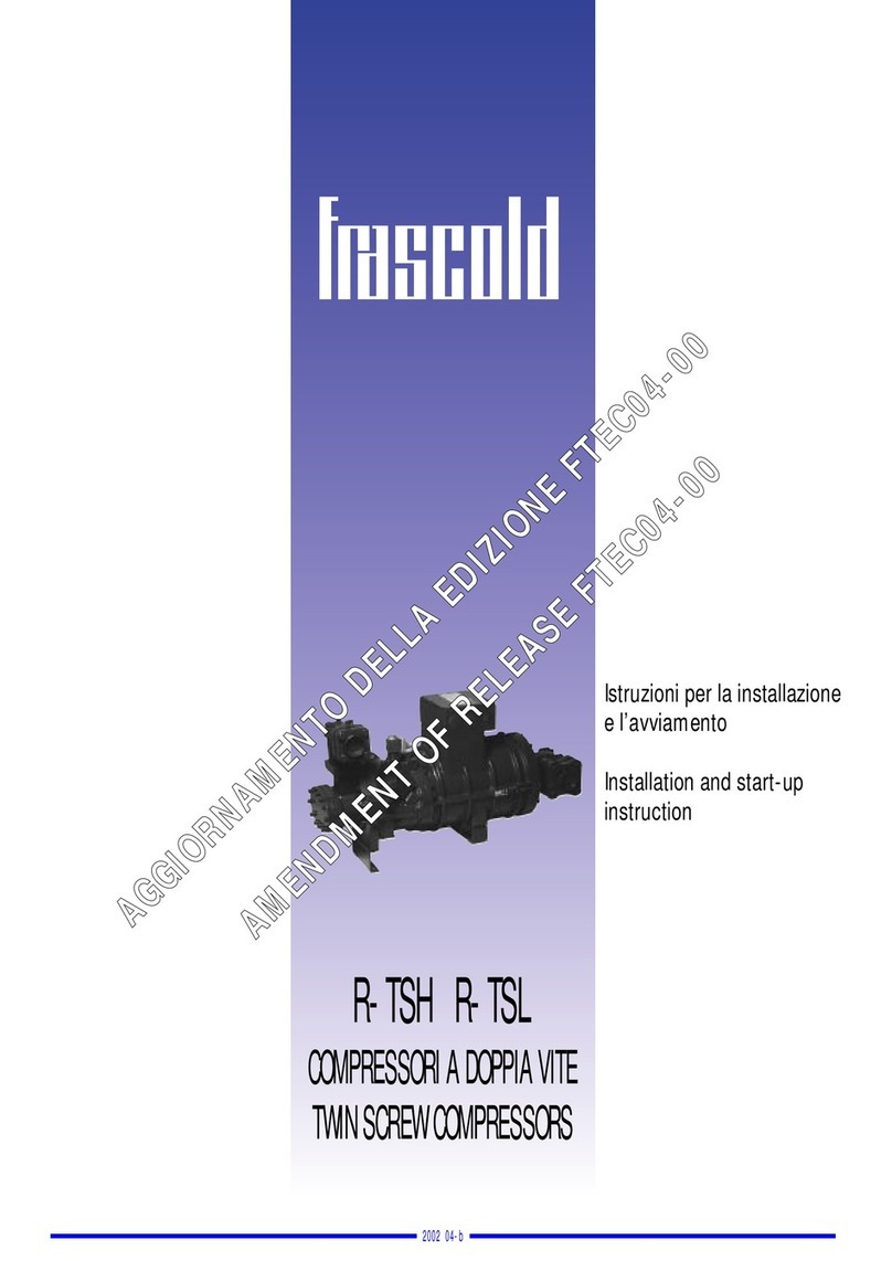
RFC SL Series User manual

SL series screw refrigeration compressor
technical manual
Zhejiang Daming Refrigeration Technology Co., Ltd.

Table of contents
1. Summary 01
1.1 Product introduction 01
1.2 model name 01
1.3 Product Series 01
1.4 Introduction 02
1.5 design specification 02
1.6 Operating Range Chart 03
2. Refrigerated Oil Management 05
2.1 The role of refrigeration oil in the press knitting machine 05
2.2 S1 compressor specified refrigeration oil 05
2.3 Refrigerant oil replacement requirements 05
2.4 External oil circuit system 06
3. Start, stop and capacity control 06
3.1 Cooling capacity control06
3.2 Efficiency at Partial Load and Considerations07
3.3 Compressor start and stop 07
4. Electrical articles 08
4.1 motor08
4.2 protective device 09

4.3 Power supply 10
4.4 Electrical accessories selection 10
5. Main accessories and accessories 11
5.1 Suction filter 11
5.2 one-way valve 11
5.3 Rubber damping pad 11
5.4 Accessories in the oil circulation circuit 12
6. Outline 15
6.1 RFC1 series outline drawing 15
6.2 RFC2 series outline drawing 16
6.3 RFC3 series outline drawing 17
6.4 RFC4 series outline drawing 18
6.5 RFC5 series outline drawing 19
7. system applications 20
7.1 Overview 20
7.2 general principles 20
7.3 External oil circuit system 22
7.4 Economizer Configuration Requirements 23
7.5 Condensing pressure regulation 24
7.6 Parallel system operation requirements 24

8. Install and run 25
8.1 Install 25
8.2 run 25
9 Failure analysis and maintenance 27
9.1 General fault description 27
9.2 maintenance 28
9.3 Maintenance points 28

1. Summary
1. 1 Product introduction:
SLG&SLD series products are low-temperature special screw refrigeration compressors
carefully developed by RFC in recent years to integrate low-temperature refrigeration market
applications and customer needs, and learn from the experience of domestic and foreign
counterparts. The product is designed with excellent performance, simple structure and
convenient use. It focuses on the application needs of the low temperature market and is
widely used in agriculture, fishing, meat, food industry, process cooling, freeze drying and
other industries.
There are 32 models of SLG&SLD semi-hermetic screw compressors. SL series
compressors from 30HP to 300HP (displacement volume at 50Hz: 102, 128, 145, 158, 188,
205, 235, 248, 293, 354, 416, 520, 641, 812, 908, 1006m³ /h), each type of compressor has
two different built-in volume ratios, which are suitable for occasions with low evaporating
temperature and medium and high evaporating temperature respectively. Therefore, the user
can choose the ideal compressor according to the actual application, so as to obtain the best
compression efficiency.
SL series compressors all use external oil separators. The use of external oil separators
can provide greater flexibility in design and structural arrangement. In the parallel combination
system of multiple compressors (from 2 to 6 units) ) can only use a common oil separator. In
addition, the use of oil cooling has broadened the compressor application limits so that it can
operate under harsh operating conditions.
A complete set of accessories required for the oil return line (from the oil separator to the
compressor) is available as standard. In addition all matching oil separators and oil coolers are
also available.
Due to the minimal vibration and no exhaust pulsation, the use of shock absorbers and
flexible nozzles is not necessary. Plus, the lower noise concentrated in the mid-to-high
frequencies is very easy to isolate.
The characteristics of SL series compressors are: the oil-injected twin-screw design is
adopted, the male rotor is directly connected to the motor (2 poles, about 2960 rpm), and the
perfect rotational motion makes it run extremely smoothly. The rotor profile is asymmetrically
designed (the number of teeth of the male rotor is 5, and the number of teeth of the female
rotor is 6). .
Oil pressure driven spool valve cooling capacity control enables the compressor to have
high compression efficiency under partial load, making SL series compressors especially
suitable for those occasions that need to work under partial load for a long time.
The cycle efficiency (COP) can be further achieved by using an economizer (ECO) cycle
that increases the refrigerant liquid subcooling

1.2 model nomenclature
S Semi-hermetic
L Refrigeration
D D: low temperature G: high temperature
210 Displacement (m3/h)
60 Motor nominal power (HP)
Y Step adjustment (Step Control)
D Single stage compression (single stage)
1 Version
Refrigeration Displacement (m3/h)
S L D 210 -60 Y D 1
Semi-hermetic low temperature Motor nominal power (HP)
Compressor rated power: 380V-3-50HZ, if customers need other special voltage and
frequency, please contact RFC.
1.3 Product Series
SL series compressor displacement specification table
Figure 1-A SL series compressor displacement specification table

1.4 Introduction
The rotors are located in a horizontally arranged compression chamber with a suction port
(on the motor side) and a discharge port, with extremely small gaps between the rotors and
between the rotors and the housing by means of direct injection onto the rotor profile. The oil
film formed by the lubricating oil performs dynamic sealing. The formation of the compression
process is that the motor drives the rotor to rotate, causing the volume to gradually decrease;
the multiple compression chambers formed between the rotor and the casing due to the
rotation of the rotor move along the axial direction of the rotor while the volume gradually
decreases. Small.
The basic process of compression can be divided into three stages: suction,
compression and exhaust
Figure 1-B Compression principle of screw compressor

1.5 design specification
model
Exhaust
volume
50Hz
Motor
nominal
power
Weight
exhaust
pipe
diameter
Suction
pipe
diameter
ability
adjustm
ent
protection
module
Standar
d Motor
star/delta
starting
current
Maximu
m
operating
current
m'/h Hp/Kw Kg mm mm A A
SLD100-25 102 30/22 245
45 57
50% ,
70% ,
100
adjust INT 69
380V/3/
50Hz-
460V/
3/60HZ
131 42
SLG100-35 40/30 255 134 56
SLD120-30 128 30/22 245 131 42
SLG120-40 40/30 255 134 56
SLD140-40 145 40/30 255 134 63
SLG140-50 50/37 275 139 78
SLD160-50 158 50/37 260 179 75
SLG160-60 60/45 280 182 85
SLD190-50 188 60/45 405
57 76
182 90
SLG190-65 70/52 430 193 104
SLD210-60 205 60/45 410 182 95
SLG210-70 70/52 440 195 108
SLD230-70 235 70/52 420 193 112
SLG230-80 80/60 450 298 126
SLD250-75 248 75/57 430 230 118
SLG250-90 90/68 460 318 144
SLD290-80 293 80/60 535
67 89
298 126
SLG290-100 100/75 570 338 158
SLD350-100 354 100/75 545 338 157
SLG350-120 120/89 590 366 187
SLD420-125 416 120/89 670 76 89 416 187
SLG420-150 145/108 690 453 228
SLD520-160 520 160/120 1030
89 108
25% ,
50% ,
75%,
100
543 251
SLG520-180 180/135 1060 595 284
SLD640-200
641
200/143 1050 678 301
SLG640-220 210/157 1090 767 331
Note: Please confirm the rated current of the compressor under the design conditions
according to the RFC selection procedure, and confirm the maximum operating current value
according to the limit conditions to select the contactor, power cord and fuse protection
components。

1. 6 Operating Range Chart
SLD series R22
Evaporation temperature °C
SLG series R22
Evaporation temperature °C
Condensin
g
tem
p
erature°C Condensingtemperature°C

SLD series R404A/R507
Evaporation temperature °C
SLD series R404A/R507
Evaporation temperature °C
Condensing temperature°CCondensing temperature °C

2. Refrigerated oil management
2.1 The role of refrigeration oil in compressors
In SL series compressors, refrigeration oil has the following functions:
a. An oil film is formed between adjacent compression cavities and between the
compression cavities and the shell to reduce the leakage of refrigerant gas during the
compression process and improve the compressor efficiency.
b. An oil film is formed in the bearing to ensure the normal operation of the bearing.
c. Absorb and take away the compression heat generated by the refrigerant gas during
the compression process and the friction heat generated by the bearing during the mechanical
movement, so as to reduce the compressor discharge temperature.
d. Control of cooling capacity regulating slide valve.
2.2 SL compressor specified refrigeration oil
The refrigerant R22 R404A/R507
Refrigeration Oils
( Refrigeration Lubricant) 6100 (AB100) 6170 (POE170)
Density 0.868 0.98
Flash Point 196 170
Table 2-1 Technical parameters of refrigeration oil ( Refrigeration Lubricant)
Note:
1) RFC only recognizes specified refrigeration oil;
2) The minimum starting oil temperature of the compressor is 30;
3) 6100 ( this item No is from company's order system), equals to AB100 refrigeration oil ( Refrigeration Lubricant);
4) 6170 ( this item No is from company's order system), equals to POE170 refrigeration oil ( Refrigeration Lubricant);
5) The detailed parameters of refrigeration oil ( Refrigeration Lubricant) on the Table 2-1 will vary with different
brands of refrigerants and lubricants

2.3 Refrigerant oil replacement requirements
When filling the compressor with refrigeration oil, ensure that the system is clean. After
the system runs for 2000 hours for the first time, it is recommended to replace the refrigeration
oil again to ensure the long-term normal operation of the compressor.
Lubricating oil can easily absorb moisture in the air, so long-term exposure of lubricating
oil to the air should be avoided;
To ensure that the water content in the system is kept to a minimum, it is recommended
that the system be heated and evacuated for as long as possible after the system is replaced
with new oil;
Lubricating oil pollution will cause oil circuit blockage, so the external oil circuit system
must be installed with an oil filter, and a differential pressure switch must be installed before
and after the filter. When the differential pressure reaches the set value (1.5Bar), the oil filter
must be replaced;
The compressor runs at a high discharge temperature (95~110) for a long time, which is
easy to accelerate the deterioration rate of the lubricating oil. Please check the performance of
the lubricating oil regularly and shorten the oil change interval appropriately;
The acidification of the lubricating oil will directly affect the life of the motor. When the PH
of the lubricating oil is less than 6, it is recommended to replace the oil and accessories such
as the filter drier. If the compressor motor burns, it will produce acidic harmful substances and
burnt debris, which will be brought into the system together. During processing, the oil filter
element and lubricating oil must be replaced several times until the cleanliness and acidity of
the oil circuit meet the requirements.
warn:
IfitisfoundthatthecustomerdoesnotusethelubricatingoilspecifiedbyRFC,

2. 4 External oil circuit system
The SL compressor needs to be equipped with an oil cooler, and the heat exchange of the oil
cooler is obtained according to the RFC selection procedure. RFC requires that the design
pressure drop of the external oil circuit system pipeline is not more than 1bar, so as not to
affect the normal lubrication of the compressor.
The external oil circuit components are as follows:
serial
number Part Number describe quantity
1 5119892 Adapter 2
2 6180345 Oil flow switch FYL-08 1
3 6191090 Teflon gasket 4
4 6114474 Active joint 1"-14UNS welding end
D=16 4
5 7100357 Oil Filter FOF-5/8" 1
6 6120210 Aluminum spacer OD.50xlD.42x1.5 2
7 6180335 Solenoid valve 032F1228 1
8 5103330 Solenoid valve coil 230V50/60HZ 1
9 5181250 Motor protection module INT69VS
230V 1
10 6140635 Oil sight glass 5/8" 1
11 6180334 capacitance 1
External oil circuit diagram

3. Start, stop and cooling capacity control
3.1 Cooling capacity control
3.1.1 SL100~420 compressors adopt three-stage energy regulation, the minimum load is 50%,
and its control solenoid valve logic is as follows:
compressor load 50% solenoid valve 75% solenoid valve
Minimum load (start) power ups power outage
70% load power outage power ups
100% load power outage power outage
Table 2-2
3.1.2 SL520~640 compressors use four-stage energy regulation, the minimum load is 25%,
and the minimum load is only used for startup. The logic of its control solenoid valve is as
follows:
compressor load 25% solenoid valve 50% solenoid valve 75% solenoid valve
Minimum load (start) power ups power outage power outage
50% load power outage power ups power outage
75% load power outage power outage power ups
100% load power outage power outage power outage
Notice:
1) Careful and extensive testing is strongly recommended for less than 50% load conditions.
Continuous operation below 50% load should be avoided unless adequate measures are
taken to prevent:
Poor oil return due to low return air flow rate.
Excessive exhaust temperature due to poor motor cooling and reduced efficiency
(especially at high pressure ratios)
Motor overheating due to low power factor at low loads (especially when supply voltage
exceeds rated voltage)
2) Since the cooling of the motor may not be guaranteed at the 25% minimum cooling capacity
level, the minimum cooling capacity level can only be used for the start and stop phases of the
compressor.

Suggest:
To avoid overheating of the motor, the operating time below 50% of the cooling capacity
should not exceed 5 minutes.
Do not drop the compressor directly from full load to minimum load. If unloading is
necessary, the compressor should run for at least 3 minutes at 50% load regulation. When the
compressor load is suddenly reduced to the minimum cooling capacity, a large amount of
refrigerant may return to the compressor, causing liquid slam; if the energy regulation of the
compressor is out of sync with the actual load change, please check and set the control
parameters again.
3.2 Efficiency at Partial Load and Considerations:
In order for the compressor to have high efficiency at part load, the size and shape of the axial
and radial discharge ports have been optimized in the design.
When the compressor works at part load, the discharge temperature will rise (mandatory
measures should be taken to control the discharge temperature within the specified range),
and its efficiency is slightly lower than that at full load.
The exhaust temperature will rise rapidly if:
Condensing pressure rises;
evaporative pressure drop;
Suction superheat rises.
3.3 Compressor start and stop
It is recommended that the compressor run at the minimum load cooling capacity level for at
least approximately 25 seconds during startup and shutdown.
The sequence of starting and stopping is shown in Figure 3-1, which is suitable for all
stage-adjusted screw compressors; meanwhile, noise caused by temporary reversal caused
by the backflow of a large amount of refrigerant during shutdown can be avoided.
Figure 3-1 Control requirements for compressor startup and shutdown

Requirement:
In order to ensure that the compressor starts with the minimum load and consider the safety of
the compressor, the compressor should control the start and stop of the compressor according
to the requirements of the above figure 3-1
4. Electrical articles
4.1 motor
4.1.1 Overview
In order to reduce the starting current, the SL compressor motor adopts the star-delta
starting method.
The standard motor of SL series compressors is a 3-phase asynchronous 2-stage Y/
△
winding type (rotation speed is 2950r/min at 50Hz), and the applicable voltage is 380V/3/50HZ
or 460V/3/60HZ. If you need other special electrical system, please contact RFC.
The operating current and input electric power under different working conditions can be
calculated by the Lefkang selection software. The main electrical parameters such as star
Y/
△
structure Star structure Triangular structure
Figure 4-1 Internal structure of Y/motor
In order to reduce the resistance torque at start-up to avoid overloading the motor at
start-up, the compressor should start at minimum load.
In Figures 4-2 and 4-3, the three-phase electrical wiring diagram of the Y/
△
motor and
the time sequence diagram of the contactor closing are given. The compressor should be set
as follows during the startup process:

Figure 4-2 Three-phase electrical wiring diagram of Y/△ motor
*For star-delta motors, the start-up time of star (closing contactors K1 and K3) should not
exceed 1.5 seconds (0.8~1 second recommended); on the other hand, when switching to delta
operation (closing contactors K1 and K2) ), when the K3 contactor is disconnected, the K2
contactor must be closed within a delay of 35~50 milliseconds:
*For partial winding motors, within 1 second of closing the start contactor K1 (0.6 seconds
recommended), then close the running contactor K2
4.2 protective device
4.2.1 Motor thermistor
There are 6 PTC thermistors linked in series buried in the motor windings to prevent the
motor from burning out due to high temperature. The three thermistors are set at the suction
end of the motor, and the cut-off temperature is 100°C, and the other three are set at the other
end of the motor, and the cut-off temperature is 120°C.
The cold resistance value of the thermistor chain (below 40°C) must be less than 1800Ω:
if any one of the thermistors reaches the critical temperature, the resistance value of the
resistance chain increases exponentially, and the electronic protection module SE-E will action,
cut off the power supply. The resistance value can be measured between the T1 and T2
terminals located on the terminal block.
Note: When measuring the resistance of the thermistor, the measurement voltage
should not be higher than 3V.
4.2.2 protection module
The protection module INT 69 is supplied as a standard accessory with the following

functions:
1) Monitor motor and exhaust temperature;
2) Monitor the rotation direction of the motor;
3) Monitor the power supply for phase loss;
Figure 4-3 Protection module wiring diagram
4.2.2.1 temperature monitoring
Motor temperature and exhaust gas temperature are monitored by PTC sensors. The
exhaust gas temperature sensor is installed near the exhaust shut-off valve. This sensor is
connected in series with the motor thermistor. The reset of the controls is automatically reset
after an alarm and requires a power disconnection of at least 2 seconds.
Note: Before restarting the compressor after an alarm, the operator must carefully check the
motor and discharge temperature, and confirm that the PTC resistor chain resistance value is
less than 3KQ.
4.2.2.2 Phase loss monitoring
The phase loss signal is monitored not only when the compressor is started, but during
the entire operation of the compressor. If a phase loss is detected, the power supply to the
compressor will be cut off within 1.5 seconds. Then every 5 minutes, the compressor will
automatically restart. However, if there are 3 consecutive phase loss within 30 minutes or 10
consecutive phase loss within 24 hours, the electronic protection module will be locked and
can only be reset manually and needs to be disconnected from the power supply for at least 2
seconds.

Normally, the INT 69 module is installed in the junction box of the compressor. However, in the
following cases, the module can also be installed in the main control box away from the
compressor, but the following points should be noted:
1) The connecting cables to the motor terminals should be carefully checked and
connected in the specified phase sequence:
L1 is connected to terminal 1; L2 is connected to terminal 2; L3 is connected to terminal 3;
the motor rotation direction is monitored with a phase monitor.
2) The connection between INT 69 module and PTC sensor should use shielded cable or
paired stranded wire alone to prevent magnetic field induction.
3) Add an additional 4A fast blow fuse between the protection module "L1/L2/L3" terminal
and the motor terminal 1/2/3.
4.2.3 Oil flow switch
The oil flow switch is installed in the oil circulation circuit between the oil separator and
the compressor, and is used to timely monitor whether the lubricating oil circulation is normal.
4.3 Power supply
Power Requirements:
Standard motor power supply: 380V-3-50Hz/460V-3-60Hz (other power supplies can be
customized according to customer requirements);
Allowable voltage range: within ±10% of the rated voltage for instantaneous operation;
Long-term operation within ±5% of rated voltage;
Allowable voltage unbalance between L1-L2-L3: ±2%;
Maximum voltage drop during startup: 10% of rated voltage;
Allowable frequency range: rated frequency ±2%;
Allowable current unbalance: <5% (R-S-TH phase unbalance current)
<12%(unbalanced current between six terminals 1-2-3-7-8-9)
Current unbalance calculation:
Proceed as follows:
First contactor current I1-I2-I3
Second contactor current I7-I8-I9
Each phase supply current:

IR=I1+I7
IS=I2+I8
IT=I3+I9
R-S-T three-phase unbalanced current:
IW=(IR+Is+IT)/3
SB%=Max((IR, Is, IT)-IM)/IM ×100%
SB%<5%
1-2-3-7-8-9 Unbalanced current among six terminals:
IM=(I1+ I2+ I3+ I7+ I8+ I9)/6
SB%=Max((I1, I2, I3, I7, I8, I9)-IM)/IM ×100%
SB%<12%
4. 4 Electrical accessories selection
he size of cables, fuses and contactors should be selected according to the maximum working
current (FLA) of the motor under normal operating conditions.
When using a star-delta winding motor, the size of the delta and main contactors must be
at least 75% of the maximum operating current (FLA), and the size of the star contactor must
be at least 40% of the maximum operating current (FLA).
5. Main accessories and accessories
5.1 Suction filter
The compressor is equipped with a suction filter, which can be inspected and cleaned
after disassembling the suction shut-off valve (or suction side end cover) (Figure 5-
A
)
one-way valve
Figure 5-A Suction Filter and Check Valve Location
This manual suits for next models
26
Table of contents