RFL 3000 ES42H User manual

RFL 3000 –ES42H Ethernet Edge Switch Installation & User Guide (5/06)
RFL 3000 ES42H Ethernet Edge Switch
Installation and User Guide
May, 2006

RFL 3000 –ES42H Ethernet Edge Switch Installation & User Guide (5/06)

RFL 3000 –ES42H Ethernet Edge Switch Installation & User Guide (5/06)
RFL 3000 ES42H Series Edge Switch
Installation and User Guide
Trademarks
Ethernet is a trademark of Xerox Corporation
NEBS is a trademark of Telcordia Technologies
UL is a registered trademark of Underwriters Laboratories
Important: The RFL 3000 ES42-Series 10/100 Mb/s Edge Switches contains no
user serviceable parts. Attempted service by unauthorized personnel shall render
all warranties null and void. If problems are experienced with RFL 3000 ES42
10/100 Mb/s Edge Switch products, consult Section 5, Troubleshooting, of this
User Guide.
Copyright ©2005 RFL Electronics Inc. All rights reserved. No part of this publication
may be reproduced without prior written permission from RFL Electronics Inc.
Printed in the United States of America.
Federal Communications Commission
Radio Frequency Interference Statement
This equipment generates, uses and can radiate frequency energy and if not
installed and used properly, that is in strict accordance with the manufacturer's
instructions, may cause interference to radio communication. It has been tested and
found to comply with the limits for a Class A computing device in accordance with the
specifications in Subpart J of Part 15 of FCC rules, which are designed to provide
reasonable protection against such interference when operated in a commercial
environment. Operation of this equipment in a residential area is likely to cause
interference, in which case the user, at his own expense, will be required to take whatever
measures may be required to correct the interference.
Contacting RFL Electronics Inc.
Please use the mailing address, phone and fax numbers and email address listed below:
RFL Electronics Inc.
353 Powerville Road
Boonton TWP, NJ 07005-9151
Phone (973) 334-3100
Fax (973) 334-3863
Website: http://www.rflelect.com
i

RFL 3000 –ES42H Ethernet Edge Switch Installation & User Guide (5/06)
TABLE OF CONTENTS
SECTION 1 SPECIFICATIONS................................................................................................. 1
1.1 Technical Specifications................................................................................................................. 1
1.2 Summary of models and descriptions:............................................................................................ 4
SECTION 2 INTRODUCTION................................................................................................... 5
2.1 Inspecting the Package and the Product ......................................................................................... 5
2.2 Product Description........................................................................................................................ 5
2.3 Frame Buffering and Latency......................................................................................................... 7
2.4 Features and Benefits...................................................................................................................... 8
2.5 Applications for RFL 3000 ES42H Series Edge Switches............................................................. 9
SECTION 3 INSTALLATION .................................................................................................. 12
3.1 Locating the Edge Switch Unit..................................................................................................... 12
3.2 MC14-TRAY for Rack Mounting of RFL 3000 ES42H Series Switches................................... 12
3.3 MC14-TR+PS9 and MC14-TR+PS9X2 for Rack Mounting Media Edges.................................. 13
3.4 DIN-Rail mounting option............................................................................................................ 14
3.5 Power Requirements, Power Supply Types for RFL 3000 ES42H Series Switches .................... 14
3.6 Powering the RFL 3000 ES42H (DC internal) with 12V, 24V or –48VDC power input............. 15
3.7 RFL 3000 ES42H DC-powered, 12VDC, 24VDC and -48VDC Installation............................... 16
3.8 Connecting Ethernet Media.......................................................................................................... 17
3.8.1 Connecting Twisted Pair (RJ-45, CAT 3 or CAT 5, Unshielded or Shielded)..................... 17
3.8.2 Connecting Fiber Optic ST-type, “twist-lock” ..................................................................... 17
3.8.3 Connecting Fiber Optic SC-type, "Snap-In"......................................................................... 18
3.8.4 Connecting Single-Mode Fiber Optic................................................................................... 18
3.8.5 Power Budget Calculations for RFL 3000 ES42H Series, Fiber Media............................... 18
3.8.6 Connections to NICs which support Auto-Negotiation, RJ-45 ports.................................... 19
SECTION 4 OPERATION ....................................................................................................... 20
4.1 Dual-Speed Functionality, and Switching.................................................................................... 20
4.2 Auto-cross (MDIX), Auto-negotiation and Speed-sensing........................................................... 20
4.3 Dual LEDs, Front-panel and side-panel (RFL 3000 ES42 Series) ............................................. 21
4.4 Hardware operated Alarm Contact for monitoring internal power supply................................... 21
SECTION 5 TROUBLESHOOTING........................................................................................ 23
5.1 Before Calling for Assistance....................................................................................................... 23
5.2 When Calling for Assistance........................................................................................................ 24
5.3 Return Material Authorization (RMA) Procedure........................................................................ 24
5.4 Shipping and Packaging Information ........................................................................................... 25
APPENDIX A: WARRANTY INFORMATION.............................................................................. 26
ii

RFL 3000 –ES42H Ethernet Edge Switch Installation & User Guide (5/06)
SECTION 1 SPECIFICATIONS
1.1 Technical Specifications
Ports Performance
When a port is operating at 100Mbps:
Data Rate: 100Mbps
When a port is operating at 10 Mbps:
Data Rate: 10 Mbps
Network Standards
100Mb: Ethernet IEEE 802.3u, 100BASE-TX, 100BASE-FX
10 Mb: Ethernet IEEE 802.3, 10BASE-T
Auto-sensing for speed: IEEE 802.3u
Packet-Processing Between Domains
Filter and Forward Rate from 100Mbps ports: 148,800 pps max
Filtering and Forwarding Rate from 10 Mbps ports: 14,880 pps max.
Processing type: Store and Forward, non-blocking
Auto-learning: 2K address table
Address buffer age-out time: 300 sec.
Packet buffers memory: 128KB, dynamically shared on all domains
Latency (not including packet time): 100 to 10 Mbps: 5μs
10 to 100Mbps: 15μs
Path Delay Value: 50 BT on all ports
LLL(Link-Loss-Learn): Factory default is activated on port 1 and 2 (allow
to flush the internal address buffer , and qualify to use with S-Ring and RSTP for
faster recovery in ring topology)
Maximum Ethernet Segment (or Domain) Lengths
10BASE-T (Unshielded twisted pair) - 100 m (328 ft)
100BASE-TX (CAT 5 UTP) - 100 m (328 ft)
100BASE-FX, half-duplex: (multi-mode) - 412 m (1350 ft)
100BASE-FX, full-duplex: (multi-mode) - 2 km (6,562 ft)
100BASE-FX, half-duplex: (single-mode) - 412 m (1350 ft)
100BASE-FX, full-duplex: (single-mode) - 20 km (65,620 ft)
100BASE-FX, full-duplex: (single-mode, long reach) - 40 km (131,240 ft)
Operating Environment
ES42H: -13ºF to 140ºF (-25ºC to 60ºC) Long term per agency tests (UL).
-40ºF to 149ºF (-40ºC to 85ºC) Short term per IEC Type tests.
Storage Temperature,
All models: -40ºF to 160ºF (-40ºC to 85ºC)
Cold Start: -20ºC
Ambient Relative Humidity: 5% to 95% (non-condensing)
Altitude (All models): -200 to 5000ft. (-60 – 15,000 m)
1

RFL 3000 –ES42H Ethernet Edge Switch Installation & User Guide (5/06)
Conformal Coating (optional) for humidity protection
Note: The RFL 3000 ES42H is designed for NEBS compliance, including, vibration,
shock and altitude.
Packaging:
Enclosure: Rugged sheet metal (Steel).
Dimensions of the Switch unit:
3.7 in
H x 3.0 in W x 1.7 in D (9.4 cm x 7.6 cm x 4.3 cm)
Weight: all models: 13 oz. (370g);
Power supply, –d, and i: 5.8 oz (165g)
–Hd, and Hi: 5.8 oz (165g)
–Pd, and -Pi: 7.9 oz (225g)
Cooling Method:
Convection on the office model. The RFL 3000 ES42H models have closed cases to
withstand dirt and use special thermal techniques to transfer heat to the outside of the
case for cooling.
ALARM RELAY Terminal Block, H and P models only, two screw terminals:
Internal 60VA relay contact: Open for power Off, closed for power On (Hardware).
POWER SUPPLY
The RFL 3000 ES42H products are intended to be supplied by a Listed, Direct Plug-In
power unit, marked “Class 2”, or a Listed ITE Power Supply, marked “LPS”, which has
suitably rated output voltage (i.e. 9vdc, 12vdc, 24vdc, 48vdc), and suitably rated output
current (i.e. 100mA to 500mA).When connected to a 48V centralized DC source, these
products shall be provided with a Listed 5 A DC fuse in the supply circuit.
AC POWER SUPPLY ( using an external power adapter):
All models have an (8-15)VDC output with 6ft long cord and a 2.5mm center +ve jack.
The external AC power supplies are temperature rated to match the Edge Switch ratings.
International (-i) models. Input: 240vac at 50Hz with IEC 320 connector for the user
supplied AC power cord.
Output:12vdc, 1Amps
Factory Floor Models (H) Ratings (-25 to 60°C)
North America (-Hd) models. Hardened, factory floor temperature rated. Input: 6ft AC
3power cord to IEC 320 connector on the 100-240vac 47-63Hz external power adapter.
Output:12vdc, 1.25Amps
International (-Hi) models. Factory floor temperature rated. Input: IEC 320 connector
on the 100-240vac 47-63Hz external power adapter. Requires a user supplied power cord
Output:12vdc, 1.25Amps.
Output:12vdc, 2Amps.
2

RFL 3000 –ES42H Ethernet Edge Switch Installation & User Guide (5/06)
Direct DC POWER SUPPLY : built-in terminal
block for +, -, ground along with 12VDC jack
12V DC internal (range 8.0 to 15V DC),
24V DC internal (range 10 to 36V DC),
-48V DC internal (range 30 to 60V DC),+ , -, ground.
Note: DUAL-SRC-24KIT- For RFL 3000 ES42H-24VDC unit only (sold separately).
See 3.6.
Power Consumption: See Section 3.6.
Note 1: the 12V DC jack can be used for dual source DC input using an AC adapter and
the DC terminal block. Power supply protection is provided by internal diodes.
Note 2: The Direct DC power floats. The user may ground either “+” or “-” if desired.
Power Consumption, all models: 7.0 watts typical, 9 watts max.
Port Connectors:
RJ-45 Ports: support 100BASE-TX and 10BASE-T with auto-cross (MDIX).
They are shielded 8-pin female connectors for shielded (STP) and unshielded
(UTP) Cat 3, 4, 5 cable.
One Fiber optic port: On the RFL 3000 ES42H Series it is 100Base-FX with a
“fiber flavor” choice of multimode SC, ST, LC or MTRJ or single mode SSC,
SSCL, SST or SLC connectors. (By default factory settings is at “Full” duplex on
fiber ports)
LED Indicators (Front)
POWER: Steady ON when power applied
10/100: Steady ON for 100Mbps; OFF for 10 Mbps(copper ports only)
LK/ACT: Steady ON for LINK (LK) with no traffic, BLINKING indicates
port is transmitting / receiving (ACT).
F/H: Steady ON for full-duplex, OFF for half-duplex (Fiber port only)
Mounting options
Metal mounting clips for panel mounting: included
DIN-Rail mounting option: Model # DIN-RAIL MC2 (see Section 3.4)
Rack-mount option: MC14-TRAY
Depth: 6.0”, width: 17” Height: 2.25” (15cm D x 43cm W x 5.7cm H)
Mean Time Between Failure (MTBF) – over15 years, Telcordia (Bellcore) Method
3

RFL 3000 –ES42H Ethernet Edge Switch Installation & User Guide (5/06)
Agency Approvals and Standards Compliance:
UL Listed (UL 60950), cUL, CE, Emissions meets FCC Part 15 Class A.
NEBS L3 and ETSI compliant.
H models: IEEE P1613 Env. Std for Electric Power Substations
IEC61850 EMC and Operating Conditions Class C Power Substations
Warranty: Three years, return to factory, Made in USA
1.2 Summary of models and descriptions:
Note: The RFL 3000 ES42H model # consists of the base unit type and the power input.
Insert S for sgl-mode , the fiber flavor (2ff) and the power input. H- hardened,
R- Din –Rail MC2, d- domestic, i – international power type.
The “2ff” field is for selection of the desired “fiber flavor” as listed below. The 1ff (one
fiber +five RJ-45 ports) and no ff (six RJ-45 ports only)models are also same as below,
except the port options.
RFL 3000 ES42 Models (four RJ-45 10/100 with two100Mb fiber flavor option).
ES42H-2ff-Hd, Hi = Hardened (H), four RJ-45+ two 100Mb Fiber port for factory floor
(-25 to 60C) using a direct DC ( 8-15VDC) and/or external AC hardened power
supply (included).
ES42H-2ff-12VDC = Same as ES42H model, except AC hardened power supply is not included
ES42H-2ff-24VDC = Same as ES42H-12VDC model, except 24VDC power input replaces 12VDC.
ES42HR-2ff-24VDC = Same as ES42H-24VDC model, but includes DIN-RAIL-MC2 mounting
ES42H-2ff-48VDC = Same as ES42H-24VDC model, except -48VDC power input replaces 24VDC.
Note: For dual source 24V power input to DC jack, order Model# DUAL-SRC-
24Kit
“SC” = 100Base-FX-SC: multi-mode fiber optic with SC type connector, 2km.
“SSC”= 100Base-FX-SSC: single-mode fiber optic with SC type connector, 20km.
“SSCL”= 100Base-FX-SSCL: single-mode fiber optic with SC type connector, 40km.
“ST” = 100Base-FX-ST: multi-mode fiber optic with ST type connector, 2km.
“SST” = 100Base-FX-ST: single-mode fiber optic with ST type connector, 20km.
“SLC”= 100Base-FX-SLC: single-mode fiber optic with LC type connector, 15km.
“MTRJ”= 100Base-FX-MTRJ: multi-mode fiber optic with MTRJ type connector, 2km.
“SLC”= 100Base-FX-SLC: single-mode fiber optic with LC type connector, 15km.
“SFC”= 100Base-FX-SFC: single-mode fiber optic with FC Screw type connector, 20km.
“SSCX”= 100Base-FX-SSCX: single-mode fiber optic with SC type connector, 100km.
Accessories
MC14-TRAY = 19” Rack-mount tray for 14-series Switch models, up to 16 units
Other Tray configurations with power supplies and power cabling included -
See Section 3.3
DUAL-SRC-24KIT= Cable kit for 24VDC input power input jack for one RFL 3000
ES42, any 24VDC model
DIN-RAIL-MC2 = Metal DIN-Rail mounting bracket for one RFL 3000 ES42 Series
Switch, See Section 3.4
Conformal Coating (for high humidity and “tropical” applications) - request quote.
4

RFL 3000 –ES42H Ethernet Edge Switch Installation & User Guide (5/06)
SECTION 2 INTRODUCTION
This section describes RFL 3000 ES42 Series models, including appearance,
features and typical applications.
2.1 Inspecting the Package and the Product
Examine the shipping container for obvious damage prior to installing this
product; notify the carrier immediately of any damage which you believe occurred during
shipment or delivery. Inspect the contents of this package for any signs of damage and
ensure that the items listed below are included.
This package should contain:
1 RFL 3000 ES42Series Edge Switch unit,
1 External Power Supply, (for -d, -i, -Hd, -Hi, -Pd and -Pi models only)
1 (set) Metal panel mounting clips and screws (2 each)
1 User Guide (this manual)
Remove the RFL 3000 ES42 Series Edge Switch from the shipping container. Be
sure to keep the shipping container should you need to ship the unit at a later date. In the
event there are items missing or damaged contact your supplier. If you need to return the
unit use the original shipping container. Refer to Section 5 Troubleshooting, for specific
return procedures.
2.2 Product Description
RFL 3000 ES42 Series Switches are designed as an Ethernet edge solution in
heavy-duty industrial, military and un-controlled temperature applications, as well as an
economical solution for the growing requirements of managed networks. RFL 3000
ES42, a six port versatile family of compact Edge switches, loaded with factory
configurable fiber options and AC/DC power input options with Alarm terminal block
and innovative packaging is ready to serve the needs of edge-of-the network applications.
The RFL 3000 ES42 family of Edge Switches have a wide breadth of port
configurability and fiber port type options - six 10/100 copper ports or four 10/100
copper ports and two 100 Mb Fiber port or five copper ports with one 100Mb Fiber port
built in, covers the full range of application environments, Hardened (factory floor and
substations). Extra features for heavy-duty and extended temperature operation ranges are
included selectively in the Hardened model. The breadth of models and flavor of fiber
port types offers the best price-to-value ratio for each user and installation. The compact
package is ideal for network edge installations, and is able to be conveniently Din rail
mounted to suit any application.
The RFL 3000 Edge switches include Link-Loss-Learn(LLL) feature (factory
configurable on ports 1 and 2 to qualify for any redundant and self-healing managed
network structures. The Link-Loss-Feature in RFL 3000 ES42H allows the Edge switches
5

RFL 3000 –ES42H Ethernet Edge Switch Installation & User Guide (5/06)
to flush the internal address buffers in milliseconds to permit a quick change in LAN
packets flow, and pass the reconfiguration signal down the line to other ring switches in
the redundant structure for faster recovery. RFL 3000 Edge switches, combined with
other RFL 3000 managed switches, running STP/RSTP or S-Ring, can often provide high
availability Redundant LANs at economical cost.
A robust metal case with convection cooling is featured. Metal mounting clips are
included, and rack-mount tray options are available.
The RFL 3000 ES42H Hardened units are for substation and factory floor applications.
The RFL 3000 ES42HH models are built with high-grade components and are
constructed using special thermal techniques and a metal case for heavy duty industrial
jobs. In addition to a Hardened AC power option and jack, terminals for internal DC
power choices at 8 to15V, 24V or -48V DC are included. The ambient temperature rating
of –25 to 60C is for industrial use. No internal air flow is required for cooling, so it resists
dust, dirt, moisture, smoke and insects. Mounting options include stand-alone panel-
mounting, DIN-Rail, or rack-mount tray.
The RFL 3000 ES42H models come with hardware operated Alarm terminal
block for providing extra reliability to the unit. The Alarm feature allows the RFL 3000
ES42H users to be aware and to monitor any internal power failure. See section 44 for
details.The front side of the unit has four/five twisted-pair 10/100Mb switch ports and
one/two 100Mb fiber port. All the RJ-45 ports of the RFL 3000 ES42H Series Edge
switches support auto-cross (MDIX) operation under auto-negotiation mode. The RFL
3000 ES42H series provides switching among four 10/100 auto-negotiating copper ports
and two 100Mb fiber ports which may be SC, ST, MTRJ or LC multi-mode or single-
mode. The RFL 3000 ES42H’s breadth of fiber options and well as temperature options
provide many networking options and solutions in a very small footprint.
Two sets of LEDs to indicating the operating status of ports are mounted on the
top and front (for extra viewing advantage while rack-mounted). For each port, there are
Link and Activity (LK/ACT) LED’s on the top indicating that the media cables are
connected correctly and showing, by blinking, when there is traffic. The LK/ACT LED’s
are repeated on the front as 1 (port 1)…6 (port 6), whereas on the side as LA1…LA6 .
There is another set of LEDs on the front for 10 or H and 100 or F, to indicate the data
rate as well as a set to indicate duplex for ports 1 and 2 only. 10/100 indicates the speed
for copper ports, whereas F/H indicates Full and Half duplex for fiber ports only.There is
a power (PWR) LED to indicate that the unit is turned ON. The fiber ports on the RFL
3000 ES42H Edge switches are multi-mode or single-mode with an SC, ST or small form
factor connector (MTRJ multi mode or LC single-mode).
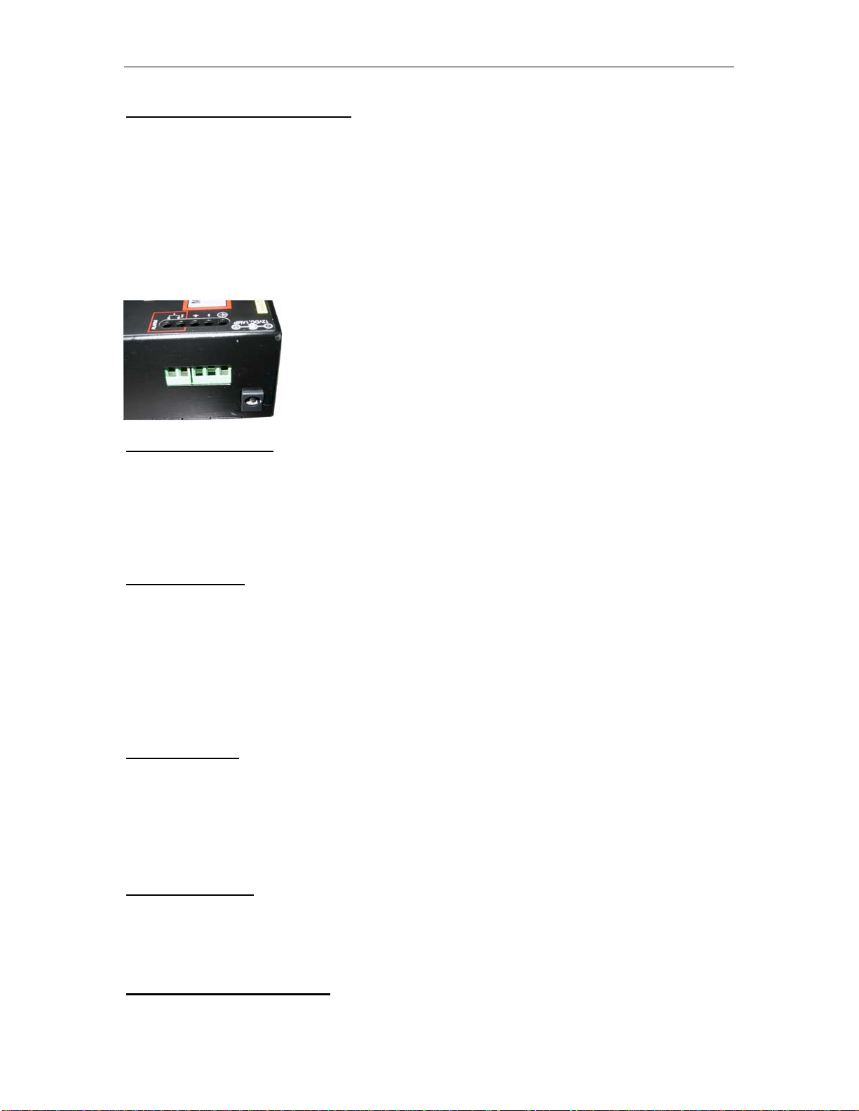
The external DC power plug connector and/or “jack” and the internal DC input
terminal is provided on the rear of the unit.
6

RFL 3000 –ES42H Ethernet Edge Switch Installation & User Guide (5/06)
2.3 Frame Buffering and Latency
The RFL 3000 ES42 Series Edge Switches are store-and-forward switches. Each
frame (or packet) is loaded into the Switch’s memory and inspected before forwarding
can occur. This technique ensures that all forwarded frames are of a valid length and
have the correct CRC, i.e. they are good packets. This eliminates propagation of bad
packets, enabling all of the available bandwidth to be used for valid information.
While other switching technologies such as "cut-through" or "express" impose
minimal frame latency, they will also permit bad frames to propagate to the Ethernet
network. The "cut-through" technique permits collision fragment frames, which are a
result of late collisions, to be forwarded--which add to the network traffic. There is no
way to filter frames with a bad CRC (the entire frame must be present in order for CRC
to be calculated). Since collisions and bad packets are more likely when traffic is heavy,
store-and-forward switch technology enables more bandwidth to be available for good
packets when the traffic load is greatest.
To minimize the possibility of dropping frames on congested ports, each RFL
3000 ES42 Series Edge Switch dynamically allocates buffer space from 128KB memory
pool, ensuring that heavily used ports receive very large buffer space for packet storage.
(Many other switches have their packet buffer storage space divided evenly across all
ports, resulting in a small, fixed number of packets to be stored per port. When the port
buffer fills up, dropped packets result.) This dynamic buffer allocation provides the
capability for the maximum resources of the RFL 3000 ES42 Series unit to be applied to
all traffic loads, even when the traffic activity is unbalanced across the ports. Since the
traffic on an operating network is constantly varying in packet density per port and in
aggregate density, the RFL 3000 ES42 Series Edge Switches are constantly adapting
internally to provide maximum network performance with the least dropped packets.
When the Switch detects that its free buffer queue space is low, the Switch sends
industry standard (full-duplex only) PAUSE packets out to the devices sending packets to
cause “flow control”. This tells the sending devices to temporarily stop sending traffic,
which allows a traffic catch-up to occur without dropping packets. Then, normal packet
buffering and processing resumes. This flow-control sequence occurs in a small fraction
of a second and is transparent to an observer.
Another feature implemented in RFL 3000 ES42 Series Edge Switches is a collision-
based flow-control mechanism (when operating at half-duplex only). When the Switch
detects that its free buffer queue space is low, the Switch prevents more frames from
entering by forcing a collision signal on all receiving half-duplex ports in order to stop
incoming traffic.
The latency (the time the frame spends in the Switch before it is sent along or
forwarded to its destination) of the RFL 3000 ES42 Series Edge Switches varies with the
port-speed types. The length of the frame is a variable as it is with all store-and-forward
switches. For 10 Mb-to-10 Mb, 10 Mb-to-100Mb or 100Mb-to-10 Mb forwarding, the
latency is 15 microseconds plus the packet time of 10 Mb. For 100Mb-to-100Mb
forwarding, the latency is 5 microseconds plus the packet time of 100Mb.
7

RFL 3000 –ES42H Ethernet Edge Switch Installation & User Guide (5/06)
2.4 Features and Benefits
Full 100Mb or 10 Mb switching services for high performance Ethernet
RFL 3000 ES42 Series Switches provide Fast Ethernet switching on all ports.
They perform high speed filter/forward operations on the traffic, giving each
port’s segment a full 100Mb (or 10 Mb) of bandwidth.
Reduces Network Costs and provide economical solution
RFL 3000 ES42 Series Switches offer the ideal solution to efficiently and
inexpensively connect a Twisted Pair and fiber network with 10Mb or 100Mb
and help to expand the Ethernet network in a very convenient and economical
way.
Choice of one or two100Mb Fiber option, more efficient Designed as a
multi-purpose media Edge Switch, the 100Mb fiber port allows the user to
convert the media from copper to fiber and the other RJ-45 port can be used as
diagnostic port or for more connectivity.
Installation is “Plug and Play”, operation is transparent to software
The RFL 3000 ES42 Series Switches operate as hardware switches, only
forwarding those packets from each domain that are needed on the other
domains. Internal address tables are self-learning, enabling users to change
port connections or 10/100 domains without affecting operations.
Two sets of LEDs for viewing status from any angle.
Each RFL 3000 ES42H Series Edge Switch is equipped with two sets (front
and side) of LEDs to provide status information when viewed at almost any
angle or mounting arrangement whether rack (MC14- Tray) or Din-Rail
mounted.
Rugged metal case, Industrial grade RFL 3000 ES42H Series have a robust design and
are packaged in a rugged sheet metal enclosure to ensure high reliability and durability
even when placed in industrial or outdoor applications.
Efficient Compact design, for all purpose convenient mounting
Featuring a compact steel case with an external AC and internal DC power
supply, RFL 3000 ES42 Series of Edge Switches can be installed in small
spaces in cabinets, on table tops, in racks, walls or DIN-Rail mounted and in
trays such as the RFL 3000 MC14-TRAY.
MDIX ports to eliminate cross-over cable while cascading All the RFL
3000 ES42 Series Switches are featured with MDIX (auto-cross), which easily
allow cascading with other Switch, Hubs or media Edges without using the
cross-over cable.
Hardware operated Alarm terminal block for RFL 3000 ES42H
The Alarm contact option on the RFL 3000 ES42H enables monitoring for
internal power failure, and provides extra reliability to the hardened Switch.
8

RFL 3000 –ES42H Ethernet Edge Switch Installation & User Guide (5/06)
9
2.5 Applications for RFL 3000 ES42H Series Edge Switches
Available in three “hardiness” models (Yellow - “office/wiring closet”, Orange –
“Hardened”, Red- “Premium rated (outdoor)”), and hundreds of port-type combinations,
RFL 3000 ES42 Series Edge Switches fit very well in almost any environment to enable
users to scale their networks quickly and cost effectively. The edge-of-the-network
connectivity solutions offered by RFL 3000 Edge Switches provide convenient,
economical, and reliable solutions as well as an active role on the managed redundant
network setup for faster recovery. The compact RFL 3000 ES42 Series assists fast
expanding network requirements via providing edge support and reliability to the
managed redundant network. The Dual-Speed and Dual-media functions support a mixed
environment of 10 Mbps and 100Mbps users with copper and fiber media. The switched
full duplex fiber port also provides high bandwidth and longer distance support. The up-
link feature of 100Mb fiber on Ports 1 and 2 enable easy expansion for the on-going
demand of Ethernet networks. The 10/100Mbps auto-negotiating MDIX copper ports and
the breadth of 100Mbps fiber ports enable easy interfacing with existing cable plant and
equipment. Models of RFL 3000 ES42H Edge Switches are available for even the most
extreme temperatures. The RFL 3000 ES42H’s rugged case provides extra support in the
harshest industrial environments. Link-Loss-Learn is an additional feature to provide the
extra reliability to the redundant network and an economical solution for faster recovery,
during the ring break.
Example1. Data Mining application for RFL 3000 ES42H
2 4 6 8
1 3 5 7
PWR
A
LARM
ONSOLE PORT
TX
TX
TX
TX
RX
RX
RX
RX
LK
LK
LK
LK
LK LK
LK
LK
LK
1
2
5
6
10/
100
1
C
A
CT
F/H
A
CT
F/H
A
CT
F/H
A
CT
F/H
A
CT
F/H
A
CT
F/H
A
CT
F/H
A
CT
F/H
7
GarrettCom Magnum 6K16
Managed Switch
10/
100
1
2
V
DC
1
AM
P
10F
OR
100A
OR
LK/
ACT
LK/
ACT
PWR
1
2
3
4
5
6
PORTPO
RT
1
2
3
4
5
6
ALARM
10/100
TX
RX
FH2
Premium
MagnumE42
S
EdgeSwitch
10/100
RX
TX
FH2
Magnum ES42 Premium
Edge Switch ver 2
10/
100
12
V
D
C
1
A
MP
10F
OR
100A
OR
LK/
ACT
LK/
ACT
PWR
1
2
3
4
5
6
PORT
POR
T
1
2
3
4
5
6
ALARM
10/100
TX RX
FH2
Premium
MagnumE42
S
EdgeSwitch
1
0
/1
0
0
RX
TX
FH2
Magnum ES42 Premium
Edge Switch ver 2
10/
100
1
2V
D
C1
A
M
P
10F
OR
100A
OR
LK/
ACT
LK/
ACT
PWR
1
2
3
4
5
6
PORT
PORT
1
2
3
4
5
6
ALARM
10/100
TX RX
FH2
Premium
MagnumE42
S
EdgeSwitch
10/100
RX
TX
FH2
Magnum ES42 Premium
Edge Switch ver 2
10/
100
12
V
DC
1
AM
P
10F
OR
100A
OR
LK/
ACT
LK/
ACT
PWR
1
2
3
4
5
6
PORTPO
R
T
1
2
3
4
5
6
ALARM
10/100
TX RX
FH2
Premium
MagnumE42
S
EdgeSwitch
10/100
RX
TX
FH2
Magnum ES42 Premium
Edge Switch ver 2
10/
100
1
2
V
D
C
1
AM
P
10F
OR
100A
OR
LK/
ACT
LK/
ACT
PWR
1
2
3
4
5
6
PORT
PO
R
T
1
2
3
4
5
6
ALARM
10/100
TX RX
FH2
Premium
MagnumE42
S
EdgeSwitch
1
0
/1
0
0
RX
TX
FH2
Magnum ES42 Premium
Edge Switch ver 2
10/
100
12
V
DC
1
A
M
P
10F
OR
100A
OR
LK/
ACT
LK/
ACT
PWR
1
2
3
4
5
6
POR
T
PO
R
T
1
3
5
ALARM
10/100
TX RX
FH2
Premium
MagnumE42
S
EdgeSwitch
10/100
RX
TX
FH2
Magnum ES42 Premium
Edge Switch ver 2
10/
100
12
V
D
C
1
A
MP
10F
OR
100A
OR
LK/
ACT
LK/
ACT
PWR
1
2
3
4
5
6
PORT
PO
R
T
1
2
3
4
5
6
ALARM
10/100
TX RX
FH2
Premium
MagnumE42
S
EdgeSwitch
10/100
RX
TX
FH2
Magnum ES42 Premium
Edge Switch ver 2

RFL 3000 –ES42H Ethernet Edge Switch Installation & User Guide (5/06)
In this example, the utility required a Data Mining function to store all the transaction
with an ongoing demand to expand the network. This need can be easily met using the
economical RFL 3000 ES42H Edge Switch. Additional functionality includes the ability
to transfer data across large distances with multi- or single–mode fiber while securing the
LAN from EMI and wire tapping.
The The RFL 3000 ES42’s six ports in a small, reliable enclosure provide an effective
solution to for transferring real-time transactions from the store to the storage device in
the control room. The easily deployable through Din-rail option and the dual power
source of flexibility along with flavor of fiber option for distance, the RFL 3000 ES42H
easily meets all the requirements of supermarket. The plug-n-play RFL 3000 ES42 not
only provides a reliable solution but also reduces operational costs significantly.
Example 2: RFL 3000 ES42H and CSN14H
In this industrial networking application, the new PLC units are deployed on a network
expansion, and each PLC required one (or two for redundancy) Ethernet ports to carry
status and control data to the control center. The RFL 3000 ES42H and CS14H provide a
good solution with their multiple options and hardened features. The two Fiber ports on
the Edge switches are ideal for secure data communications over long distances. Built
with high-grade components, efficient cooling techniques and having no openings for dirt
to enter, the RFL 3000 ES42 Series Edge Switches provide the very effective solution for
this need. The CS14H offers additional and affordable fiber connectivity to the RFL 3000
ES42H where needed.
1 3 5 7
9 11 13 15
17 19 21 23
2 4 6 8
10 12 14 16
18 20 22 2 4
A
CT
F/H
A
CT
F/H
A
CT
F/H
A
CT
F/H
A
CT
F/H
A
CT
F/H
A
CT
F/H
A
CT
F/H
2 4 6 8
1 3 5 7
GarrettCom
Magnum6K16V
PWR
CONSOLEPORT
GarrettCom
Magnum6K16V
PWR
CONSOLEPORT
GarrettCom
Magnum6K16V
PWR
CONSOLEPORT
GarrettCom
Magnum6K16V
PWR
CONSOLEPORT
10/
100
12VDC1AMP
10F
OR
100A
OR
LK/
ACT
LK/
ACT
PWR
1
2
3
4
5
6
PORT
PORT
1
2
3
4
5
6
ALARM
10/100
TX RX
FH2
Premium
MagnumE42
S
EdgeSwitch
1
0
/1
0
0
RX
T
X
FH2
10/
100
12VDC1AM
P
10F
OR
100A
OR
LK/
ACT
LK/
ACT
PWR
1
2
3
4
5
6
PORT
PORT
1
2
3
4
5
6
ALARM
10/100
TX RX
FH2
Premium
MagnumE42
S
EdgeSwitch
10/100
RX
TX
FH2
10/
100
12VDC1AMP
10F
OR
100A
OR
LK/
ACT
LK/
ACT
PWR
1
2
3
4
5
6
PORT
PORT
1
2
3
4
5
6
ALARM
10/100
TX RX
FH2
Premium
MagnumE42
S
EdgeSwitch
1
0
/1
0
0
RX
TX
FH2
10/
100
12VDC1AM
P
10F
OR
100A
OR
LK/
ACT
LK/
ACT
PWR
1
2
3
4
5
6
PORT
PORT
1
2
3
4
5
6
ALARM
10/100
TX RX
FH2
Premium
MagnumE42
S
EdgeSwitch
10/100
RX
TX
FH2
PLCPLC
PLCPLC PLCPLC
PLCPLC
iMac
iMaciMac
iMac
ES42H in a Industrial application
10

RFL 3000 –ES42H Ethernet Edge Switch Installation & User Guide (5/06)
Example 3: RFL 30000ES42H:
In this example, the RFL 3000 ES4H Edge Switches are deployed to serve as a secure
corporate or transportation surveillance system. CCTV cameras may be spread out over
many miles in temperature un-controlled locations and with pan, tilt and zoom (PTZ)
controlled through an Ethernet copper port .The Edge Switches provide two fiber
segments for secure long distance (2-40km) communication while being installed in
temperature un-controlled cabinets and allowing a full range of AC and DC power
options. The four copper ports at the remote location provides access for other Ethernet
equipment such as motion detectors or will act as a test port for maintenance personnel
with up-link for access to a central LAN and central file servers.
1 3 5 7
9 11 13 15
17 19 21 23
2 4 6 8
10 12 1 4 16
18 20 22 24
A
CT
F/H
A
CT
F/H
A
CT
F/H
A
CT
F/H
A
CT
F/H
A
CT
F/H
A
CT
F/H
A
CT
F/H
2 4 6 8
1 3 5 7
1
0/
100
12VDC1AM
P
1
0F
OR
1
00A
OR
LK/
ACT
LK/
ACT
PWR
1
2
3
4
5
6
PORT
PORT
1
2
3
4
5
6
ALARM
1
0
/
1
0
0
T
X
R
X
FH2
Premium
MagnumE42
S
EdgeSwitch
10/100
R
X
T
X
FH2
1
0
/
100
12VDC1AMP
1
0F
OR
1
00A
OR
LK/
ACT
LK/
ACT
PWR
12
3
4
5
6
P
ORT
PORT
1
2
3
4
5
6
ALARM
10/100
T
X
R
X
FH2
Premium
MagnumE42
S
EdgeSwitch
1
0
/
1
0
0
R
X
T
X
FH2
1
0/
100
12VDC1AMP
1
0F
OR
100A
OR
LK/
ACT
LK/
ACT
PWR
1
2
3
4
5
6
PORTPORT
1
2
3
4
5
6
ALARM
1
0
/
1
0
0
T
X
R
X
FH2
Premium
MagnumE42
S
EdgeSwitch
1
0
/
1
0
0
RX
T
X
FH2
iMac
iMac
iMac
ES42p in a Outdoor application
CCTV CameraCCTV Camera
CCTV CameraCCTV Camera CCTV CameraCCTV Camera
1
0
/
100
12VDC1AMP
1
0F
OR
1
00A
OR
LK/
ACT
LK/
ACT
PWR
12
3
4
5
6
PORT
PORT
1
2
3
4
5
6
ALARM
1
0
/
1
0
0
T
X
R
X
FH2
Premium
MagnumE42
S
EdgeSwitch
1
0
/
1
0
0
R
X
T
X
FH2
iMac
CCTV CameraCCTV Camera
1
0/
100
12VDC1AM
P
1
0F
OR
100A
OR
LK/
ACT
LK/
ACT
PWR
1
2
3
45
6
PORT
PORT
1
2
3
4
5
6
ALARM
1
0
/
1
0
0
T
X
R
X
FH2
Premium
MagnumE42
S
EdgeSwitch
1
0
/
1
0
0
R
X
T
X
FH2
iMac
CCTV CameraCCTV Camera
1
0/
100
12VDC1AM
P
1
0F
OR
100A
OR
LK/
ACT
LK/
ACT
PWR
1
2
3
4
5
6
PORT
PORT
1
2
3
4
5
6
ALARM
1
0
/
1
0
0
T
X
R
X
FH2
Premium
MagnumE42
S
EdgeSwitch
1
0
/
1
0
0
R
X
T
X
FH2
iMac
CCTV CameraCCTV Camera
11

RFL 3000 –ES42H Ethernet Edge Switch Installation & User Guide (5/06)
SECTION 3 INSTALLATION
This section describes the installation of the RFL 3000 ES42 Series Edge
Switches, including location, mountings, power supply options and media connection.
3.1 Locating the Edge Switch Unit
All the RFL 3000 ES42H Series Switches operate in transparent half-and full-
duplex mode. The store and forward switch easily takes care of network traffic and can
be used as a useful, economical tool to expand an existing network.
Secure attachment of mounting clips for panel - mounting
The compact and lightweight design of the RFL 3000 ES42 Series allows it to be
easily installed in almost any location. A Velcro strip may be used for mounting the unit
on a vertical surface such as a wall or cabinet, or for securing the unit on a table-top or
shelf. Alternatively, metal mounting clips and screws are included for a rugged and
secure mounting in any orientation.
Installation of the RFL 3000 ES42 Series Edge Switches is a simple procedure. The
installation location is dependent upon the physical layout of the Ethernet network and
associated cabling. Make sure the unit is installed in a location that is easily accessible to
an AC power outlet or the appropriate DC source and where cooling is not inhibited. The
green Power (PWR) LED must turn ON when power is applied.
3.2 MC14-TRAY for Rack Mounting of RFL 3000 ES42H Series Switches
For 19” rack-mounting of RFL 3000 ES42 series Edge Switches, a rack-mount
tray is available, the MC14-TRAY. The Edge Switches are mounted with the DC power
jack in the back, with the fiber and the RJ-45 connectors in the front. Any mix of the
Edge Switches and/or
12

RFL 3000 –ES42H Ethernet Edge Switch Installation & User Guide (5/06)
Media Edges may be placed on a tray, up to a maximum of 8 units. (The mounting spaces
of the MC14-TRAY are specific to the RFL 3000 products and will not permit other
models to be properly mounted).
In a typical installation, the MC14-TRAY, 19” rack-mount tray will hold a few (three to
eight) RFL 3000 ES42H Series Edge Switches, with their power supplies plugged into
power strips (not included) in the rear area of the tray. Metal mounting screws in the
bottom-front hold the Edge Switches firmly in place. The beveled-top edge of the units
permits the LEDs of each unit to be viewed for operational status, even when the units
are very close together.
3.3 MC14-TR+PS9 and MC14-TR+PS9X2 for Rack Mounting Media Edges
The MC14-TR+ PS9 and MC14-TR+PS9X2 are other options for rack mounting the mix
of RFL 3000 10Mbps and 100Mbps Edge Switches and Media Edges together in a 19”
rack-mount tray. These models come with built-in common universal AC power supply
rated at 55 watts at 50°C ambient,9VDC output, and supporting up to 2-3 Switches for
MC14-TR+PS9 and 5 units RFL 3000 ES42H Series for MC14-TR+PS9X2. The MC14-
TR+PS9X2 Model has two groups of eight units per power supply. The power supplies
have auto-ranging AC input for use worldwide.
The side-view < here is an example of an installation of the model MC14-TR+PS9, 19”
rack-mount tray, holding a few RFL 3000 ES42H, and 14E Media Edges, each with their
power input plugged into the built-in common AC power supply in the rear area of the
tray. (AC PS units that come with the office models of the Edge Switch’s are not used).
Because of the thicker size, only eight RFL 3000 ES42H units can fit in one MC14-
TRAY.
Metal mounting screws in the bottom-front hold each of the Edge Switches,
securing them in the tray and enabling separate removal for service. The dual LEDs
permit viewing of Edge Switch status from any angle.
13

RFL 3000 –ES42H Ethernet Edge Switch Installation & User Guide (5/06)
3.4 DIN-Rail mounting option
The RFL 3000 ES42H Edge Switches, designed for use in Industrial Ethernet
environments, are available for DIN-Rail mounting in an enclosure having DIN Rails
The metal DIN-Rail mounting hardware is optional and needs to be ordered as a
separate item, e.g. Model #DIN-RAIL-MC2. It comes with four screws to attach the
bracket to the MC unit. The rail clip is spring-loaded with a pull-up latch at the top for
easy “snap-on” attachment and removal.
The RFL 3000 ES42 models with “HR” have 24VDC power, and have the DIN-
Rail-MC2 bracket included and assembled with the MC unit at the factory.
3.5 Power Requirements, Power Supply Types for RFL 3000 ES42H Series
Switches
RFL 3000 ES42 Series Switches are power-efficient and can work with an
external AC power supply. RFL 3000 ES42 Series require a nominal 12VDC input
version.
The 12V DC power input jack has a plug of 2.5mm, center +ve , with 6 ft. cord. All the
AC power supply info detail is provided in Technical Specs Section 1.1.
The RFL 3000 ES42 Series is designed to be used with UL listed Class II power supplies.
RFL 3000 ES42H 12VDC/ 24VDC/ -48VDC
The RFL 3000 ES42 Edge Switches provide reliable operation, withstand higher
temperature environments, and provide the DC power choices to the user to deploy in
uncontrolled temperature environments.
The Direct DC (Internal) 12V DC (8 – 15V DC) has a built-in terminal block for +, -,
ground. The 9V DC jack is also present. Detail information about the 12 VDC, the 24V
DC and the –48V DC is provided in the Technical Specifications Section 1.1.
The various models of DC power type and extended ambient temperature power supplies
are numerous and your choice needs to be called out on your order.
14

RFL 3000 –ES42H Ethernet Edge Switch Installation & User Guide (5/06)
Note: When connected to a -48 V centralized dc source these products are to be installed
only in Restricted Access Areas (dedicated equipment rooms, electrical closets or the
like).
3.6 Powering the RFL 3000 ES42H (DC internal) with 12V, 24V or –48VDC power
input
Each RFL 3000 ES42H is equipped with an internal DC power supply, and has
built-in screw terminals for secure attachment of the power input leads. Three DC power
models support a range of power input types. The three DC power input terminal block
choices are for use with 12VDC, 24VDC or -48VDC power. Where an AC power
adaptor is used, DC is supplied via the jack. Power input from the DC terminal block and
the jack and both may be connected simultaneously for power input redundancy.
Note: TheRFL 3000 ES42H 24VDC support the Dual Source 24V input option. An
external Dual-SRC-24KIT (SHOWN AT RIGHT…and sold separately, or a customer-
supplied equivalent) can be used to input 24VDC power to the ES4H or P unit via the
jack. This is for 24VDC models only.
15

RFL 3000 –ES42H Ethernet Edge Switch Installation & User Guide (5/06)
3.6 continued, DC Power Terminals: “+”, “-”, gnd
GND: Terminal for “earth” or ground wire connection to the RFL 3000 ES42HH chassis
Input Voltage: 12VDC 24VDC -48VDC
Input current:
(12V or 24V)
(10-30VDC)
24VDC
(10-36VDC)
(12V)
(8-15VDC)
(12V)
(8-15VDC)
-48VDC
(30-60VDC)
12VDC
(8-15VDC)
Alarm
C
ontact
Terminal
0.8 amp.(12V DC)
0.4 amp max.(24V DC)
0.2 amp max.(-48V DC)
Power Consumption: 7 watts typical, 9 watts max.
3.7 RFL 3000 ES42H DC-powered, 12VDC, 24VDC and -48VDC Installation
This section describes the proper connection of the -48VDC leads (or 24VDC,
12VDC leads) to the DC power terminal block on the RFL 3000 ES42H Edge Switch (as
shown in the Figure). The DC terminal block on the RFL 3000 ES42H is located on the
left side of the unit and is equipped with three (3) screw-down lead posts. The power
terminals are identified as positive (+) and negative (-), and they are floating inside the
unit so that either of the terminals may be grounded by the user if desired. The chassis is
“earth” or ground (GND). The connection procedure is straightforward. Simply insert the
DC leads to the RFL 3000 ES42HH’s power terminals, positive (+) and negative (-)
screws. The use of Ground (GND) optional; it connects to the RFL 3000 ES42HH
chassis. Ensure that each lead is securely tightened from the top, as shown on above
picture with arrow.
NOTE:
Always use a voltmeter to measure the voltage of the incoming power supply and figure
out the +ve potential lead or -ve potential lead. The more +ve potential lead will
connect to the post labeled “+ve” and the rest to the “-ve”.
The GND can be hooked up at the last.
When power is applied, the green PWR LED will illuminate.
16
Table of contents
Popular Switch manuals by other brands

Sunbox
Sunbox VHW201KS user manual

Mid-West Instrument
Mid-West Instrument 130 Series Installation and operating instructions

Siemens
Siemens SIMATIC NET SCALANCE X-200 operating instructions

Wise
Wise P535 instruction manual

sauter
sauter EGH102F901 Operating Instructions, Mounting & Installation

D-Link
D-Link DXS-3400 SERIES quick start guide