RFM DR-TRC103-EV Series User manual

www.RFM.com Technical support +1.800.704.6079 Page 2 of 11
©2009-2010 by RF Monolithics, Inc. E-mail: info@rfm.com DR-TRC103-EV 04/05/10
Introduction
The DR-TRC103 series evaluation kits include the radio boards, antennas and battery
packs used in the DR-TRC103 series development kits. The evaluation kits can be used
for initial evaluation of TRC103 radio technology and to prototype applications that will
use the TRC103 RFIC. This user guide covers the following evaluation kits:
Evaluation Kit Part Number Operating Frequency Range
DR-TRC103-868-EV 863 - 870 MHz
DR-TRC103-915-EV 902 - 928 MHz
DR-TRC103-950-EV 950 - 960 MHz
Table 1 - Evaluation Kit Part Numbers
Each DR-TRC103 evaluation kit contains the following items:
•2 DR-TRC103 Evaluation Boards
•2 Dipole Antennas
•2 AA Battery Packs
•4 AA Batteries
The DR-TRC103 radio board connectors and user controls are shown in Figure 1.
Figure 1 - DR-TRC103 Radio Board Connectors and Controls

www.RFM.com Technical support +1.800.704.6079 Page 3 of 11
©2009-2010 by RF Monolithics, Inc. E-mail: info@rfm.com DR-TRC103-EV 04/05/10
The DR-TRC103 radio board LED indicator names and locations are shown in Figure 2.
Figure 2 - DR-TRC103 Radio Board LED Indicators
Table 2 summarizes the functions of the DR-TRC103 connectors, user controls
and LED indicators.
Control/Indicator Designator Function
I/O Connector J2 20-pin connector for power and logic signal I/O
Battery Connector J3 Radio board “battery” power connector, 2.7 to 3.6 V
Battery Power Switch SW1 On/off switch, in line with the battery connector
Mode Switch SW2 Used to set the radio mode
Range Switch SW3 Used to set up range testing and data terminal functions
TX Power Adj Pot R7 Transmitter power adjustment potentiometer
Antenna Connector RF-IO 50 ohm antenna connector, standard SMA
Current Monitor Pins J1 Remove jumper from these pins to measure TRC103 current
Serial/PLL LED D1 Yellow LED blinks to indicate serial activity and PLL locking
TRC103 SPI LED D2 Yellow LED blinks to indicate SPI activity to/from the TRC103
Packet Error LED D3 Red LED blinks to indicate received packet failed CRC check
Good Packet LED D4 Green LED blinks to indicate received packet passed CRC check
MODE LED D5 Green/yellow LED color indicates mode of operation
RANGE LED D6 Yellow LED blinks to indicate range test or data terminal operation
Low Battery LED D7 Red LED illuminates to indicate low battery (must be configured)
Table 2 - DR-TRC103 Connector, Control and Indicator Functions
Powering the Radio Boards
Two AA battery packs are supplied in the evaluation kit to power the radio boards, as
shown in Figure 3. Alternately, a regulated power supply in the range of 2.7 to 3.6 volts

www.RFM.com Technical support +1.800.704.6079 Page 4 of 11
©2009-2010 by RF Monolithics, Inc. E-mail: info@rfm.com DR-TRC103-EV 04/05/10
can be used to power the radio boards. Note - there are no voltage regulators on the
radio boards. Applying a voltage outside the specified power supply range can damage
the boards. Do not attempt to power a radio board directly through its battery connector
using one of the 4.5 volt wall-plug power supplies provided in a DR-TRC103-DK series
development kit. The 4.5 volt power supplies are used to power the development kit
interface boards, which in turn provide regulated 3 volts to the radio boards. See the
DR-TRC103-DK User’s Guide for additional details.
Figure 3 - Powering the Radio Board from a Battery Pack
Initial Testing Using the Range Test Function
1. Install batteries in both battery cases and plug the cases into the radio boards.
2. Turn on the boards by sliding the switch as indicated in Figure 1. All LED’s will flash
and the MODE LED will be green.
3. On one board, briefly press and release the RANGE button. The RANGE LED will
illuminate continuously. This is the “receiving”board.
4. On the other board, press and hold the RANGE button until the LED’s begin
flashing. This board is the “transmitting”board.
5. If the radio boards are receiving good packets then the green Good Packet LEDs will
be flashing alternately on each board (plus various yellow LEDs).
6. To verify that the radio boards are operating properly, disable the “receiving”board
by pressing and releasing the RANGE button twice. The RANGE LED will turn off.
On the transmitting board, you should observe the red Packet Error LED flashing.
This indicates that the transmitter sent a packet but did not receive an acknowl-
edgment back from the “receiving”radio board.

www.RFM.com Technical support +1.800.704.6079 Page 5 of 11
©2009-2010 by RF Monolithics, Inc. E-mail: info@rfm.com DR-TRC103-EV 04/05/10
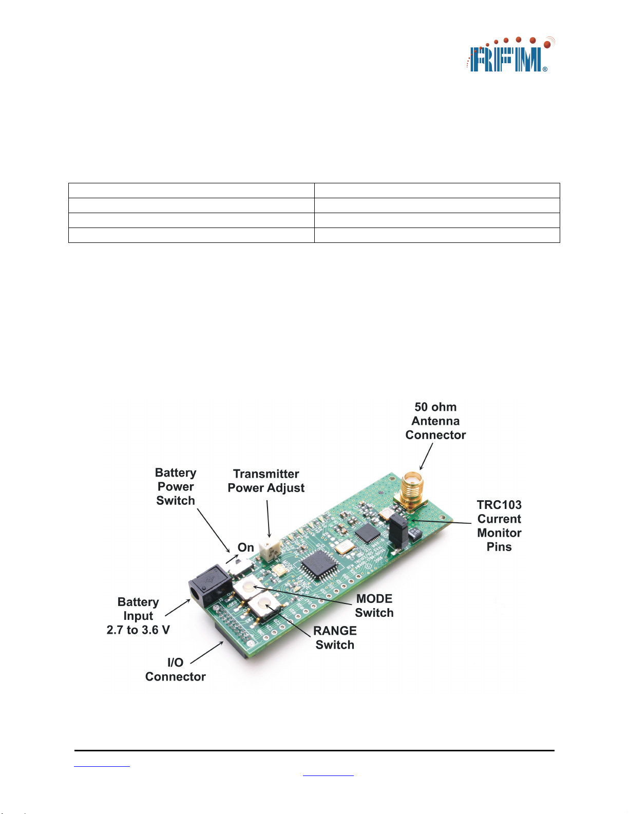
Radio Board Configuration
When a DR-TRC103 radio board is initially power on, it is configured as follows:
Operating Frequency:
DR-TRC103-868-EV 868.35 MHz
DR-TRC103-915-EV 916.50 MHz
DR-TRC103-950-EV 950.00 MHz
Power: +10 dBm
Frequency Deviation: ±50 kHz
Data Rate: 25 kb/s
Receiver Baseband Bandwidth: 100 kHz
The radio board is also initially configured in Receive Continuous Mode (see the
TRC103 datasheet for an explanation of continuous data mode, buffered data mode,
packet data mode, etc.). In receive continuous mode, the MODE LED will be green.
Receive continuous mode allows the user to connect a modulated signal from an RF
signal generator onto the board through a short coaxial cable and verify the demod-
ulated signal with an oscilloscope at the DAT pin.
Briefly pressing the MODE button once configures the board into Transmit Continuous
Mode. The Mode LED will change color from green to yellow. This mode turns on the
transmitter. The frequency and output power may be verified with a spectrum analyzer.
A square-wave modulating signal may be applied to the DAT pin and the spectrum
observed on a spectrum analyzer.
Briefly pressing the MODE button again configures the board into Sleep Mode. The
Mode LED will turn off. By connecting an ammeter across the terminals of J1, with the
jumper removed, the user can verify the very low sleep current of the TRC103 device.
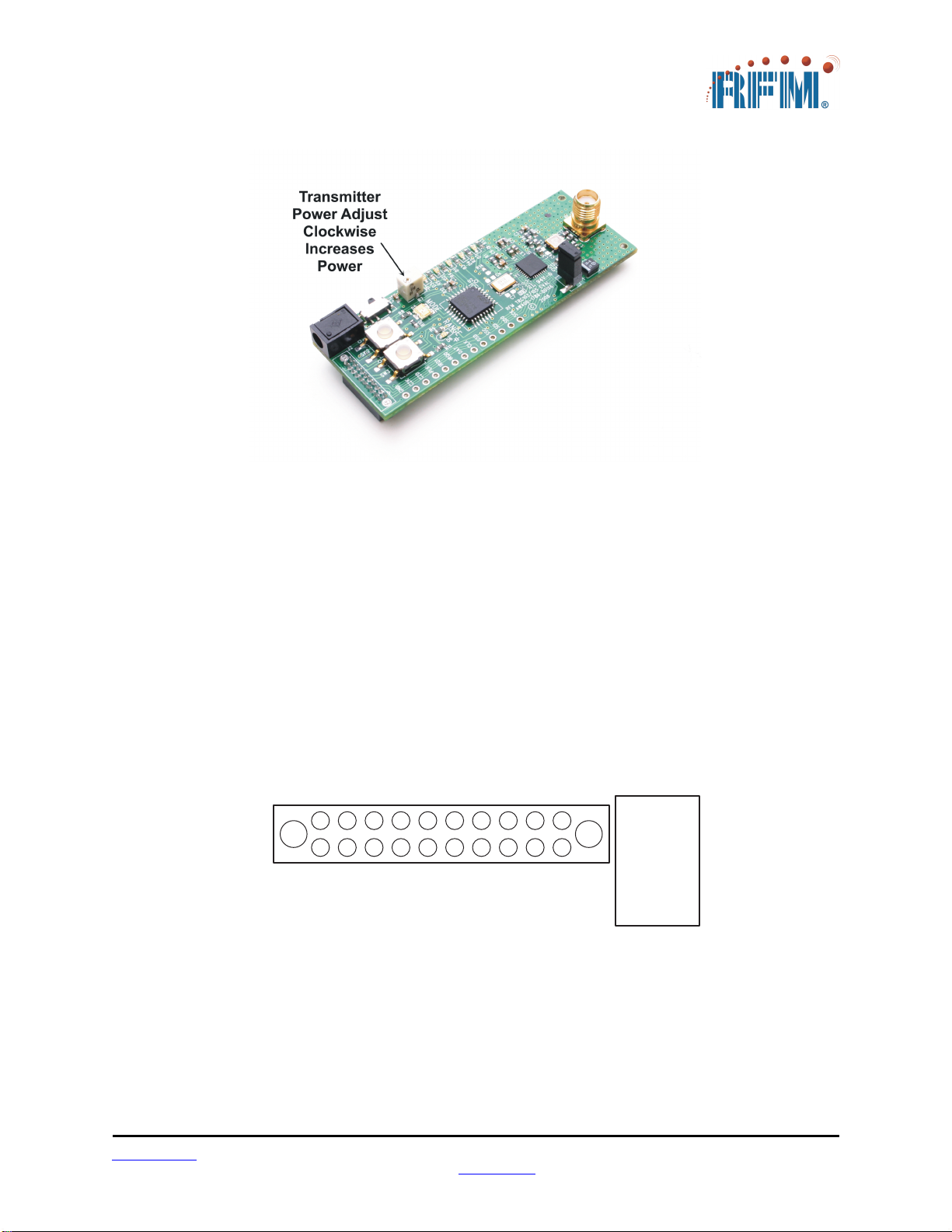
As shown in Figure 4, potentiometer R7 can be used to adjust the transmit power level.
To increase the output power, rotate the potentiometer screw clockwise. To decrease
the power, rotate the potentiometer screw counterclockwise. The transmit power is
divided into 8 levels. Adjusting R7 adjusts the voltage level to the A-to-D converter
(ADC) in the host microcontroller. The microcontroller periodically samples R7 for a
change, and updates the transmit power register when it detects a change in voltage
level. Each time the microprocessor updates the transmit power register the SPI LED
will flash indicating an SPI write.

www.RFM.com Technical support +1.800.704.6079 Page 6 of 11
©2009-2010 by RF Monolithics, Inc. E-mail: info@rfm.com DR-TRC103-EV 04/05/10
Figure 4 - Radio Board Transmit Power Adjustment
Radio Board Interface Connector
Figure 5 shows the pin numbering detail of connector J2 on the edge of the DR-TRC103
radio boards. Figure 5 can be used with the schematics in the last section of this
manual to design an application interface for the radio boards. Note that all signal levels
into and out of this connector are nominally 3 V logic level. Attempting to use RS232
signal levels to directly interface the radio board can damage it.
1
2
1 9
2 0
35791 1 1 3 1 5 1 7
1 81 6
1 4
1 2
1 0
8
46
J 2
J 3
J 2 p i n n u m b e r i n g a s v i e w e d f r o m t h e t o p o f a
D - T C 1 0 3 r a d i o b o a r d ( c o n n e c t o r p o i n t s d o w n )
J 2 i s a S A M T E C S F M L - 1 1 0 - T 1 - S - D - L C
T h e m a t i n g c o n n e c t o r f o r J 2 i s a
S A M T E C T F M L - 1 1 0 - 0 1 - S - D - L C
Figure 5 - Radio Board J2 Pin Numbering Detail

www.RFM.com Technical support +1.800.704.6079 Page 7 of 11
©2009-2010 by RF Monolithics, Inc. E-mail: info@rfm.com DR-TRC103-EV 04/05/10
Radio Board Documentation
The schematics of each radio board and the top assembly view are provided on the
following pages. Also see the TRC103 Data Sheet, the DR-TRC103-DK Development
Kit User’s Guide and the RFIC Design Assistant utility software and related User’s
Guide. The latest versions of the Data Sheet, User’s Guides and the RFIC Design
Assistant utility software can be downloaded from RFM’s web site, www.rfm.com.
This manual suits for next models
3
Popular Motherboard manuals by other brands

ECS
ECS H67H2-1 manual

Texas Instruments
Texas Instruments LM5180-Q1 user guide

Phytec
Phytec phyBOARD-Wega AM335x quick start guide

Texas Instruments
Texas Instruments TMP468EVM user guide

Texas Instruments
Texas Instruments XTR300EVM user guide

Microchip Technology
Microchip Technology EVB-USB7056 user guide