INTRODUCTION
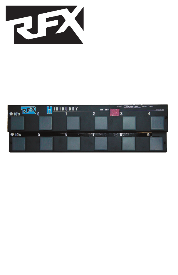
Thank you for purchasing the RFX MP128 MIDIBUDDY. The MP128 sends stan-
dard MIDI program changes to select patches on a MIDI keyboard, digital signal
processor, or other MIDI controllable device.
DESCRIPTION
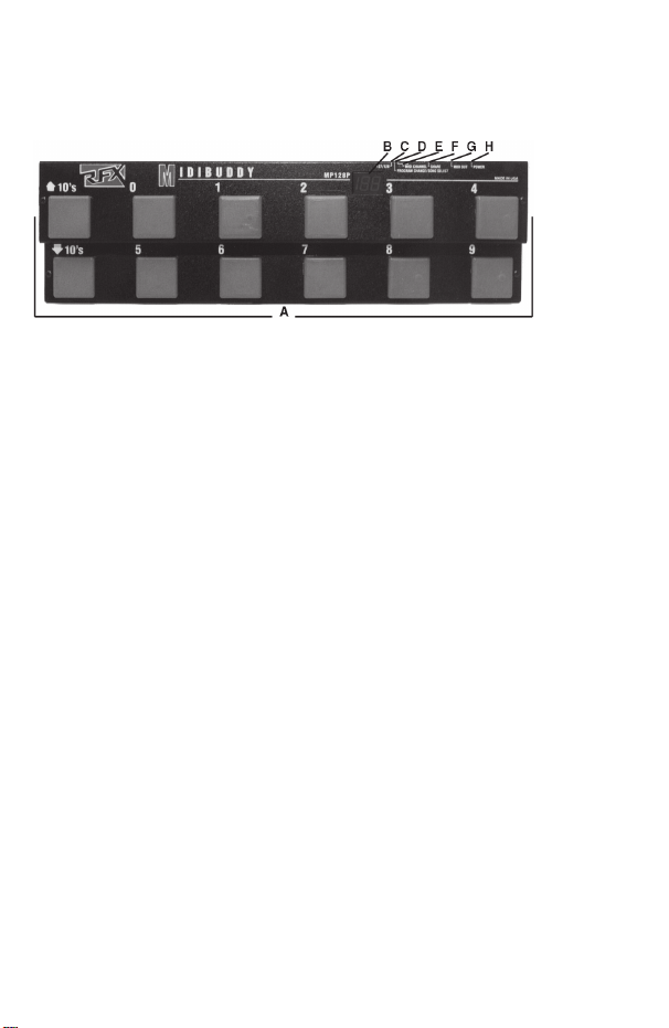
A. Program Select, Function buttons
B. Program/Function Display Window
C: 127/128 (Dip switch #6) Switch
D: PROGRAM CHANGE/SONG SELECT (DIP switch # 5) Switch
E: MIDI CHANNEL SELECT Switches (DIP switches 4,3,2, and 1)
F: SHARE output
G: MIDI output jack
H: POWER jack
INSTALLATION
• Apply power (Rolls Model PS27, 12VDC, 150mA) to the Power jack on the rear
of the MP128. The MP128 may also be "phantom-powered" which means power-
ing the unit via unused pins of the MIDI cable. See the back page of this manual
for more on MIDI phantom power.
• Connect the MIDI OUT of the MP128 using a standard MIDI cable, to the MIDI
IN on the device to be controlled. The MIDIBUDDY may be used on the floor and
foot switched or placed on top of a keyboard for easy hand access. The unit, with
slight modification, will fit in a standard 19 inch audio rack if necessary.
• The "SHARE" jack is in parallel with the OUT jack and operates as a MIDI
"Thru" for connecting several devices together. For example, two MP128s oper-
ating on different MIDI channels could use the same MIDI path.
OPERATION
The MP128 follows MIDI standard protocol, and will change programs on any
MIDI controllable device. The controlled device and the MP128 must be on the
same MIDI channel (see chart - next page), or the device should be on an "omni"
channel.
The unit sends up to ten different program changes, in twelves different banks.
Bank 0 sends program changes 1 - 9 (there is no program change 0), bank 1
sends program changes 10 - 19, bank 2 sends program changes 20 - 29, etc.
The LED display on the MIDIBUDDY shows the MIDI program number (0 - 127,
or 1 - 128 depending on the setting of DIP switch # 6).
As the 10s Up or Down are scrolled through, the unit increments or decrements
through banks 0 through 120. The ones digit is selected by switches 0 - 9. MIDI
data is sent only when a 1 - 9 button is selected except as described below.
The display will show a "-" in the right hand digit when no MIDI information is
sent,or when a 10's UP or DOWN button is pressed.
For example; to send program 47, press the 10s UP or 10s DOWN until the dis-
play reads "4-" then press the 7 button. When the 7 button is pressed, program
47 is sent out and the number is displayed by the LED readout.
MIDI Start and Stop Commands
When program "00" is selected, the MP128 display shows an "ST" (which looks
more like an Sr), and sends a MIDI start command. This may be used to start
a MIDI sequencer. When program "129" is selected, an "SP" is displayed and a
MIDI Stop command is sent.
Setting the DIP Switches
NOTE: DISCONNECT THE POWER CABLE TO MAKE DIP SWITCH CHANG-
ES. SETTINGS TAKE EFFECT UPON POWER-UP.
The MIDI Channel is set with DIP switches 1 - 4 on the rear of the MP128. If all
switches are in the off position, MIDI channel 1 is selected, if all are on, MIDI
channel 16 is selected. Use the following chart to select the MIDI Channel.
CH# ON OFF CH# ON OFF
1 1,2,3,4 9 4 1,2,3
2 1 2,3,4 10 1,4 2,3
3 2 1,3,4 11 2,4 1,3
4 1,2 3,4 12 1,2,4 3
5 3 1,2,4 13 3,4 1,2
6 1,3 2,4 14 1,3,4 2
7 2,3 1,4 15 2,3,4 1
8 1,2,3 4 16 1,2,3,4
• Switch #5 selects whether the MP128 transmits Program Change information
only, or transmits Program Change and Song Pointer.
• Since some MIDI devices display their programs as 0 - 127, and others display
1 - 128, the MIDIBUDDY's DIP switch #6 will select either of these two. If switch
#6 is in the off (up) position, the MP128 will display program numbers 0 - 127. If
switch #6 is on (down), the MP128 will display program numbers 1 - 128 (which
is the way the MP128 comes from the factory).