RGBlink RGB20X-NAI-GY User manual

Educational Tracking Camera
RGB20X-NAI-GY
User Manual

© Xiamen RGBlink Science & Technology Co., Ltd.
1
Content
Declarations.................................................................................................................................................................... 4
FCC/Warranty..............................................................................................................................................................4
Operators Safety Summary......................................................................................................................................... 5
Installation Safety Summary....................................................................................................................................... 5
Chapter 1 Your Product................................................................................................................................................ 6
1.1 In the Box.............................................................................................................................................................. 6
1.2Product Overview.................................................................................................................................................. 6
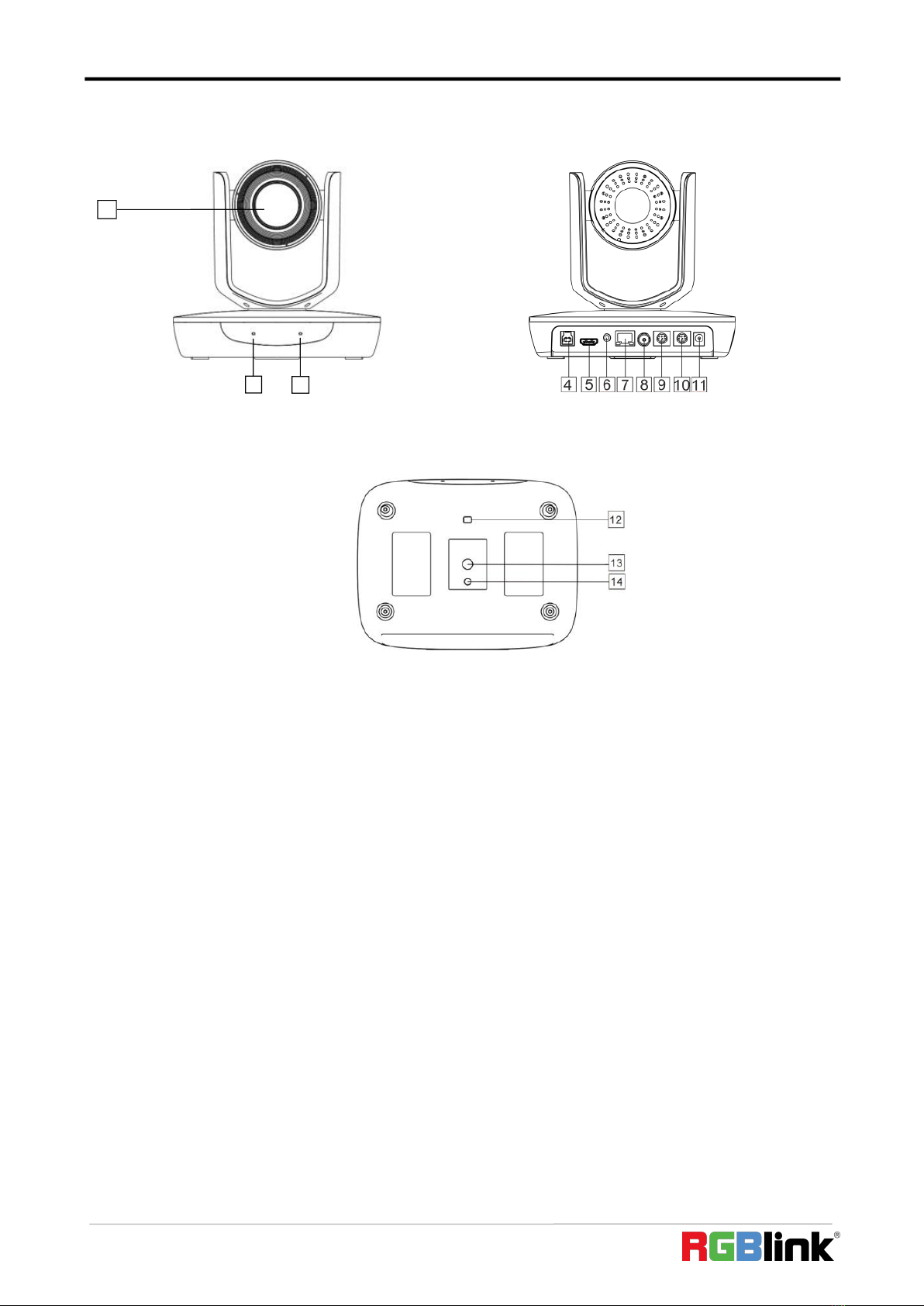
1.2.1 Interface......................................................................................................................................................... 7
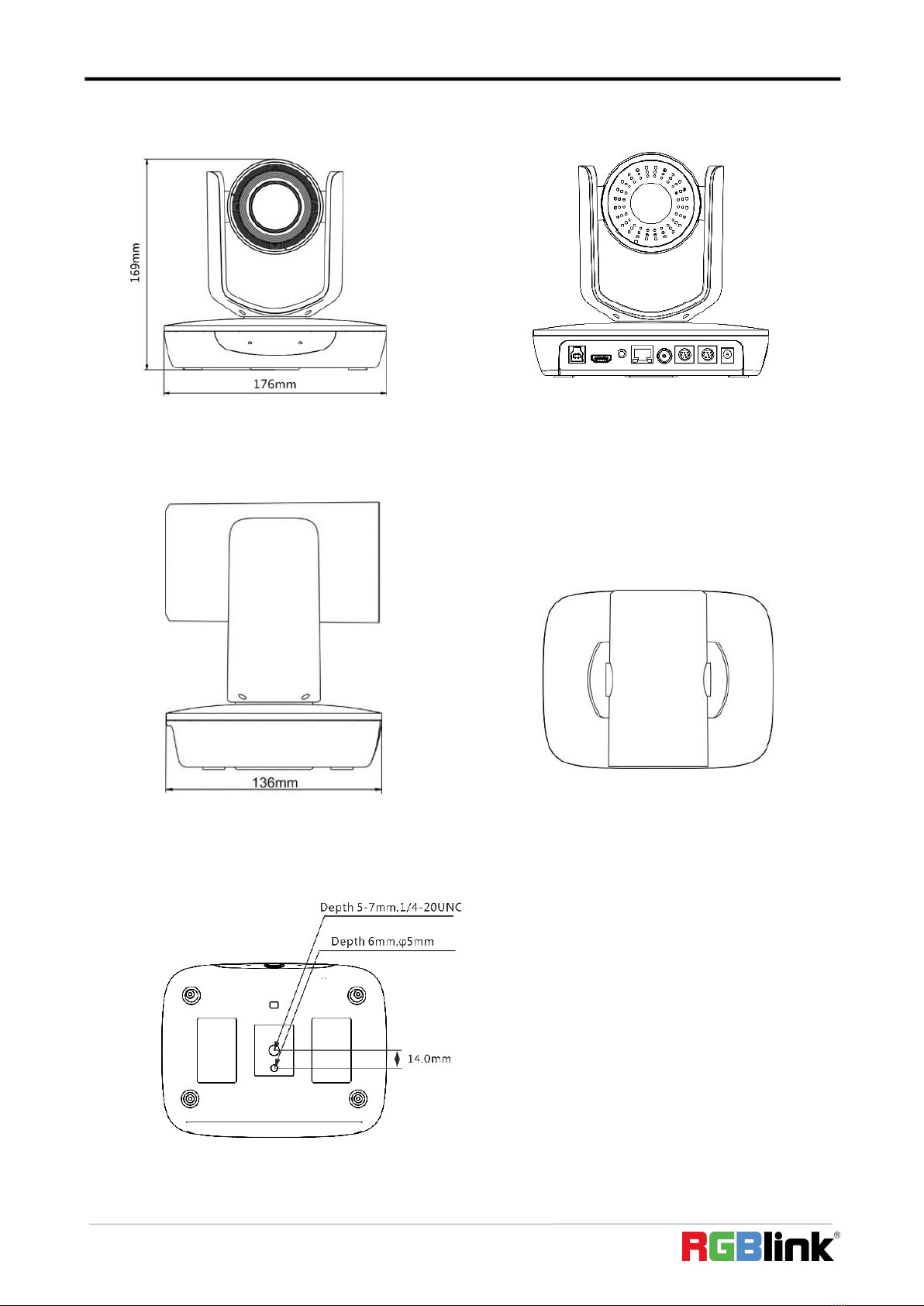
1.2.2 Dimension.................................................................................................................................................... 10
Chapter 2 Install Your Product..................................................................................................................................... 11
2.1 Installation...........................................................................................................................................................11
2.1.1 Desktop Mount Installation......................................................................................................................... 11
2.1.2 Wall Mount Installation(Optional)...............................................................................................................11
2.2 Connection.......................................................................................................................................................... 12
Chapter 3 Use Your Product.........................................................................................................................................13
3.1 Remote Controller...............................................................................................................................................13
3.2 Menu................................................................................................................................................................... 15
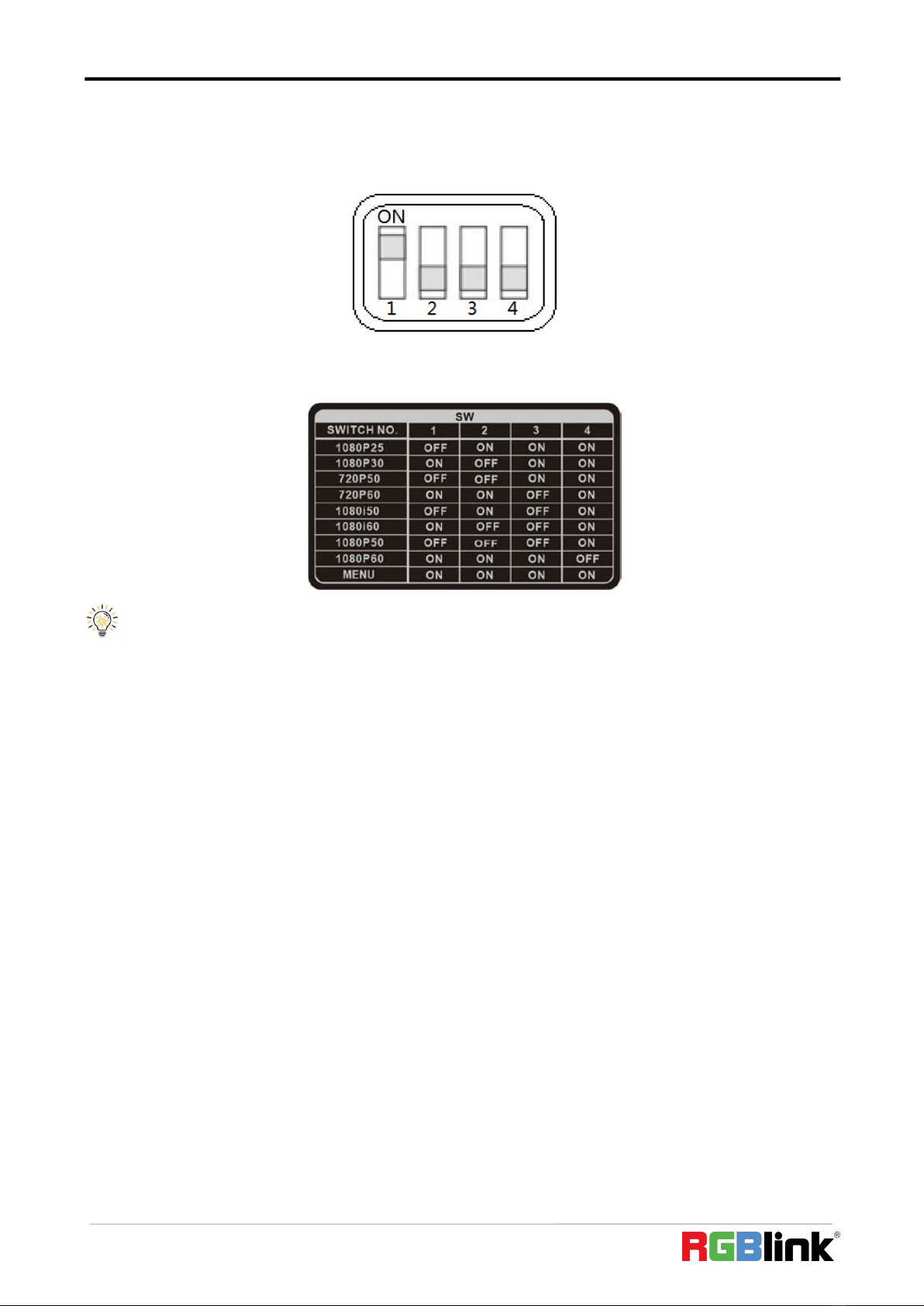
3.2.1 Menu Settings.............................................................................................................................................. 15
3.2.2 Menu Explanation........................................................................................................................................17
3.3 Network Connection...........................................................................................................................................21
3.3.1 LAN Connection........................................................................................................................................... 21
3.3.2 WAN Connection..........................................................................................................................................21
3.4 Client Software Instruction................................................................................................................................. 23
3.4.1 Search and List the Camera......................................................................................................................... 23
3.4.2 Preview.........................................................................................................................................................24
3.4.3 Settings.........................................................................................................................................................25
Chapter 4 Ordering Codes............................................................................................................................................28
4.1 Product................................................................................................................................................................28
Chapter 5 Support........................................................................................................................................................ 29
5.1 Contact us............................................................................................................................................................29
5.2 Trouble Shooting................................................................................................................................................. 30
Chapter 6 Appendix......................................................................................................................................................31
6.1 Specification........................................................................................................................................................31
6.2 VISCA Protocol List.............................................................................................................................................. 32
6.2.1 Camera Return Command........................................................................................................................... 32
6.2.2 Camera Control Command.......................................................................................................................... 33
6.2.3 Inquiry Command........................................................................................................................................ 36
6.3 Pelco-D Protocol Command List......................................................................................................................... 37

© Xiamen RGBlink Science & Technology Co., Ltd.
2
6.4 Pelco-P Protocol Command List..........................................................................................................................38
6.5 Terms & Definitions.............................................................................................................................................39
6.6 Revision History...................................................................................................................................................44

© Xiamen RGBlink Science & Technology Co., Ltd.
4
Thank you for choosing our product!
This User Manual is designed to show you how to use this video processor quickly and make use of all the
features. Please read all directions and instructions carefully before using this product.
Declarations
FCC/Warranty
Federal Communications Commission (FCC) Statement
This equipment has been tested and found to comply with the limits for a class A digital device, pursuant to Part 15
of the FCC rules. These limits are designed to provide reasonable protection against harmful interference when the
equipment is operated in a commercial environment. This equipment generates, uses, and can radiate radio
frequency energy and, if not installed and used in accordance with the instruction manual, may cause harmful
interference to radio communications. Operation of this equipment in a residential area may cause harmful
interference, in which case the user will be responsible for correcting any interference.
Guarantee and Compensation
RGBlink provides a guarantee relating to perfect manufacturing as part of the legally stipulated terms of
guarantee. On receipt, the purchaser must immediately inspect all delivered goods for damage incurred during
transport, as well as for material and manufacturing faults. RGBlink must be informed immediately in writing of
any complains.
The period of guarantee begins on the date of transfer of risks, in the case of special systems and software on the
date of commissioning, at latest 30 days after the transfer of risks. In the event of justified notice of compliant,
RGBlink can repair the fault or provide a replacement at its own discretion within an appropriate period. If this
measure proves to be impossible or unsuccessful, the purchaser can demand a reduction in the purchase price or
cancellation of the contract. All other claims, in particular those relating to compensation for direct or indirect
damage, and also damage attributed to the operation of software as well as to other service provided by RGBlink,
being a component of the system or independent service, will be deemed invalid provided the damage is not
proven to be attributed to the absence of properties guaranteed in writing or due to the intent or gross negligence
or part of RGBlink.
If the purchaser or a third party carries out modifications or repairs on goods delivered by RGBlink, or if the goods
are handled incorrectly, in particular if the systems are commissioned operated incorrectly or if, after the transfer of
risks, the goods are subject to influences not agreed upon in the contract, all guarantee claims of the purchaser will
be rendered invalid. Not included in the guarantee coverage are system failures which are attributed to programs or
special electronic circuitry provided by the purchaser, e.g. interfaces. Normal wear as well as normal maintenance
are not subject to the guarantee provided by RGBlink either.
The environmental conditions as well as the servicing and maintenance regulations specified in this manual must be
complied with by the customer.

© Xiamen RGBlink Science & Technology Co., Ltd.
5
Operators Safety Summary
The general safety information in this summary is for operating personnel.
Do Not Remove Covers or Panels
There are no user-serviceable parts within the unit. Removal of the top cover will expose dangerous voltages. To
avoid personal injury, do not remove the top cover. Do not operate the unit without the cover installed.
Power Source
This product is intended to operate from a power source that will not apply more than 230 volts rms between the
supply conductors or between both supply conductor and ground. A protective ground connection by way of
grounding conductor in the power cord is essential for safe operation.
Do Not Operate in Explosive Atmospheres
To avoid explosion, do not operate this product in an explosive atmosphere.
Installation Safety Summary
Safety Precautions
For all product installation procedures, please observe the following important safety and handling rules to avoid
damage to yourself and the equipment.
To protect users from electric shock, ensure that the chassis connects to earth via the ground wire provided in the
AC power Cord.
The AC Socket-outlet should be installed near the equipment and be easily accessible.
Unpacking and Inspection
Before opening product shipping box, inspect it for damage. If you find any damage, notify the shipping carrier
immediately for all claims adjustments. As you open the box, compare its contents against the packing slip. If you
find any shortages, contact your sales representative.
Once you have removed all the components from their packaging and checked that all the listed components are
present, visually inspect the system to ensure there was no damage during shipping. If there is damage, notify the
shipping carrier immediately for all claims adjustments.
Site Preparation
The environment in which you install your product should be clean, properly lit, free from static, and have adequate
power, ventilation, and space for all components.

© Xiamen RGBlink Science & Technology Co., Ltd.
6
Chapter 1 Your Product
1.1 In the Box
Power Adapter × 1
RS232 Serial Cable × 1
Remote Control × 1
1.2Product Overview
Key Features
Built-in industry-leading body detection and lock tracking image algorithm
1/2.8 inch CMOS sensor, 2.14 megapixel
20X optical zoom, Max FOV: 59.5°
Support HDMI, 3G-SDI, Network, USB, up to 1080P60 video output
1 channel audio LINE IN, AAC Compression
Support two modes of power supply, POE power supply or adapter power supply
Support VISCA interface and protocol, support flow control
Dual stream
Support NDI®|HX

© Xiamen RGBlink Science & Technology Co., Ltd.
7
1.2.1 Interface
Front View Rear View
Bottom View
1. Camera
2. Communication indicator
3. Power indicator
4. USB port
5. HDMI video output port
6. LINE IN port
7. Network port
8. SDI port
9. RS-232IN/IR port
10. RS-232OUT/RS-485 port
11. Power(DC12V)
12. DIP switch:set camera video format and menu
13. Mounting hole:1/4” inch screw thread for fixing camera
14. Locating hole:to define installation direction of camera
1
2
3

© Xiamen RGBlink Science & Technology Co., Ltd.
8
RS232 Pin Definition:
RS-232IN/IR Pin Definition
Number
Definition
1
/
2
/
3
232-TX
4
GND
5
232-RX
6
GND
7
IR
8
/
RS-232OUT/RS-485 Pin Definition
Number
Definition
1
/
2
/
3
232-TX
4
GND
5
232-RX
6
GND
7
485+
8
485-

© Xiamen RGBlink Science & Technology Co., Ltd.
9
DIP Switch Settings
Before installing and operating the camera, set video output format and menu through DIP switches. The camera
has two 4-digit DIP switches. SW as below:
SW Settings:
No 1~4 is used to set video output format and menu. Refer to below chart for details:
Note:PTZ reboot is necessary for the new setting to take effect.

© Xiamen RGBlink Science & Technology Co., Ltd.
10
1.2.2 Dimension
Front View Rear View
Side View Top View
Bottom View

© Xiamen RGBlink Science & Technology Co., Ltd.
11
Chapter 2 Install Your Product
2.1 Installation
The camera has 2 installation types: desktop and wall mount installations (optional).
Note: Make sure the installed place is strong and safe enough to hold the camera and relative parts, it is
suggested that the installed place can withstand 4 times the weight of the camera and its relative parts.
2.1.1 Desktop Mount Installation
1. Put the camera on a flat surface. In case the camera has to be placed on an inclined surface, make sure the cline
angle is less than 15 degrees to ensure proper pan /tilt operation.
Note: 1. Take effective measures to avoid camera from dropping.
2. Do not grab the camera head when carrying.
3. Do not rotate the camera head with hand. It may cause malfunction to the camera
2.1.2 Wall Mount Installation(Optional)
1. According to diameter and position of the 4 installation holes (As shown below) on the bracket, drill 4 holes on
the wall and fix the bracket onto the wall by using 4 screws which should be prepared by you.
2. Before fixing the camera, set the DIP switches of the camera correctly.
3. Use inch screws to fix the camera on the bracket, fix the limit screw according to actual requirement, and make
sure the camera is tightly fixed onto the bracket before your hands leave the camera.

© Xiamen RGBlink Science & Technology Co., Ltd.
12
2.2 Connection
Check the wiring connection (as shown below) before turn on the camera.
Note: If preset 0 has been saved, after powered on, camera moves to preset 0 automatically; if preset 0
has not been saved, after powered on, camera moves to Home position, where both pan and tilt angle is zero
and zooming time is 1x.

© Xiamen RGBlink Science & Technology Co., Ltd.
13
Chapter 3 Use Your Product
3.1 Remote Controller
1 . HOME
Press HOME button,camera moves to initial position.
2. Camera Selection Button
Used to switch among 4 cameras,press 1-4 number
buttons to control cameras with 1-4 addresses
respectively. For example,press button 1 to control the
camera with address 1.
3. Focus
Press “AUTO” button to switch to Auto Focus, press
“MANU” button to switch to Manual Focus mode.
“ ”button to Focus Near
“ ”button to Focus Far
“ ”button to Auto Focus once every time it is pressed,
then switch back to Manual Focus mode.
4. Iris
Press“ ”button to reset iris (image brightness) value to
default. “ ”button to Iris Open (brighter image)
“ ”button to Iris Close (darker image).
5. Menu
Press MENU button to enter/exit menu.
6. Data
Reserved
7. Number Keys
Used to input numbers, for example, preset number.
8. Cancel
To cancel numbers input
9. Power
After the camera has been connected to power source, in
none-menu status, press this button to turn on / off the
camera.

© Xiamen RGBlink Science & Technology Co., Ltd.
14
10. Reserved Buttons(F1,F2,F3,F4)
Reserved
11. Pattern
Reserved
12. BLC
Used to open / close back light compensation.
13. Zoom
Used to adjust zooming times. “ −Zoom in”;“ −Zoom out”
14. Back
Press button to go back to previous menu.
15. OK
In None-menu status: press this button to switch among pan / tilt control speeds.
In Menu status: get into relative menu option after it has been selected.
16. Direction / Menu Operation
In None-menu status, press these four buttons to pan left/right and tilt up/down.
In Menu status: or button to select among menu options, or to change option / value.
17. Preset Setting
“ ” button to call a preset.Input number key(s), and then press this button to call a preset.
“ ”button to set a preset.Move the camera to a specific position, adjust focus value and etc, and then press this
button to set a preset.
“ ”button to clear a preset.Input number key(s), and then press this button to clear a preset.
18. Enter
After inputting numbers, press this button to confirm.

© Xiamen RGBlink Science & Technology Co., Ltd.
15
3.2 Menu
3.2.1 Menu Settings
<VIDEO>
IMAGE MODE
STAND,MIRROR
SHARPNESS
0, 1, 2, 3, 4, 5, 6, 7, 8, 9, 10, 11, 12, 13, 14,15
BRIGHENESS
0, 1, 2, 3, 4, 5, 6, 7, 8, 9, 10, 11, 12, 13, 14
CONTRAST
0, 1, 2, 3, 4, 5, 6, 7, 8, 9, 10, 11, 12, 13, 14
GAMMA MODE
0, 1, 2, 3, 4
2DNR LEVEL
1, 2, 3, 4, 5, OFF
3DNR LEVEL
1, 2, 3, 4, 5, OFF
WIDE DYNAMIC
1, 2, 3, 4, 5, OFF
<EXPOSURE>
MODE
FULL AUTO
MANUAL
GAIN
0, +2, +4, +6, +8,+10, +12, +14,
+16,+18,+20,+22,+24,+26,+28,
+30
SPEED
1/25,1/50, 1/75, 1/100, 1/120,
1/150,1/215,1/300,1/425,
1/600,1/1000,1/1250,
1/1750,1/2500,1/3500,
1/6000,1/10000
IRIS
F14,F11,F9.6,F8,F6.8,F5.6,F4.8,
F4,F3.4,F2.8,F2.4,F2,F1.6,OFF
SHUTTER
PRI
SPEED
1/25, 1/50, 1/75,1/100,
1/120,1/150,1/215,1/300,
1/425,1/600,1/1000,
1/1250, 1/1750,1/2500,
1/3500, 1/6000,1/10000
IRIS PRI
IRIS
F14,F11,F9.6,F8,F6.8,F5.6,
F4.8,F4,F3.4,F2.8,F2.4,F2,F1.6,
OFF
BRIGHT
PRI
LEVEL
0, 1, 2, 3, 4, 5, 6, 7, 8, 9, 10,
11, 12, 13, 14, 15, 16, 17,
18, 19, 20, 21, 22, 23, 24,

© Xiamen RGBlink Science & Technology Co., Ltd.
16
<COLOR>
WB MODE
AUTO
R. GAIN
-7, -6, -5, -4, -3, -2,
-1, 0,+1, +2, +3, +4,
+5, +6, +7
G. GAIN
-7, -6, -5, -4, -3, -2,
-1, 0,+1, +2, +3, +4,
+5, +6, +7
B. GAIN
7, -6, -5, -4, -3, -2,
-1, 0,+1, +2, +3, +4,
+5, +6, +7
MANUAL
R.GAIN
0~255
B.GAIN
0~255
ONE PUSH,INDOOR,OUTDOOR,SODIUM LAMP,FLUO LAMP
SATURATION
0, 1, 2, 3, 4, 5, 6, 7, 8, 9, 10, 11, 12, 13, 14
HUE
0, 1, 2, 3, 4, 5, 6, 7, 8, 9, 10, 11, 12, 13, 14
<PAN TILT
ZOOM>
PAN/TILT SPEED
1, 2, 3, 4, 5, 6, 7, 8
D-ZOOM LIMIT
X1, X2, X3, X4, X5, X6, X7,X8, X9, X10, X11, X12
PTZ TRIG AF
ON. OFF
RATIO SPEED
ON, OFF
POWER UP ACTION
PRESET 1, PRESET 2, PRESET 3, PRESET 4, PRESET 5,
PRESET 6, PRESET 7, PRESET 8, PRESET 9, MENU
<SYSTEM>
ADDRESS
1, 2, 3, 4, 5, 6, 7
PROTOCOL
VISCA, PELCO-P, PELCO-D
BAUDRATE
2400, 4800, 9600, 38400
IR ADDRESS
1, 2, 3, 4
VIDEO FORMAT
1080P60,1080P50,1080I60,1080I50,1080P30, 1080P25,
720P60, 720P50
MOUNT MODE
STAND,CELING
RS232/485
RS232, RS485
LANGUAGE
ENGLISH
25, 26, 27
EX-COMP
ON
LEVEL
-7, -6, -5, -4, -3, -2, -1, 0,+1, +2,
+3, +4, +5, +6, +7
OFF
BLC
ON
OFF
ANTI-FILCKER
OFF, 50Hz,60Hz

© Xiamen RGBlink Science & Technology Co., Ltd.
17
2
3
1
<STATUS>
ADDRESS
1
PROTOCOL
VISCA
BAUD RATE
9600
IR ADDRESS
1
VIDEO FORMAT
1080P25
MOUNT MODE
STAND
FIRMWARE VER
V1.0.37
<RESTORE DEFAULT>
3.2.2 Menu Explanation
Main Menu
Main Menu Call Preset #95 to enter menu
<MENU>
VIDEO
EXPOSURE
COLOR
PAN TILT ZOOM
SYSTEM
STATUS
RESTORE DEFAULT
SELECT
[OK]NEXT
EXIT
Sub Menu
From main menu, navigate to select
<EXPOSURE> menu, click IRIS + to enter.
<EXPOSURE>
MODE
AUTO
EX-COMP
ON
LEVEL
0
BLC
OFF
ANTI-FLICKER
OFF
SELECT
BACK
1
1. Menu Title
It displays currently selected menu option
2. Menu Options
It displays options under current menu title.
Click UP or DOWN button to select among menu
options, once color of options turned to different
color, it indicates the menu has been elected, click
IRIS+ button to get into this menu.
3. NEXT/EXIT
2
3
4
1.2 Please refer to the same controls to the Main
Menu.
3. Menu Options
Click or to change the values.

© Xiamen RGBlink Science & Technology Co., Ltd.
18
Video
VIDEO menu is used to change video value.
<VIDEO>
IMAGE MODE
STAND
SHARPNESS
8
BEIGHENESS
7
CONTRAST
2
GAMMA MODE
0
2DNR LEVEL
OFF
3DNR LEVEL
OFF
WIDE DYNAMIC
OFF
SELECT
BACK
Exposure
EXPOSURE menu is used to adjust exposure value.
<EXPOSURE>
MODE
FULL AUTO
EXP-COMP
ON
LEVEL
0
BLC
ON
ANTI-FLICKER
OFF
SELECT
BACK
Available Options:
IMAGE MODE: STAND MIRROR
SHARPNESS: 0, 1, 2, 3, 4, 5, 6, 7, 8, 9, 10, 11, 12,13, 14,
15.
BRIGHRNESS: 0, 1, 2, 3, 4, 5, 6, 7, 8, 9, 10, 11,12, 13, 14.
CONTRAST: 1, 2, 3, 4, 5, 6, 7, 8, 9, 10, 11,12, 13, 14.
GAMMA MODE: 0, 1, 2, 3, 4.
2DNR LEVEL: 1, 2, 3, 4, 5, OFF.
3DNR LEBEL: 1, 2, 3, 4, 5, OFF.
WIDE DYNAMIC: 1, 2, 3, 4, 5,OFF.
Available Options:
FULL AUTO: Gain, Shutter Speed and Iris value are adjusted
automatically accordingly to working environment.
MANUAL: manually adjust Gain, Shutter Speed and Iris.
GAIN: 0, +2, +4, +6, +8, +10, +12, +14,+16, +18, +20, +22,
+24, +26, +28,+30.
SPEED: 1/25, 1/50, 1/75, 1/100, 1/120, 1/150, 1/215,
1/300, 1/425, 1/600,1/1000, 1/1250, 1/1750, 1/2500,
1/3500,1/6000, 1/10000.
IRIS: F14, F11, F9.6, F8, F6.8, F5.6, F4.8,F4, F3.4, F2.8, F2.4,
F2, F1.6, OFF
SHUTTER PRI: Gain and Iris value are adjusted
automatically according to working environment; shutter
speed value is adjustable manually.
SPEED: 1/25, 1/50, 1/75, 1/100, 1/120, 1/150, 1/215,
1/300, 1/425, 1/600, 1/1000,1/1250, 1/1750, 1/2500,
1/3500,1/6000,1/10000.
IRIS PRI: Gain and shutter speed value are adjusted
automatically according to working environment; Iris value
is adjustable manually.
IRIS: F14, F11, F9.6, F8, F6.8, F5.6, F4.8,F4, F3.4, F2.8, F2.4,
F2, F1.6, OFF.
BRIGHT PRI: Manually adjust the video brightness.
BRIGHT: 0,1,2,3,4,5, 6, 7, 8, 9,10, 11, 12, 13, 14, 15,
16, 17, 18, 19, 20,21, 22, 23, 24, 25, 26, 27.
EXP-COMP: Once EXP-COMP is set as On, below
level options become available: -7, -6,-5, -4, -3, -2,
-1, 0, +1, +2, +3, +4, +5, +6,+7. +7 is the maximum
compensation value for bright, -7 is the maximum
compensation value for dark.
BLC: ON, OFF
Backlight compensation (BLC) is video gain done
automatically to correct the exposure of subjects
that are in front of a bright light source.
ANTI-FLICKER (OFF, 50Hz, 60Hz)
To avoid video flicker at power systems of different
frequency.

© Xiamen RGBlink Science & Technology Co., Ltd.
19
Color
COLOR menu is used to adjust color related values. Available options:
<COLOR>
WB MODE
MANUAL
R.GAIN
7
B.GAIN
7
SATURATION
7
HUE
7
SELECT
BACK
Pan/Tilt/Zoom
PAN/TILT/ZOOM is used to change pan/tilt/zoom value, available options:
<PAN TILT ZOOM>
PAN/TILE SPEED
8
D-ZOOM LIMIT
X1
PTZ TRIG AF
ON
RATIO SPEED
ON
POWER UP ACTION
HOME
SELECT
BACK
System
<SYSTEM>
ADDRESS
1
PROTOCOL
VISCA
BAUD RATE
9600
IR ADDRESS
1
VIDEO FORMAT
1080P25
MOUNT MODE
STAND
RS232/485
RS232
LANGUAGE
ENGLISH
SELECT
BACK
Available Options:
WB MODE: AUTO, ATW (auto tracking),
ONE PUSH, INDOOR, OUTDOOR, MANUAL, SODIUM LAMP,
FLUO LAMP.
“ONE PUSH”: In “ONE PUSH TRIGGER”mode, aim the
camera at a pure white object (say a white paper), then
press + button.
“AUTO” mode: R.GAIN, G.GAIN and B.Gain can be chosen
from -7 ~ +7.
“MANUAL”mode: R.GAIN and B. GAIN value can be
chosen from 0~255.
SATURATION: 0, 1, 2, 3, 4, 5, 6, 7, 8, 9, 10,11, 12, 13, 14.
HUE: 0, 1, 2, 3, 4, 5, 6, 7, 8, 9, 10, 11, 12, 13,14.
Available Options:
PAN/TILT SPEED: 1, 2, 3, 4, 5, 6, 7, 8 the bigger the number
is, the faster the speed is.
D-ZOOM LIMIT: X1, X2, X3, X4, X5, X6, X7, X8, X9, X10, X11,
X12.
PTZ TRIG AF: Turn ON / OFF the auto focus when the
camera pans / tilts / zooms.
RATIO SPEED (ON, OFF): Set the relation of PT speed as per
zoom time. When it’s on, PTZ speed will be faster when
zoom time is bigger.
POWER UP ACTION: PRESET 1, PRESET 2, PRESET 3, PRESET
4, PRESET 5, PRESET 6, PRESET 7, PRESET 8, PRESET 9,
HOME.
Available Options:
ADDRESS: 1, 2, 3, 4, 5, 6, 7.
PROTOCOL: VISCA, PELCO-D, PELCO-P.
BAUD RATE: 2400, 4800, 9600, 38400.
IR ADDRESS: 1, 2, 3, 4. set camera address to be
controlled by remote controller.
VIDEO FORMAT: 1080P60, 1080P50, 1080P30, 1080P25,
1080I60, 1080I50, 720P60, 720P50.
MOUNT MODE: STAND,CEILING
RS232/485: RS232, RS485
LANGUAGE: ENGLISH

© Xiamen RGBlink Science & Technology Co., Ltd.
20
Status
Display information (address, protocol, baud rate, IR address, video format, mount mode and firmware version) of
the current camera
Restore Defaults
RESTORE DEFAULTS option is used to reset all menus to default value.
<RESTORE DAFAULTS>
PRESS OK
CONFIRM
PRESS BACK
CANCEL
List Of Special Preset Commands
Preset No.
Function
0
Full-View
1
Tracking
8
Track the left-bound preset
9
Track the right -bound preset
80
Turn on tracing
81
Turn off tracing
93
Cruise,camera switches among saved 0~29 presets repeatedly and sequentially
in fixed interval.
95
Get into menu
96
Delete all presets
99
Reboot the PTZ
<STATUS>
ADDRESS
1
PROTOCOL
VISCA
BAUD RATE
9600
IR ADDRESS
1
VIDEO FORMAT
1080P25
MOUNT MODE
STAND
FIRMWARE VER
V1.0.37
BACK
Press “+”to confirm or press “ -” to cancel and return
to previous menu.
This manual suits for next models
1
Table of contents