ALL TO ALL
Installation Guide Page
10
Make sure you've read Pages 1 -3 first
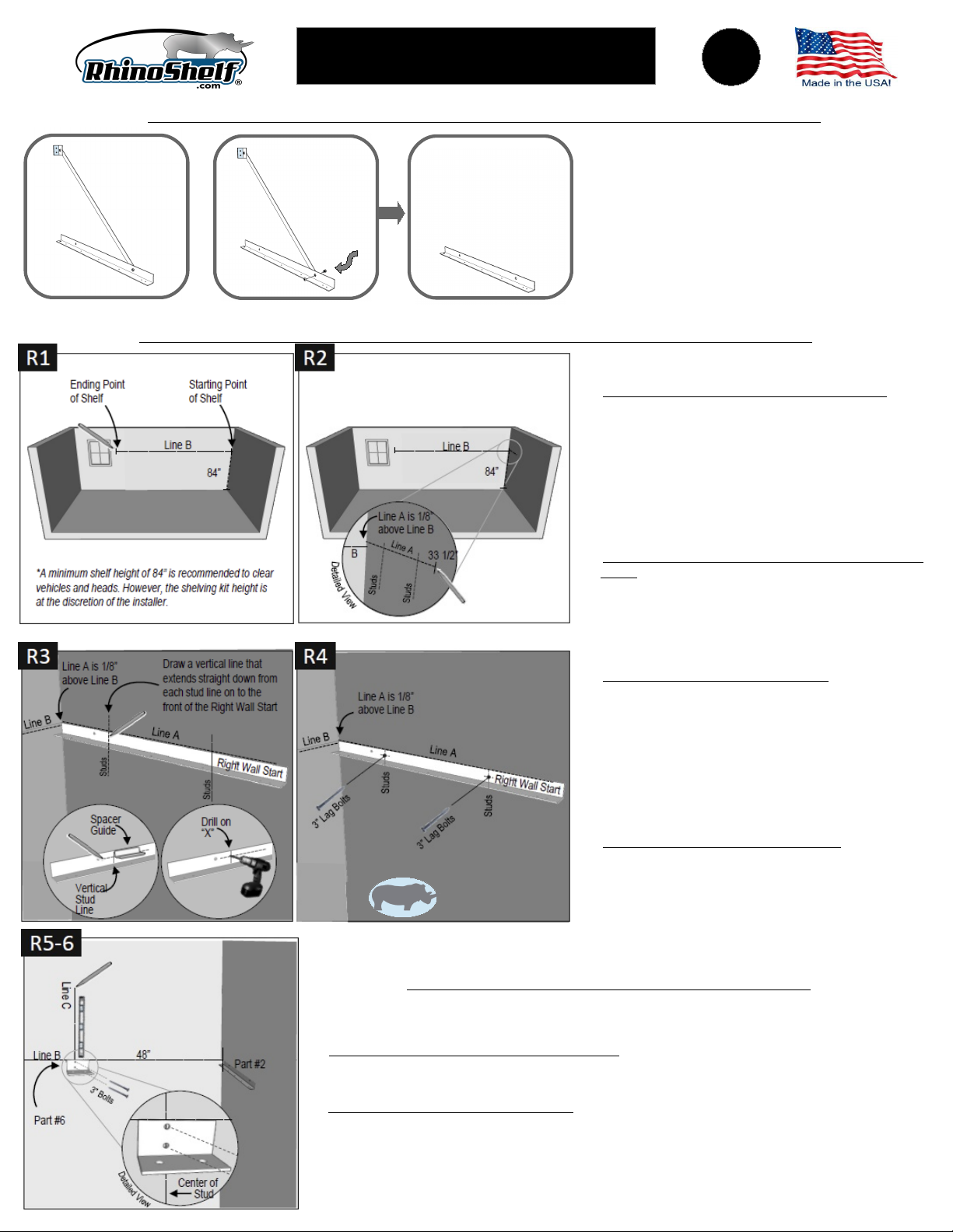
Left-End Assembly Remove nut & bolt from Left End
Assembly to get Left all Start
Left Wall Start
FIRST, DISASSEMBLE LEFT END ASSEMBLY TO
OBTAIN LEFT WALL START Remove the diagonal
support arm from the Left End Assembly by removing the
5/16" nut and bolt connecting the diagonal to the 33 1/2"
angled component This give you the Left Wall Start
component Set aside
DO THE SAME THING TO THE RIGHT END ASSEMBLY
TO OBTAIN RIGHT WALL START Save this piece for
later You will not be using the diagonals you have
removed
INSTALL LEFT WALL START
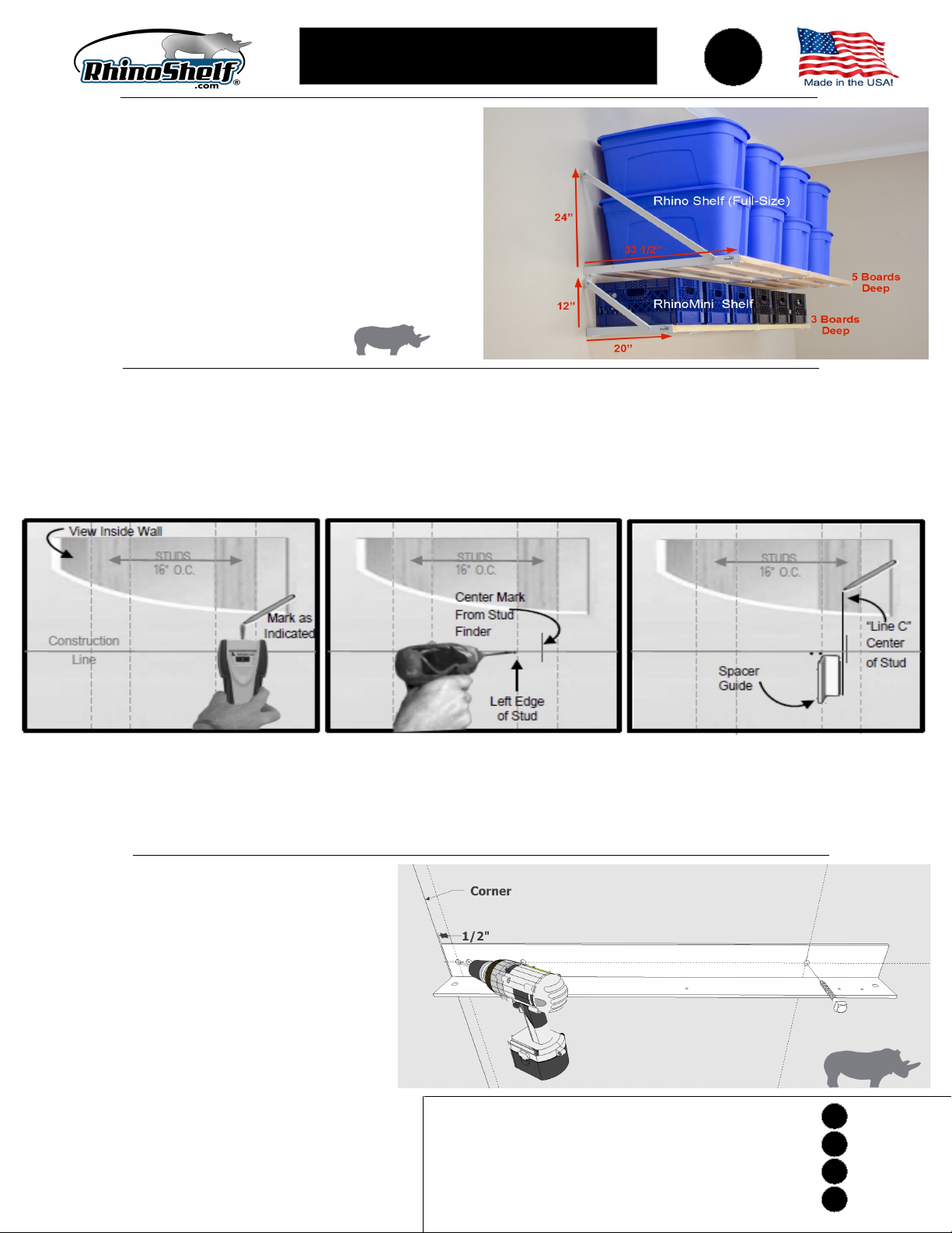
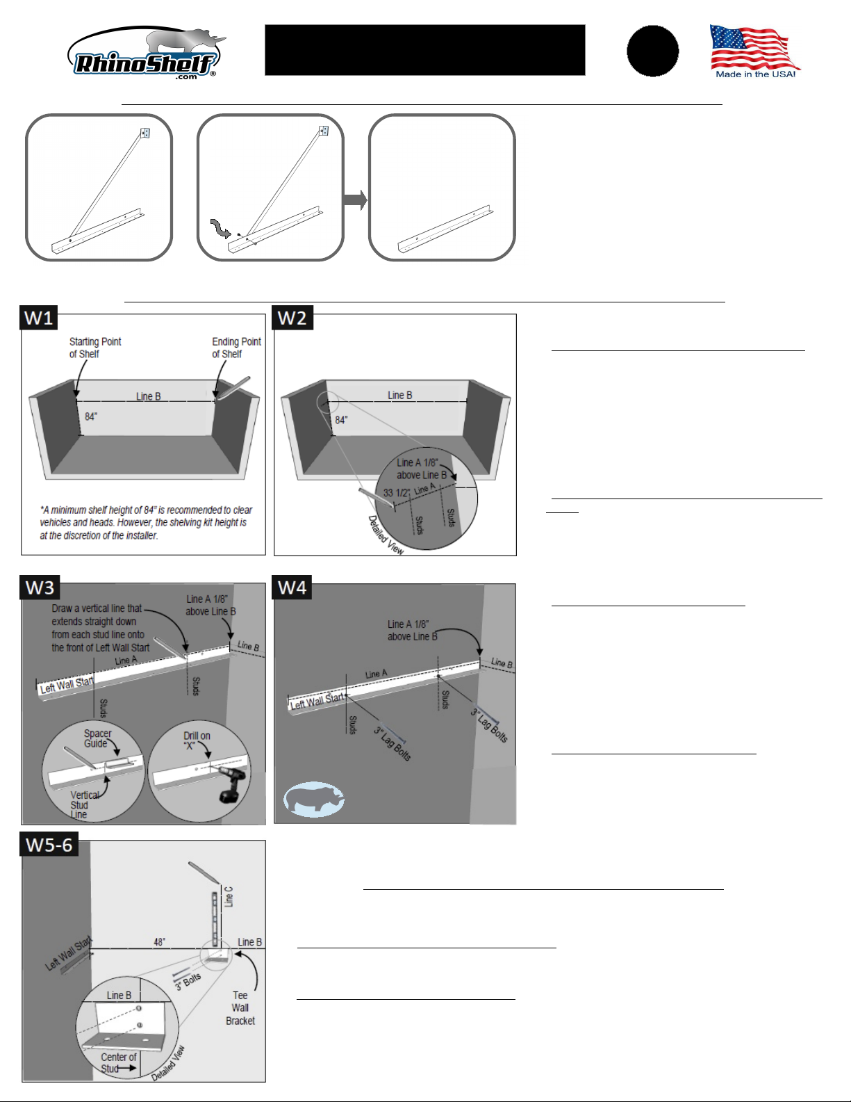
W1 MARK LOCATION OF SHELF ON FRONT WALL To
determine the starting point, in the left corner of the wall,
measure 84” from the floor and make a small mark This
will be your starting point From that point, draw a level
and horizontal line the length of the kit you ordered This
line will be referred to as Line B For example, if you
purchased a 12’ kit, from the starting point you would
draw a 12’ horizontal level line Locate the nearest stud
to the end of this line It may be to the left or right of this
point This stud will be your stopping point
W2 MARK LOCATION OF LEFT WALL START ON LEFT
WALL Starting from left corner, referencing Line B,
make a small horizontal mark on left wall 1/8” above
Line B From this mark, use a level to draw a 33 1/2”
horizontal line onto the left wall This is Line A Locate
and mark the center of each stud along Line A See
“How To Locate Center of Stud” on Page 2
W3 DRILL HOLES IN LEFT WALL START Align the top of
the Left Wall Start with Line A making sure the side with
only two holes is against the wall Place it 1/8” from
corner Holding the part in position, draw a vertical line
that extends straight down from each stud line onto the
front of the part Place the Left Wall Start on a scrap
piece of wood Use the 3/4” side of the Spacer Bar to
draw a perpendicular line across each vertical line on
the front of the part Drill holes through front of the Left
Wall Start on each “x” using a 1/4” drill bit
W4 FASTEN LEFT WALL START TO WALL Align the Left
Wall Start’s top edge with Line A, placing it 1/8” from
corner Make sure that the new 1/4” holes on the front
of the Left Wall Start are aligned with the center of stud
lines Holding the part in position, use a 3/16” bit to pre-
drill pilot hole through left 1/4” hole Use a 7/16” socket
wrench or nut driver to attach the Left Wall Start to the wall with 3” lag bolt Tighten until snug but movable
Ensure the part is level and that its top edge is aligned with Line A Drill second pilot hole through right
1/4” hole and attach second 3” lag bolt Level the part and tighten both 3" bolts
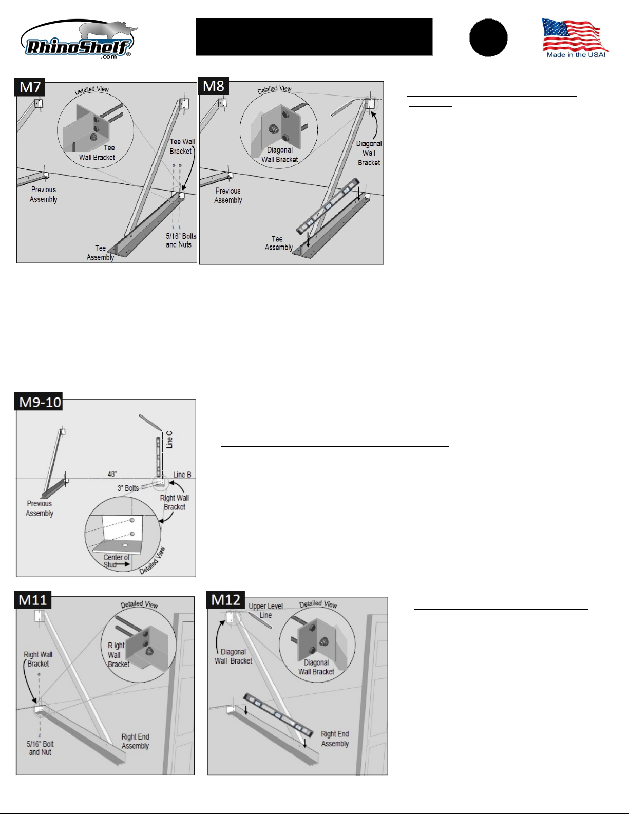
INSTALL TEE ASSEMBLY(IES) - IF YOUR KIT IS THE 4’ MODEL, SKIP TO STEP W9
W5 MARK LOCATION OF TEE ASSEMBLY ON WALL Along Line B find the first available stud nearest 48”
from the corner (or previously installed assembly) Locate the center of the stud and mark with a 2” vertical
mark (Line C)
W6 ATTACH TEE WALL BRACKET TO WALL Place bottom of 2’ level on Line B aligning with the edge of
Line C Make a 2” plumb (vertical) mark at top of the level Place the top of the Tee Wall Bracket on
horizontal Line B and align the center of the two holes on vertical Line C Holding the Tee Wall Bracket in
position, drill pilot hole in top hole using 3/16” drill bit Use a 7/16” socket wrench or nut driver to attach the
Tee Wall Bracket to wall with 3” lag bolt Tighten until snug but movable Ensure the Tee Wall Bracket is
level, drill second pilot hole and attach second 3” lag bolt Tighten both lag bolts
FOR RHINO MINI M3 AND M4 SEE “SPECIAL INSTRUCTIONS” BOTTOM OF PAGE 3
MINI Special Instruction
For Rhino Mini Pg 3