manuals.online logo
Brands
  1. Home
  2. •
  3. Brands
  4. •
  5. RHYTHM
  6. •
  7. Indoor Furnishing
  8. •
  9. RHYTHM H800-1-001 User manual

RHYTHM H800-1-001 User manual

Other RHYTHM Indoor Furnishing manuals

RHYTHM ComfortBase Flexstyle Series User manual

RHYTHM

RHYTHM ComfortBase Flexstyle Series User manual

RHYTHM Lifestyle Mobility Aids H800-1-002 User manual

RHYTHM

RHYTHM Lifestyle Mobility Aids H800-1-002 User manual

RHYTHM Multi LAL User manual

RHYTHM

RHYTHM Multi LAL User manual

Popular Indoor Furnishing manuals by other brands

Regency LWMS3015 Assembly instructions

Regency

Regency LWMS3015 Assembly instructions

Furniture of America CM7751C Assembly instructions

Furniture of America

Furniture of America CM7751C Assembly instructions

Safavieh Furniture Estella CNS5731 manual

Safavieh Furniture

Safavieh Furniture Estella CNS5731 manual

PLACES OF STYLE Ovalfuss Assembly instruction

PLACES OF STYLE

PLACES OF STYLE Ovalfuss Assembly instruction

Trasman 1138 Bo1 Assembly manual

Trasman

Trasman 1138 Bo1 Assembly manual

Costway JV10856 manual

Costway

Costway JV10856 manual

moss DESIGN Caisson Credenza Assembly instructions

moss DESIGN

moss DESIGN Caisson Credenza Assembly instructions

Aquaglide FULL DECK 15.0 owner's manual

Aquaglide

Aquaglide FULL DECK 15.0 owner's manual

AREBOS AR-HE-SW30 user manual

AREBOS

AREBOS AR-HE-SW30 user manual

Till-Hilft Fulda 87005.330 Assembly instructions

Till-Hilft

Till-Hilft Fulda 87005.330 Assembly instructions

Twoey Outside 2010 quick start guide

Twoey Outside

Twoey Outside 2010 quick start guide

Hettich Easys 200 operating instructions

Hettich

Hettich Easys 200 operating instructions

The bedboss RELAX 404 Series owner's manual

The bedboss

The bedboss RELAX 404 Series owner's manual

Oeseder Möbelindustrie Bern 991 720 Assembly instructions

Oeseder Möbelindustrie

Oeseder Möbelindustrie Bern 991 720 Assembly instructions

Costway HW68469 user manual

Costway

Costway HW68469 user manual

Next ALIX A27743 Assembly instructions

Next

Next ALIX A27743 Assembly instructions

BROSA Hans Assembly guide

BROSA

BROSA Hans Assembly guide

Prodigg MINIKA PBA015T-FUR installation manual

Prodigg

Prodigg MINIKA PBA015T-FUR installation manual

manuals.online logo
manuals.online logoBrands
  • About & Mission
  • Contact us
  • Privacy Policy
  • Terms and Conditions

Copyright 2025 Manuals.Online. All Rights Reserved.

Full Electric Bed Transfer Bench Shower Sprayer
SAFETY PRECAUTIONS
MAINTENANCE
WARRANTY
ADJUSTABLE
OVERBED TABLE
40 lb Weight Capacity
ITEM# H800-1-001
Limited Lifetime warranty is provided against any factory defects in material or workmanship of the frame.
One (1) year warranty against defective materials or workmanship on all other components, assemblies
and parts.
This warranty does not cover product failure due to misuse, negligence, improper storage or handling,
improper operation or unauthorized modifications. This warranty does not extend to non-durable
components which are subject to normal wear and tear and need periodic replacement.
For warranty service, it is recommended but not required that the product be returned to the Rhythm
Healthcare - LMA dealer through whom it was originally purchased. However, all Rhythm Healthcare - LMA
Dealers are qualified to assist you in obtaining warranty service. If the product is to be returned to Rhythm
Healthcare - LMA, prior authorization will be required. In the event of a defect covered by this warranty,
Rhythm Healthcare - LMA will determine if the product will be repaired or replaced.
Rhythm Healthcare - LMA products are identified by a serial or lot number label at the time of manufacture.
Removing or defacing the label may void this warranty. If you have questions about your Rhythm
Healthcare - LMA product or this warranty, please contact us at [email protected].
Clean, as necessary, with a soft cloth using a mild detergent and water. Rinse and dry thoroughly before
use. Do not use organic solvents, such as acetone or abrasive cleansers. Inspect weekly for wear and to
ensure all components are secure. If any component appears worn or is not working properly, contact your
dealer for repair and/or appropriate replacement parts.
Improper use of this product may result in personal injury and/or property damage. Rhythm Healthcare -
LMA is not liable for personal injury or property damage due to failure to follow the instructions or recom-
mendations in this manual or improper use of this product. If you discover a problem, contact your Rhythm
Healthcare - LMA Dealer for assistance.
This product is designed as a portable surface for reading, eating and keeping small personal items within
reach for INDOOR use only. The weight capacity is 40 lbs evenly distributed. Do not exceed this limit.
Do not lean on the suspended end of the table top as this may cause the table to tip.
Do not use as a walker or as an aid when sitting down or standing up.
Rhythm Healthcare, LLC
Lifestyle Mobility Aids
3200 Tyrone Blvd N
St. Petersburg, FL 33710
contactus@rhythmhc.com
Website: www.rhythmhc.com
(877) 843-6464
v1: 10/28/21
GENERAL EXPLANATION
PARTS
Table Top
Adjustable Height
Rear Locking Casters
2
If any components are damaged or missing, contact your authorized dealer immediately.
1. Table Top
2. Column Assembly (Release Rod not shown)
3. Adjustment Lever
- 20 x 2 " Bolt & Nut (1 each)
4
1/41/8
5. Mounting Bracket
6. Domed Phillips Head Bolts & Lock Washers (2 each)
6
7. Base
7
8. Casters, Locking (2 each)
8
9. Casters, Non-Locking (2 each)
11. Bolt Plate
11
13. Black Screw (DO NOT REMOVE until assembled)
14. Chrome Screw A (DO NOT REMOVE)
10. Bolt Sleeves (2 each)
- 15 x 2" Hex Bolts (2 each)
3/8
15. Chrome Screw B (To replace Black Screw after assembled)
5
12
ASSEMBLY INSTRUCTIONS
1
3
DO NOT REMOVE Chrome Screw A (14) marked “Do Not Remove”.
Apply light upward pressure anywhere on the table top and stop when the desired height is reached.
1
To Raise Table Top
Pull the Adjustment Lever upward and push down on the table top at the Column end.
end. When the Adjustment Lever is released, the Table Top will lock into place.
To Lower Table Top
The Casters on the Column end can be locked by stepping down on the tabs. To unlock, pull up on the tabs.
To Lock and Unlock Casters
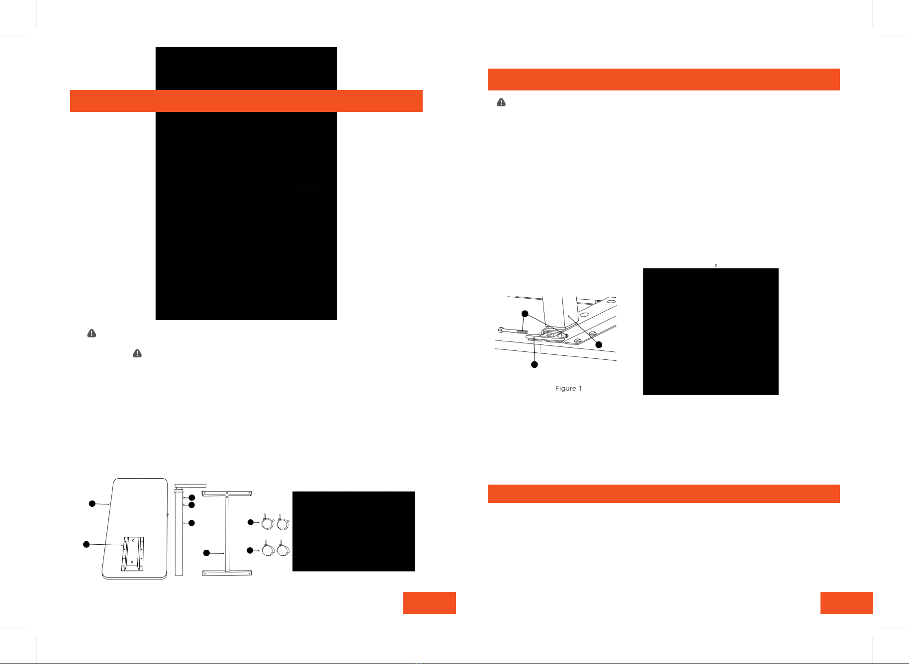
Figure 1 Figure 2
4. 12.
OPERATING INSTRUCTIONS
Do not put pressure on the opposite
Prior to assembly please read all instructions and save for future use. If you do not
understand any part of these instructions, contact a health care professional or authorized
dealer for assistance.
8. Turn the table upright placing the Casters on the floor. While pressing down on the Table
Top, remove the Black Screw in the Column Assembly (2) and replace it with Chrome Screw B
(15) included in the hardware package.
7. Insert the Locking Casters (8) into the Base near the Column Assembly (2) and insert the
Non-Locking Casters (9) intothe opposite end of the Base (7). Be sure to press the casters
in until they lock into place.
DO NOT remove the Black Screw from Column Assembly until Table is fully assembled.
This product utilizes a high tension, spring loaded mechanism and could raise
suddenly causing personal injury. DO NOT over tighten or use power tools to assemble.
1. Place the Table Top (1) on a level surface so the Mounting Bracket (5) faces up.
2. Check the Column Assembly (2) to ensure the Release Rod (not shown) is completely inside and not
protruding.
3. With the curved side toward table top, insert Adjustment Lever (3) into opening at top of Column
Assembly (2) making sure flat side of Adjustment Lever (3) rests on elease Rod. (Fig 1)
4. While holding Adjustment Lever, insert short end of Column Assembly (2) into Mounting Bracket (5) and
insert the two Domed Phillips Head Bolts and Lock Washers (6) but do not tighten. (Fig. 2)
5. Align holes of Adjustment Lever (3), Column Assembly (2) and Mounting Bracket (5) and secure with 1/4 -
20 x 2 1/8” Bolt and Nut (4). (Fig. 1) Then, tighten the two Domed Phillips Head Screws (6) at top of
Mounting Bracket (5).
6.Take Base (7) with caster holes facing away from Table Top and place end with mounting holes on Column
Assembly (2). Insert two large hex bolts (12) through Bolt Plate (11), through Bolt Sleeves (10), through
Column Assembly (2). Insert two large hex bolts (12) through Bolt Plate (11), through Bolt Sleeves (10),
through the Base (7) and into Column Assembly (2). Tighten with wrench. (Fig 2)