RIB PUSH-CA 30 User manual

1
2
1
1
2
3
4
2
A VASISTAS
TOP-HUNG OUTWARD OPENING
A PROJECTION
KIPPFENSTER
ABATIBLES
A SPORGERE
BOTTOM-HUNG
ABATTANTE
KLAPPFENSTER
PROYECTABLES
A
!
2
1
APPLICAZIONE A SPORGERE
TOP-HUNG OUTWARD OPENING APPLICATION
APPLICATION A PROJECTION
KLAPPFENSTER
APLICACIÓN EN CIERRES PROYECTABLES
APPLICAZIONE A VASISTAS
BOTTOM-HUNG APPLICATION
APLICATION ABATTANTE
KIPPFENSTER
APLICACIÓN EN CIERRES ABATIBLES
!
1
3
4
5
6
8
10
7
9
5
4
1
2
4
6
5
B
1
2
A

Campo d’applicazione
L’attuatore PUSH-CA 30 è destinato esclusivamente all’apertura e alla chiusura di finestre a
sporgere, a vasistas, a bilico e lucernari.
L’uso dell’attuatore per altre applicazioni deve essere autorizzato da RIB previa verifica tecnica
dell’applicazione.
1
Descrizione
Attuatore elettrico con catena a raccoglimento interno.
Idoneo per serramenti a vasistas e a sporgere con altezza a partire da cm 20.
Funzionamento a 230 Volt c.a.
Corse selezionabili.
PUSH-CA 30 è provvisto di finecorsa a microinterruttore e di una morsettiera estraibile
(fig. 4-B).
L’attuatore è corredato di accessori e dima di foratura per l’installazione al serramento e di relative
staffe per finestre a sporgere e a vasistas a richiesta (fig. 1-9, 1-4 e 1-2).
La catena di manovra è trattata contro l’ossidazione con riporto in Dacromet che la protegge
contro le applicazioni più severe.
Fornitura di serie
Ogni confezione del prodotto PUSH-CA 30 contiene (fig.1):
1. 1 Attuatore
2. 1 Supporto fissaggio attuatore
3. 1 Perno anteriore catena
4. 1 Staffa per finestre a sporgere
5. 6 Viti autofilettanti 4,8x13 UNI 6954
6. 1 Coppiglia
7. 1 Serracavo
8. 1 Spina di bloccaggio
9. 1 Dima di foratura
10. 1 Inserto regolazione corsa
1 Libretto di istruzioni
Controllare che tutti i componenti contenuti nella confezione siano integri.
2
Installazione
!L’installazione deve essere effettuata da personale tecnico specializzato.
!L’installazione deve essere effettuata con il serramento in posizione di chiusura.
!Scollegare l’alimentazione elettrica durante l’installazione.
!Controllare che le cerniere e la ferramenta utilizzata consentano all’attuatore di completare
la sua corsa. In caso contrario, la ferramenta potrebbe essere sottoposta a eccessive
sollecitazioni di trazione e/o di spinta da parte dell’attuatore e subire conseguenti danni
(vedi regolazione corsa).
a. Tracciare con la matita la linea di mezzeria del serramento, applicare la dima di foratura
autoadesiva (fig. 1-9) all’infisso ed eseguire i fori utilizzando il trapano e le punte di diametro
corrispondente a quanto indicato sulla dima stessa.
b. Rimuovere la dima autoadesiva e applicare la staffa (5-4 e 6-A) ed il supporto (fig. 5-2 e 6-2)
rispettivamente all’anta e al telaio utilizzando le viti in dotazione.
(NB. Le viti sono idonee per serramenti in alluminio.
Per il fissaggio su legno, utilizzare viti da legno Ø 4,8 di lunghezza adeguata allo spessore del
legno - fig. 1-5.)
c. L’attuatore (fig. 1-1) viene fornito con una corsa di 300 mm preregolata, che può essere
modificata come segue:
Regolazione della corsa tramite camma
Per modificare la corsa della catena dell’attuatore è necessario eseguire il collegamento elettrico
(vedi punto 3) oppure utilizzare il cavo di collaudo attuatore, quindi:
1. Alimentare l’attuatore.
2. Far uscire la catena di una lunghezza A corrispondente alla corsa desiderata come indicato
in Tabella A.
3. Aprire lo sportellino (vedere figura 2-1 e 3-1)
4. Inserire l’inserto di regolazione corsa (vedere figura 2-2 e 3-2). Esempio: con catena A=0
la corsa sarà di 90 mm.
5. Richiudere lo sportellino.
Nota: per l’applicazione a vasistas è consigliabile eseguire una regolazione della corsa
prima dell’installazione.
d. Montare l’attuatore sulla staffa.
Chiudere il serramento esercitando una pressione tale da garantire la tenuta delle guarnizioni.
Quindi avvitare il perno anteriore della catena e regolarne la posizione in corrispondenza della staffa.
e. Fissare l’attuatore con la coppiglia (fig. 1-6).
Assicurarsi che l’attuatore raggiunga correttamente le posizioni di intervento del fine corsa senza
ostacoli. (NB. L’attuatore viene fornito in posizione di finecorsa chiuso).
Dati tecnici
Consigli e norme di sicurezza:
- Si consiglia di far eseguire l’installazione dei prodotti RIB da personale specializzato nel settore e
che dia garanzie di adeguata competenza tecnica.
- Eseguire gli interventi come specificato dal costruttore.
- L’installatore deve verificare l’installazione e il corretto funzionamento dell’apparecchiatura.
- E’ vietato utilizzare il prodotto per scopi diversi da quelli previsti o impropri.
- Utilizzare ricambi originali.
- Utilizzare il comando a “uomo presente” nel caso in cui la finestra sia ad una altezza
inferiore a 2,5 m dal pavimento.
Avvertenze:
- Verificare che i componenti del serramento consentano la completa corsa di funzionamento
dell’attuatore. In caso contrario si possono creare danni agli elementi sollecitati e allo stesso
attuatore.
- Occorre aggiungere in prossimità dell’infisso una targhetta adesiva di “ATTENZIONE ORGANI
IN MOVIMENTO”.
- L’attuatore può provocare lesioni da schiacciamento o trascinamento!
Ha una forza di trazione e spinta di 300N/150N. I fissaggi e i punti di attacco degli accessori
devono essere adeguati per sopportare queste sollecitazioni.
- Il serramento deve essere provvisto di adeguati sistemi per il sostegno e la sicurezza dello
stesso, l’attuatore non può essere considerato parte di sostegno o sicurezza del serramento.
- Non toccare la catena quando è in movimento.
- Non entrare nel raggio d’azione della finestra durante il movimento.
- La finestra deve essere dotata di braccetti di sicurezza adeguati al peso dell’infisso.
- Scollegare l’alimentazione elettrica durante l’installazione e la manutenzione.
Collegamento elettrico
Attenzione: Pericolo di lesione e di morte per scarica elettrica.
Scollegare l’alimentazione agli attuatori prima di eseguire i collegamenti.
Avvertenza: Installare a monte della linea di comando dell’attuatore un interruttore generale
di alimentazione ominipolare con apertura minima dei contatti di 3 mm, con
intervento differenziale di 0,030 A.
Verificare l’esatta sezione dei cavi di alimentazione, che devono essere opportunamente
dimensionati in base all’assorbimento dell’attuatore.
Svitare le due viti indicate in figura 7-1.
Il collegamento elettrico deve avvenire come indicato nella figura 9.
Assicurarsi che l’impianto elettrico sia in conformità con le norme vigenti.
NB: Per la sicurezza dell’impianto si consiglia l’utilizzo di un pulsante senza ritenuta (uomo presente)
oppure l’alimentazione temporizzata per il tempo necessario alla manovra.
4
3
Manutenzione
Verificare annualmente il buono stato delle cerniere; la tenuta dell’attacco all’infisso e lo
stato generale del serramento.
Per un perfetto funzionamento si consiglia di lubrificare la catena con un grasso spray
al silicone.
Sostituire eventuali parti usurate.
Si consiglia di effettuare periodicamente un collaudo per constatare il buon funzionamento
dell’impianto con una frequenza non superiore ai 12 mesi; in impianti speciali è consigliato ogni
6 mesi.
Nb: Effettuare le manutenzioni tramite personale specializzato.
PUSH-CA 30
IT
FORZA DI SPINTA 150N
FORZA DI TRAZIONE 300N
CORSE REGOLABILI da 90 a 300 mm
VELOCITA’ DI TRASLAZIONE 40mm/sec.
REGOLAZIONE ANTERIORE Max 10 mm
COLLEGAMENTO IN
PARALLELO
SI
TENSIONE MONOFASE 230 V c.a.
CONSUMO 150 W
CORRENTE 0,8 A in c.a.
FREQUENZA 50 Hz
PROTEZIONE TERMICA 100°C
CONDENSATORE 4 µF
RELE’ INCORPORATO SI
MORSETTIERA ESTRAIBILE SI
GRADO DI PROTEZIONE IP 20

Field of application
The PUSH-CA 30 actuator is used exclusively for opening and closing bottom-hung, top-hung
outward-opening, up-and-over and skylight windows.
Use of the actuator for other applications must be authorised by RIB and is subject to technical
testing of the application.
1
Description
Electrical actuator with chain and internal magazine. Ideal for bottom-hung and top-hung
outward opening windows with height of at least 20 cm. 230 Volt ac functioning. Selectable
travel.
PUSH-CA 30 is fitted with a limit micro-switch, a removable terminal board (fig. 4-B).
It is also fitted with accessories and drilling template for fitting the actuator to the window
and special brackets for top-hung outward opening and bottom-hung windows (available on
request) (fig. 1-9, 1-4 and 1-2).
The chain has been treated with a Dacromet coating for protection against oxidation under the
most severe conditions.
Standard supply
Every PUSH-CA 30 package contains the following (fig. 1):
1. 1 Actuator
2. 1 Actuator fixing support
3. 1 Front pin for chain
4. 1 Bracket for top-hung outward opening windows
5. 6 4.8x13 UNI 6954 self-tapping screws
6. 1 Split pin
7. 1 Cable clamp
8. 1 Securing pin
9. 1 Drilling template
10. 1 Travel adjustment fitting
1 Instructions booklet
Check that all the components are present and undamaged.
2
Installation
!The actuator must be installed by specialised technical personnel.
!The actuator must be installed with the window closed.
!Disconnect the electrical power supply during installation.
!Check that the hinges and hardware used allow the actuator to open fully. If not, the
hardware may be damaged by the drive or thrust force of the actuator (see travel adjustment).
a. With a pencil, mark the midline of the window. Apply the self-adhesive drilling template (fig.
1-9) to the window and drill the holes using a drill and drill bits with a diameter corresponding
to the template.
b. Remove the self-adhesive drilling template and fit the bracket (5-4 and 6-A) and the support
(fig. 5-2 and 6-2) to the window and the frame respectively, using the screws supplied. (N.B.:
the screws are ideal for aluminium windows. For wood applications, use diameter 4.8 wood
screws with a length suitable for the thickness of the wood - fig. 1-5).
c. The actuator (fig. 1-1) is supplied with a travel of 300 mm and can be adjusted as follows:
Adjusting the travel using a cam
To modify the travel of the actuator chain, connect the actuator to the mains (see point 3)
or use the actuator test cable and then:
1. Power up the actuator.
2. Extract the chain by a length A equal to the travel required, as indicated in Table A.
3. Remove the cover (see fig. 2-1 and 3-1)
4. Fit the travel setting fitting (see fig. 2-2 and 3-2). Example: with chain A=0, the travel
is 90 mm.
5. Refit the cover.
Note: For bottom-hung applications, adjust the travel before fitting the actuator.
d. Fit the actuator to the bracket. Close the window, applying a light pressure to guarantee that
the gaskets are sealed. Then screw in the chain front pin and adjust the position at the bracket.
e. Secure the actuator with the split pin (fig. 1-6). Ensure that the actuator reaches the limit
switch positions correctly without being obstructed. (NB. The actuator is supplied with limit
switch in the closed position).
Technical data
Recommendations and safety standards:
- RIB products must be installed by specialised personnel with suitable technical skills.
- Perform the operations as specified by the manufacturer.
- The installer must check the installation and the correct functioning of the device.
- Do NOT use the product for purposes other than those specified.
- Use original spare parts.
- Use the deadman command if the window is less than 2.5 m from floor level.
Warnings:
- Check that the window components used allow the actuator to open fully. If not, the parts
subject to stress or the actuator itself may be damaged.
- Attach a “BEWARE MOVING PARTS” adhesive label near the frame.
- Crushing or trapping hazard! The actuator has a drive and thrust force of 300N/150N. The
hardware and the fittings for the accessories must be able to support these loads.
- The window must have suitable support and safety systems; the actuator cannot be considered
as a support or safety device for the window.
- Do NOT touch the chain when it is moving.
- Keep outside the range of the window’s movements when it is operating.
- The window must be fitted with safety arms which are suitable for the weight of the window.
- Disconnect the electrical power supply when installing, adjusting and repairing the actuator.
Electrical connection
Warning: injury or death - electrocution hazard.
Disconnect the power supply to the actuators before connecting the actuators or the system
Warning: There must always be a multi-polar mains switch with a minimum contact opening
of 3 mm and a differential of 0.030 A upstream of the actuator control line.
Check the cross-section of the power supply cable: it must have adequate dimensions for
the absorption of the actuator.
Unscrew the two screws indicated in fig. 7-1.
The electrical connections are indicated in fig. 9.
The electrical system must comply with current standards.
N.B.: To ensure the system is safe, use a spring return push-button (dead man) or a power supply
which is timed for the time required for movement.
4
3
Maintenance
Once a year, check that the hinges are in good condition, check that the actuator is firmly
secured to the window and check the general condition of the window.
For perfect functioning, lubricate the chain with silicon grease spray.
Change worn parts.
At least every 12 months, test the product to ensure the system is functioning correctly;
for special systems, this check should be done at least every 6 months.
N.B. Maintenance operations must be carried out by specialised personnel
PUSH-CA 30
GB
THRUST FORCE 150N
DRIVE FORCE 300N
ADJUSTABLE TRAVEL from 90 to 300 mm
OPERATING SPEED 40mm/sec.
FRONT ADJUSTMENT Max 10 mm
PARALLEL CONNECTION YES
SINGLE-PHASE POWER
SUPPLY
230 V ac
CONSUMPTION 150 W
CURRENT 0.8 A ac
FREQUENCY 50 Hz
THERMAL PROTECTION 100°C
CAPACITOR 4 µF
BUILT-IN RELAY YES
REMOVABLE TERMINAL
BOARD
YES
PROTECTION RATING IP 20

Champ d’application
L’actionneur PUSH-CA 30 est destiné exclusivement à l’ouverture et à la fermeture de fenêtres
à projection, abattantes, basculantes et fenêtres de toit. L’usage de l’actionneur pour d’autres
applications doit être préalablement autorisé par RIB après vérification technique.
1
Description
Actionneur électrique avec chaîne à enroulement interne. Pour fenêtres abattantes et à
projection ; hauteur des fenêtres : à partir de 20 cm. Fonctionnement à 230 Volts c.a.
Courses sélectionnables.
PUSH-CA 30 est équipé d’un fin de course à micro-rupteur et d’un bornier amovible
(fig. 4-B). L’actionneur est fourni avec accessoires, gabarit de perçage pour la pose sur
menuiseries et pattes de fixation soit pour fenêtres à projection, soit pour fenêtres abattantes sur
demande (fig. 1-9, 1-4, 1-2).
La chaîne de manœuvre est traitée contre l’oxydation avec report en Dacromet pour résister aux
milieux les plus hostiles.
Fourniture de série
Le kit du PUSH-CA 30 contient (fig.1) :
1. 1 Actionneur
2. 1 Support de fixation de l’actionneur
3. 1 Vis avant pour chaîne
4. 1 Flasque pour fenêtres à projection
5. 6 Vis autotarauds 4,8x13 UNI 6954
6. 1 Goupille
7. 1 Serre-câble
8. 1 Cheville de serrage
9. 1 Gabarit de perçage
10. 1 Régulateur de course
1 Notice d’instructions
Contrôlez si tous les composants contenus dans le kit sont en bon état.
2
Installation
!L’installation doit être effectuée par des techniciens spécialisés.
!L’installation doit être effectuée avec la fenêtre fermée.
!Avant de commencer l’installation, coupez l’alimentation électrique.
!Vérifiez si les charnières ou les ferrures utilisées permettent à l’actionneur d’ouvrir
complètement la fenêtre. Si ce n’est pas le cas, les ferrures pourraient s’abîmer, sollicitées
par la force de traction et/ou de poussée de l’actionneur (voir Réglage de la course).
a. Tracez la ligne médiane de la fenêtre au crayon, appliquez le gabarit de perçage autocollant (fig.
1-9) sur le châssis et percez les trous en utilisant une perceuse et des forets correspondant
aux indications du gabarit.
b. Otez le gabarit autocollant ; appliquez et vissez la flasque (fig. 5-4 et 6-A) sur l’ouvrant et le
support (fig. 5-2 et 6-2) sur le dormant avec les vis fournies dans le kit. (NB : Ces vis sont
pour menuiseries en alu. Pour le montage sur bois, utilisez des vis à bois, Ø 4,8 et longueur
proportionnelle à l’épaisseur du bois fig. 1-5).
c. L’actionneur (fig. 1-1) est réglé en usine sur une course de 300 mm. Pour modifier la course,
procédez comme suit:
Réglage de la course par came
Pour modifier la course de la chaîne de l’actionneur, vous pouvez soit effectuer la connexion
électrique (voir point 3), soit utiliser le câble d’essai de l’actionneur ; après quoi :
1. Alimentez l’actionneur.
2. Faites sortir une longueur de chaîne A correspondant à la course souhaitée comme l’indique
la table A.
3. Otez la plaquette (voir figures 2-1 et 3-1)
4. Introduisez le régulateur de course (voir figures 2-2 et 3-2). Exemple : avec longueur de
chaîne A=0, la course sera de 90 mm.
5. Remontez la plaquette.
Note : pour l’installation sur fenêtre abattante, il est conseillé d’effectuer le réglage de
la course avant l’installation.
d. Montez l’actionneur sur la flasque. Fermez la fenêtre en exerçant une pression pour que la
fermeture soit bien hermétique. Vissez ensuite la vis avant de la chaîne et réglez la position
à hauteur de la flasque.
e. Fixez l’actionneur avec la goupille (fig. 1-6). Vérifiez si l’actionneur atteint correctement les
positions qui provoquent l’intervention des fins de course sans rencontrer d’obstacles. (NB :
L’actionneur sort d’usine en position de fin de course fermé).
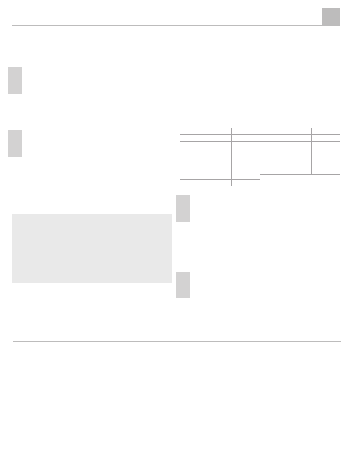
Caractéristiques techniques
Conseils et normes de sécurité
- Nous vous conseillons de confier l’installation des produits RIB au personnel spécialisé dans
ce secteur, vous offrant toutes les garanties de compétence technique.
- Effectuez les interventions en respectant les instructions du fabricant.
- L’installateur doit vérifier l’installation et le fonctionnement de l’actionneur.
- Tout usage du produit non prévu ou inopiné est interdit.
- Utilisez des pièces détachées d’origine.
- Utilisez la commande “homme présent” si la fenêtre est installée à moins de 2,5 m du
sol.
Mises en garde
- Vérifiez si les composants de la fenêtre permettent la course complète de l’actionneur. Si ce
n’est pas le cas, les éléments sollicités et l’actionneur peuvent s’abîmer.
- Il faut coller près de l’huisserie une plaquette adhésive indiquant «ATTENTION ORGANES EN
MOUVEMENT».
- L’actionneur présente un danger d’écrasement ou d’entraînement ! Sa force de traction et de
poussée est de 300N/150N. Les fixations et les points d’assemblage des accessoires doivent
être en mesure de supporter ces sollicitations.
- La menuiserie doit être équipée de systèmes en mesure de supporter l’actionneur et garantir
le fonctionnement en toute sécurité ; l’actionneur ne peut être considéré comme une pièce de
support ou de sécurité de la fenêtre.
- Ne touchez pas la chaîne quand elle est en mouvement.
- N’entrez pas dans le rayon d’action de la fenêtre pendant le mouvement.
- La fenêtre doit être équipée de compas-freins de sécurité adaptés au poids de la menuiserie.
- Coupez l’alimentation électrique avant de commencer l’installation et la maintenance.
Raccordement électrique
Attention : Danger d’électrocution. Coupez l’alimentation des actionneurs avant de travailler
sur le circuit électrique.
Mise en garde : Installez en amont de la ligne de commande de l’actionneur un interrupteur
général d’alimentation omnipolaire dont les contacts ont une ouverture
minimum de 3 mm, avec intervention différentielle de 0,030 A.
Vérifiez si la section des câbles d’alimentation est exacte, leur dimensionnement étant fonction de
l’absorption de l’actionneur.
Dévissez les deux vis comme l’indique la figure 7-1.
Effectuez le raccordement électrique comme l’indique la figure 9.
Assurez-vous que le circuit électrique est conforme aux normes en vigueur.
NB : Il est conseillé, pour la sécurité du circuit, d’installer un bouton-poussoir (homme présent) ou
bien une alimentation temporisée sur la durée de la manœuvre.
4
3
Maintenance
Vérifiez une fois par an l’état des charnières, la solidité des fixations de l’actionneur et
l’état général de la menuiserie.
Pour un parfait fonctionnement, il est conseillé de lubrifier la chaîne avec de la graisse
au silicone en spray.
Si nécessaire, remplacez les pièces usées.
Nous vous conseillons d’effectuer périodiquement un essai pour contrôler le fonctionnement de
l’installation au moins une fois par an ; cet essai doit avoir lieu une fois tous les 6 mois si votre
installation est personnalisée.
NB : Confiez la maintenance à un technicien spécialisé.
PUSH-CA 30
F
FORCE DE POUSSEE 150N
FORCE DE TRACTION 300N
COURSES REGLABLES de 90 à 300 mm
VITESSE DE TRANSLATION 40mm/s
REGLAGE AVANT Max 10 mm
RACCORDEMENT EN
PARALLELE
OUI
TENSION MONOPHASEE 230V c.a.
CONSOMMATION 150w
COURANT 0,8A in c.a.
FREQUENCE 50 Hz
PROTECTION THERMIQUE 100°C
CONDENSATEUR 4 µF
RELAIS INCORPORE OUI
BORNIER AMOVIBLE OUI
DEGRE DE PROTECTION IP 20

Anwendungsbereich
Der Antrieb PUSH-CA 30 ist ausschließlich zum Öffnen und zum Schließen von Kipp-, Klapp- und
Schwingfenstern sowie Dachoberlichtern bestimmt. Ein davon abweichender Einsatz ist von RIB
nach vorheriger technischer Prüfung der Anwendung zu genehmigen.
1
Beschreibung
Es handelt sich um einen elektrischen Kettenantrieb, bei dem die Kette in einem Gehäuse
aufgerollt wird. Er eignet sich für Kipp- und Klappfenster ab einer Höhe von 20 cm.
Der Betrieb des Systems erfolgt bei einer Spannung von 230 Volt Ws. Die Hübe können
eingestellt werden.
Das Modell PUSH-CA 30 ist mit einem Mikroendschalter, mit einer abziehbaren Klemmleiste (Abb.
4-B) ausgestattet. Zur Ausstattung gehören ferner Bohrschablonen zur Montage an das Fenster
und die entsprechenden Bügel für Kipp- und Klappfenster auf Anfrage (Abb. 1-9, 1-4 und 1-2).
Die Antriebskette ist mit Dacromet behandelt, das sie auch bei schwierigsten Einsatzbedingungen
mit einem zuverlässigen Rostschutz ausstattet.
Serienmäßige Lieferung
Jede PUSH-CA 30-Packung enthält (Abb. 1):
1. 1 Antrieb
2. 1 Halterung zur Befestigung des Antriebs
3. 1 vorderer Kettenstift
4. 1 Bügel für Klappfenster
5. 6 selbstschneidende Schrauben 4,8x13 UNI 6954
6. 1 Splint
7. 1 Kabelschelle
8. 1 Sicherungsstift
9. 1 Bohrschablone
10. 1 Einsatz zur Einstellung des Hubs
1 Handbuch
Prüfen, ob sich der Packungsinhalt in einwandfreiem Zustand befindet.
2
Installation
!Die Installation muß von technischem Fachpersonal ausgeführt werden.
!Die Montage muß bei geschlossenem Fenster erfolgen.
!Die Spannungsversorgung muß während der Installation getrennt sein.
!Sicherstellen, daß die verwendeten Lager bzw. Beschläge den gesamten Öffnungshub
des Antriebs zulassen.
Andernfalls könnten die Beschläge durch die Druck- bzw. Zugkraft des Antriebs beschädigt
werden (siehe Hubeinstellung).
a. Die Mittellinie des Fensters anzeichnen. Die selbstklebenden Bohrschablon am Fenster
anbringen (Abb. 1-9) und die Bohrungen mit entsprechendem Bohreinsatz gemäß Vorgabe
vornehmen.
b. Die selbstklebenden Bohrschablone entfernen und den Bügel (Abb. 5-4 und 6-A) sowie die
Halterung (Abb. 5-2 und 6-2) mit den mitgelieferten Schrauben jeweils an Fensterflügel und
-rahmen befestigen. (HINWEIS: Die Schrauben eigenen sich für Aluminiumfenster. Bei der
Befestigung an Holzfenstern müssen Holzschrauben Ø 4,8 passender Länge, je nach Holzdicke,
verwendet werden - Abb. 1-5).
c. Der Antriebshub (Abb. 1-1) wird werkseitig auf 300 mm eingestellt und kann wie folgt verändert
werden:
Hubeinstellung am Nocken
Zur Änderung des Kettenhubs des Antriebs muß der elektrische Anschluß vorgenommen (siehe
Punkt 3), oder das Prüfkabel des Antriebs verwendet werden. Danach wie folgt vorgehen:
1. Den Antrieb mit Spannung versorgen.
2. Die Kette um eine Länge A herausziehen, die dem gewünschten Hub entspricht; siehe
Tabelle A.
3. Die Abdeckung öffnen (siehe Abbildung 2-1 und 3-1)
4. Den Einsatz zur Hubeinstellung (siehe Abbildung 2-2 und 3-2) einsetzen. Beispiel: Bei Kette
A=0 beträgt der Hub 90 mm.
5. Die Abdeckung wieder schließen
Hinweis: Bei der Anwendung an Kippfenstern muß die Einstellung des Hubs vor der
Installation erfolgen.
d. Den Antrieb auf den Bügel montieren. Das Fenster schließen und dabei so stark andrücken,
daß die Abdichtung durch die Dichtungen gewährleistet ist. Danach den vorderen Kettenstift
festschrauben und die Position in Übereinstimmung mit dem Bügel einstellen.
e. Den Antrieb mit dem Splint (Abb. 1-6) befestigen. Sicherstellen, daß der Antrieb die
Ansprechstellungen des Endschalters ohne Hindernisse erreicht. (Hinweis: Der Antrieb wird
mit Endschalter in geschlossener Stellung geschlossen geliefert).
Technische Daten
Empfehlungen und Sicherheitsvorschriften:
- Es wird empfohlen, die RIB-Produkte von Fachpersonal installieren zu lassen, das in der Lage
ist, eine angemessene technische Kompetenz zu gewährleisten.
- Alle Eingriffe sind gemäß Herstellerhinweisen auszuführen.
- Der Installateur muß die Installation und die korrekte Funktion der Anlage prüfen.
- Der unsachgemäße Gebrauch bzw. ein nicht vom Hersteller vorgesehener Gebrauch der Anlage
ist verboten.
- Originalersatzteile verwenden.
- Die “Totmannschaltung” verwenden, falls das Fenster auf einer Höhe von weniger als
2,5 m vom Boden angeordnet ist.
Hinweise:
- Sicherstellen, daß die Lager und Beschläge des Fensters den kompletten Öffnungshub des
Antriebs zulassen. Andernfalls könnten Schäden an den genannten Teilen oder am Antrieb
entstehen.
- Neben dem Fenster muß ein Klebeschild mit der Aufschrift “ACHTUNG, TEILE IN BEWEGUNG”
angebracht werden.
- Es besteht Quetsch bzw. Einzugsgefahr! Der Antrieb hat eine Zug- und Druckkraft von
300N/150N. Die Befestigungen und Befestigungsstellen des Zubehörs müssen diesen Kräften
standhalten.
- Das Fenster muß mit angemessenen Stützen und Sicherheitssystemen ausgestattet sein. Der
Antrieb kann nicht als dergleichen betrachtet werden.
- Die Kette nicht berühren, wenn sie in Bewegung ist.
- Das sich in Bewegung befindliche Fenster weder berühren, noch in dessen Bewegungsradius
greifen.
- Achtung: Das Fenster muß mit auf das Gewicht abgestimmten Sicherheitsarmen ausgestattet
sein.
- Während der Installation und der Wartung muß die Spannungsversorgung getrennt werden.
Elektroanschluß
Achtung: Es besteht Verletzungs- und Lebensgefahr durch Stromschlag. Vor dem Anschluß
ist die Spannungsversorgung zu unterbrechen.
Warnung: Dem Steuerkreis des Antriebs ist stets ein allpoliger Hauptschalter mit einer
Mindestkontaktöffnung von 3 mm mit einem Schaltvermögen von 0,030 A
vorzuschalten.
Den exakten Querschnitt der Versorgungskabel ermitteln, da für diese Kabel, auf der
Grundlage der Stromaufnahme des Antriebs, der richtige Querschnitt gewählt werden muß.
Die beiden Schrauben aus Abbildung 7-1 lösen.
Den Stromanschluß gemäß Abbildung 9 vornehmen.
Sicherstellen, daß die elektrischen Anschlüsse den einschlägigen Vorschriften entsprechen.
HINWEIS: Zur Sicherheit der Anlage wird empfohlen, einen nicht rastenden Taster zu verwenden
(Totmannschaltung), oder die Versorgung, gemäß der für die Betätigung nötigen Zeit,
zu takten.
4
3
Wartung
Einmal jährlich den Zustand der Lager, die Befestigung am Fenster und den allgemeinen
Zustand des Fensters prüfen.
Zur Gewährleistung eines einwandfreien Betriebs wird ferner empfohlen die Kette mit
Silikonspray einzufetten.
Eventuell verschlissene Teile austauschen.
Ferner sollte die Anlage in regelmäßigen Abständen (mindestens einmal jährlich; bei Spezialanlagen
mindestens einmal halbjährlich) überprüft werden.
Hinweis: Die Wartung von Fachpersonal ausführen lassen.
PUSH-CA 30
D
DRUCKKRAFT 150N
ZUGKRAFT 300N
HUB EINSTELLBAR von 90 bis 300 mm
LAUFGESCHWINDIGKEIT 40mm/s
FEINEINSTELLUNG VORNE max. 10 mm
PARALLELSCHALTUNG JA
EINPHASEN-SPANNUNG 230V Ws
STROMVERBRAUCH 150W
STROMSTÄRKE 0,8A Ws
FREQUENZ 50 Hz
WÄRMESCHUTZ 100°C
KONDENSATOR 4 µF
EINGEBAUTES RELAIS JA
ABZIEHBARE
KLEMMLEISTE
JA
SCHUTZART IP 20
Table of contents
Languages:
Other RIB Indoor Furnishing manuals
Popular Indoor Furnishing manuals by other brands

Regency
Regency LWMS3015 Assembly instructions

Furniture of America
Furniture of America CM7751C Assembly instructions

Safavieh Furniture
Safavieh Furniture Estella CNS5731 manual

PLACES OF STYLE
PLACES OF STYLE Ovalfuss Assembly instruction

Trasman
Trasman 1138 Bo1 Assembly manual

Costway
Costway JV10856 manual